11 Steps to Make Ductwork: Duct Manufacturing Process
Have you ever wondered how the air ducts in your home or office are made? In this fascinating blog post, we'll take you on a journey through the intriguing process…
Ever wondered how air ducts are made with precision and efficiency? The TDF flange forming machine is your answer. This article will guide you through its operation, highlighting the machine’s capabilities, including producing flanges for air ducts, essential for HVAC systems. Learn how to set up, operate, and maintain this powerful tool, ensuring top-notch performance and safety in your projects. Discover the technical details and practical tips to maximize your machine’s potential.
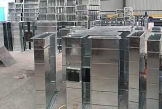
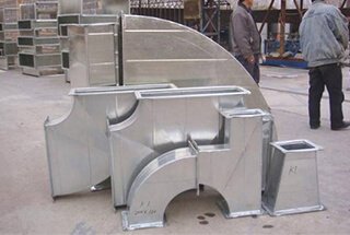
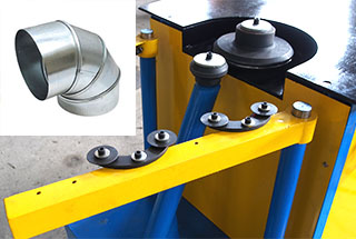
The TDF flange forming machine is primarily used for producing square and rectangular air ducts and TDF self-made semi-finished flanges. It can also be used to create finished ducts by combining it with a duct production line, shearing machine, folding machine, locking machine, and corner code machine.
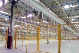
Our company offers two types of TDF flange forming machines: T12 and T15. The formed iron plate thickness ranges from 0.5mm to 1.5mm. These machines are ideal for on-site manufacturing of ventilation exhaust ducts in industries such as mining, hotels, shopping malls, and construction, due to their compact size, lightweight design, ease of movement, adjustability, ease of operation, and reliability.
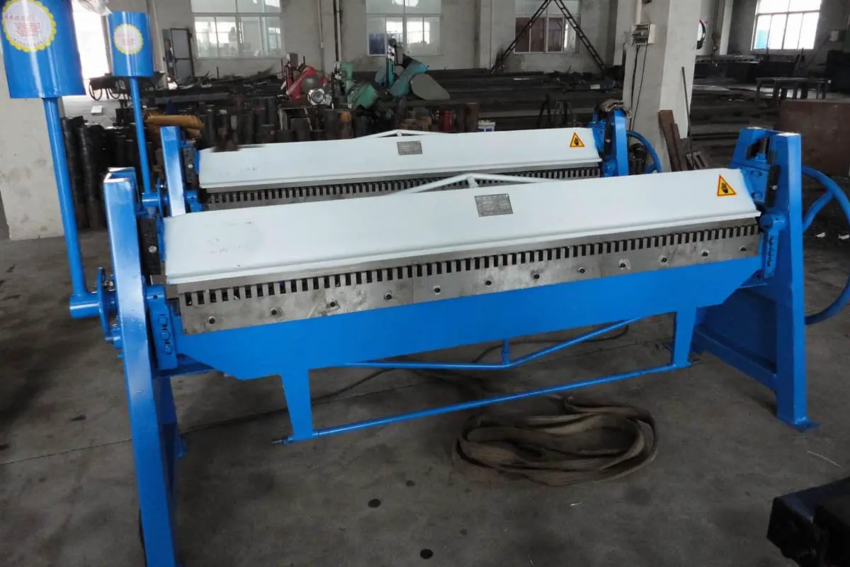
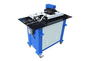
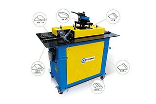
The following are use case diagrams.
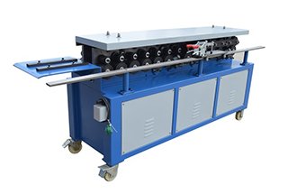
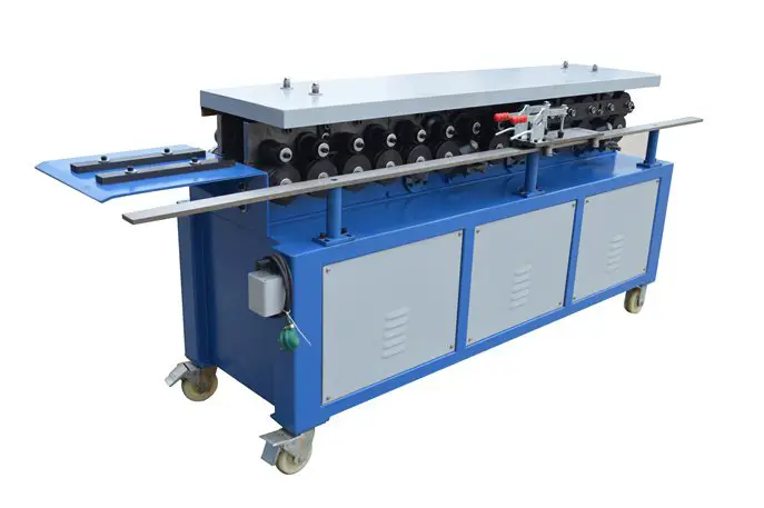
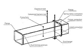
Here are the drawings:
TDF Flange Forming Machine Components: The machine consists of a rack, a transmission component, a flange forming component, a hook forming component, and a power component (motor and reducer).
Overall Dimensions: The machine measures 2700mm in length, 700mm in width, and 1100mm in height.
Weight: The machine weighs approximately 850 kilograms.
Reducer Model: The machine uses an RV110 reducer with a gear ratio of 25-30.
Motor Power: The motor has a power output of 3 kW.
Applicable Material: The machine is designed to work with galvanized ordinary plates with a thickness of 0.6mm to 1.2mm.
Working Speed: On average, the machine operates at a speed of about 14 meters per minute.
Length Limitation: There is no limit to the length of material that can be processed by the machine.
Product Accuracy: The size error does not exceed ±0.6mm, and the angle error does not exceed ±2 degrees.
Model and Technical Parameters
Table 1:
| Model | Motor (KW) | Plate Thickness (mm) | Shape | “a”size (mm) | Weight (kg) | Dimension (L.W.H) |
| T-12 | 3 | 0.5-1.2 |  | 35±0.5 | 850 | 2700×700×1100 |
Table 2
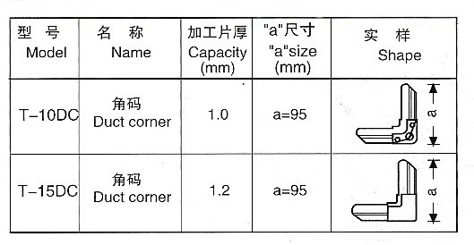
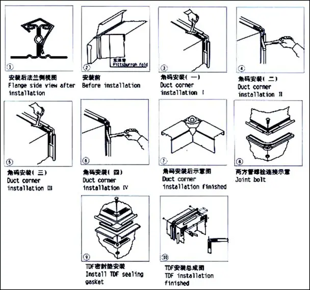
The duct corner is processed using a pair of corner molds, one set for cutting and the other for press forming. The process is performed using a 40T punch, although a 25T punch can also be used for processing T-10 DC type duct corners.
Regarding the hook code cutting size, the width is 60mm and the thickness is 1.0mm lath. The machine is equipped with a reel shearing machine, eliminating the need for separate cutting.
The maximum altitude shall not exceed 2000 meters.
The surrounding temperature should range between -10°C to +40°C.
When the temperature is +40°C, the air relative humidity should not exceed 50%. When the temperature is +25°C, the air relative humidity should not exceed 90%.
The atmospheric conditions should be free of dangerous substances that could cause explosions, and should not contain gases or conductive dusts that could corrode metal or damage insulating gases.
The power requirements are as follows: the voltage should be within 342-418V, and the three-phase power unbalance voltage should be controlled to a range where both negative and zero sequences do not exceed 2% of the sequence. The frequency should be within 49.5-50.5.
The T12 TDF forming machine is comprised of a workbench, a transmission section, and a forming section. The outline dimensions can be seen in the attached figure (Fig. 1).
TDF flange forming machine rack and workbench
The rack is a welded shell made of 8# national standard channel, which is sturdy and reliable. The entire transmission section, forming section, and reducer are installed on the shell. The end of the side plate is fixed to the table panel with a horizontal adjusting channel positioning plate on the panel.
Transmission Part
The entire transmission system consists of a turbine box that is driven by a turbine reducer with a transmission ratio of 30:1 (or other ratios), powered by a 3 kW national standard motor. The reducer drives two drive shafts through sprockets and a chain, and the drive shaft gears drive the transit shaft. The movement of the whole system is then driven by multiple transit gear wheels.
Both sides of the forming components are made up of 14 rollers, with one side forming flanges and the other side forming hooks. The forming rollers are constructed of GCr15 bearing steel that has undergone salt bath heat treatment and finishing, making them durable.
The shafts and gears are heat-treated to ensure their performance and longevity. Each tail has an adjustable device to ensure that the flange aligns with the required specifications.
The side plate is fabricated from forged steel and has undergone finishing. The TDF flange forming machine has 14 groups of forming shafts, each of which is equipped with a drive gear and left and right rollers. The left side consists of the hook roller group, while the right side contains the flange roller group. Additionally, the right side flange forming component features a rubber material-holding wheel and a feeding car to ensure stability during the forming process and produce qualified products.
Matters Need Attention
Ensure that no components are lost or omitted during transportation. Carefully inspect all relevant parts to confirm that they are complete and undamaged before installation.
Before lifting the machine, thoroughly check the lifting device to ensure it meets the requirements. Use at least two slings of equal length during the lifting process. Keep the lifting hook point at the center position and maintain a good center of gravity to avoid the machine losing its balance and flipping. When unloading, place the machine slowly on a flat ground, with the four feet touching the ground first and no one hanging in the air. Use bearers if necessary. The machine should not be tilted or placed at an angle, as this can cause deformation and affect its function.
The machine should be installed on a level, hardened ground.
Assemble a suitable power source (with the appropriate voltage, phase, and frequency, etc.) and an earthing wire according to the requirements. Install the electrical system according to the standard color code.
Lubricating according to the following requirement:
| No. | Lubrication Parts | Lubricating Oil | Lubrication Time |
| 1 | Gear and drive chain | Grease | Every working 40 hours |
| 2 | Ball bearing and a plane bearing | Grease | Every working 40 hours |
| 3 | Drive chain wheel | Light lubricating oil | Every working 80 hours |
| 4 | Transmission chain wheel | Light lubricating oil | Apply the lubricant to drive chain |
| 5 | Speed reducer | Gear oil | Replace oil once every three months |
Check before starting the machine
Fill the machine with lubricating grease or oil as required.
Thoroughly inspect each part, including the tensioning chain, drive belt tension, leakage protection, and fastening bolts, to ensure that all parts are in good condition.
Idle working for several minutes for inspecting the machine running conditions
The use of an auxiliary feeding trolley depends on the width of the plate and flange.
When the plate length is less than 180mm, the use of a feeding trolley is necessary. The plate is placed on the trolley, secured with two clamps, and pushed forward by workers during the rolling process.
If the plate length is greater than 180mm, the trolley can be dismantled from the side and stored in a suitable location.
During the first use, measure and evaluate the results. If there is unequal clearance on both sides, adjust the stopping plate position and the parallelism between the material guide plate and feeding direction.
If the large right-angle edge of the flange exceeds 90°, lower the holding rubber wheel to increase the holding force. If the flange is curving upward or downward, adjust the shape-adjusting wheel accordingly.
Note that this machine is designed for forming through folding and should not be used as a casting rolling mill.
Therefore, a certain gap (approx. plate thickness plus 0.1-0.2mm) between upper, middle and lower rollers is necessary, the gap has been adjusted before leaving factory, users shall not arbitrarily turn the countersunk head screws ③fastening bolt ④ and disc spring ![]() ( see figure 2 and 5 )
( see figure 2 and 5 )
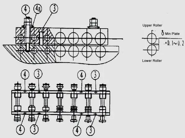
Fig.5
If the gap between the rollers varies due to loosened bolt nuts ③ and screws ④ or other reasons, adjust as follows:
Loosen all nuts ④ and place a plate with the same thickness as the gap between the rollers. Adjust screw ③ until the gaps between the four-side rollers are nearly equal. Then tighten nut ④ [δ=Min. plate thickness + 0.1-0.2]. If you want the minimum plate gap, it is acceptable to leave a slight space.
Bone-shape adjustment
To accommodate sheets of varying widths or thicknesses, loosen the screws on the leading-in positioning plate and move the plate in a direction parallel to the slot. Then, tighten the guiding plate.
If during the production of flanges, the sheets are thin and the size of the flange side hook is insufficient, adjust the flange side feeding plate slightly towards the inside.
The TDF flange forming machine must be operated by a professional operator who is thoroughly familiar with the machine’s structure and performance and has received proper training. The operator must follow the safety operation procedures strictly. If multiple operators are involved, a professional person must be in charge of directing production.
Regularly inspect the TDF flange forming machine, including its condition, earthing resistance, and leakage protection, to ensure that all circuits and electrical components are in safe working condition.
Before performing maintenance or inspection, the power must be cut off and the key removed and locked.
The power voltage should not exceed the rated voltage by more than 10% to prevent electrical insulation degradation.
No repairs or adjustments should be made while the machine is in operation.
It is forbidden to touch the rotating rollers, chains, and gears with your hands.
If any abnormal sounds or odors occur, immediately stop the machine and troubleshoot the problem.
The machine’s protective cover must be intact. An incompletely assembled machine cannot be put into production.
Before performing maintenance on the machine, the maintenance personnel must be familiar with its performance, specifications, safety measures, mechanism positions and functions, mechanical, electrical, and transmission theories, as well as the relationship between order and action sequence and operating procedures.
Lubricating grease or oil should be added before each shift in accordance with the lubrication requirements.
It is prohibited to form sheets with welding scars, burrs, or sheets that are too thick.
Considerations for shock, moisture, and dust protection should be taken for the motor, electrical, and control components. During the rainy season, if the machine has not been used for a long period of time (more than one month), the motor and electrical insulation should be reviewed and dehumidified before use.
Ensure that any exposed hoses and wires are intact.
Keep the roller surface clean and remove impurities and iron scraps in a timely manner to prolong the machine’s service life.
Establish an equipment file and create a regular maintenance plan, including maintenance records and logs.
At the end of each shift, clean up all scraps, remove iron and dust, and turn off the power and lock the machine.
Matters need attention
The TDF flange forming machine has an input voltage of 380V, and the input power socket must have a proper grounding line to ensure safety.
The shared ball bearings on the TDF flange forming machine have been fully lubricated and generally do not require special care. However, when using the machine for the first time, apply a small amount of oil to the inside of the side plate. Measures should be taken to prevent iron scraps from falling into the bearings and affecting their service life.
The machine uses an open drive, and lubricating grease should be regularly applied to the gear teeth.
Remove iron scraps that fall on the gear and rollers, and lubricate the roller surface as necessary.
During the rolling process, as the workpieces are gradually formed, it is prohibited to retract the plate once it has reached the fifth roller. If it is necessary to remove the material, loosen nut ④ and lift beam ⑥, then retract the material. Otherwise, the machine may be damaged.
For accessory replacement, please specify the machine model, the year and month of manufacture or purchase, and the factory number marked on the machine or user manual. Then, you can obtain the accessories from our factory or factory agents.

As the founder of MachineMFG, I have dedicated over a decade of my career to the metalworking industry. My extensive experience has allowed me to become an expert in the fields of sheet metal fabrication, machining, mechanical engineering, and machine tools for metals. I am constantly thinking, reading, and writing about these subjects, constantly striving to stay at the forefront of my field. Let my knowledge and expertise be an asset to your business.
