11 Steps to Make Ductwork: Duct Manufacturing Process
Have you ever wondered how the air ducts in your home or office are made? In this fascinating blog post, we'll take you on a journey through the intriguing process…
Have you ever wondered about the hidden network that keeps your home comfortable? In this engaging article, we dive into the world of air ducts, exploring their types, applications, and the game-changing TDC/TDF duct system. Join us as a seasoned mechanical engineer shares insights on how these unsung heroes of HVAC are revolutionizing the industry with their efficiency, strength, and versatility. Get ready to discover the fascinating science behind the ducts that breathe life into your living spaces!
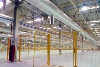
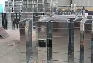
Air duct, as the name implies, is a piping system used for air transportation and distribution.
It can be classified according to cross-sectional shape, material and connection form etc.
According to the cross-sectional shape, the air ducts can be divided into round duct, rectangular duct and oval duct etc.
Among them, the round duct has the smallest resistance but the largest height dimension, and is complex to manufacture, so the most application is rectangular duct.
According to the material, the air duct can be divided into metal duct, non-metal duct, composite duct and Nanosox air duct etc.
According to the connection form, it can be divided into flange connection duct, flangeless connection duct and spiral duct etc.
The flangeless connection duct can be divided into thin sheet flanged duct, transverse duct according to its specific connection form.
The thin sheet flange duct can be divided into combination flange duct and conjoined flange duct according to whether its flange and duct are integrated.
The thin sheet flanged duct can be divided into TDC duct and TDF duct according to the different flange cross-sectional shapes.
TDC duct meaning:
TDC or Transverse Duct Connection refers to a specific type of flange system used in HVAC installations for connecting ductwork. It is preferred for its efficiency, strength, and leak-resistant qualities, making it ideal for high-performance air systems.
TDF duct meaning:
TDF, or Transverse Duct Flange, refers to a type of duct connection system in HVAC (Heating, Ventilation, and Air Conditioning) applications. It’s known for providing airtight seals and easy installation due to its incorporated flange and gasket design.
The thin sheet conjoined flange duct, commonly known as TDC/TDF duct, was invented by Lockformer Company in 1982.
TDC and TDF are two types of duct flange systems used in HVAC. TDC (Transverse Duct Connector) is known for its sturdiness and rigidity, making it ideal for large ductwork. TDF (Transverse Duct Flange) is lighter, easier to install, and more cost-effective, often preferred for smaller ductwork. Both provide secure, airtight connections, but the choice depends on the project’s specific requirements.
This new form of duct began to be used for actual projects in developed countries in Europe and the United States in the 19th, and has gradually been widely used.
China’s national standards Specification for Construction Quality Acceptance of Ventilation and Air Conditioning Engineering (GB50243-2002) clearly states that rectangular ducts can be used in the form of TDC/TDF ducts.
The 07K133 Atlas released subsequently detailed the reference standards for the specific practices of TDC/TDF duct in engineering.
Many projects start to use TDC/TDF ducts, which had good results.
While effectively improving the production efficiency and quality of air ducts, it also greatly enhances the core competitiveness of the enterprise.
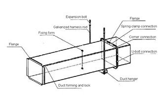
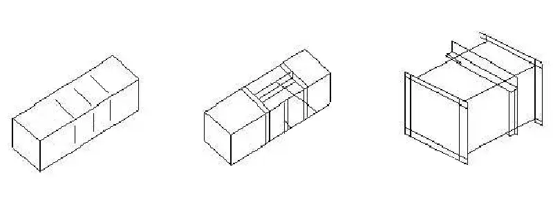
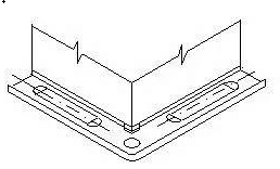
The schematic diagram of the TDC/TDF duct is as follows:
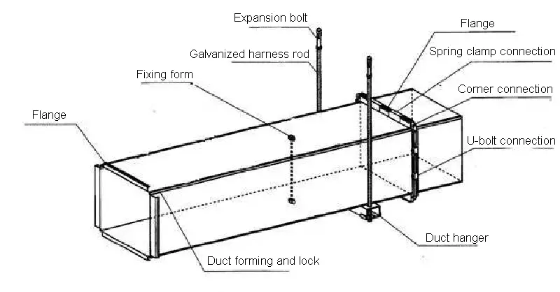
Schematic diagram of TDF/TDC duct
When adopting TDC/TDF duct, the design institute and construction unit shall study and formulate measures to meet the requirements of duct strength and deformation.
The material should comply with the current national standard GB3280 Stainless Steel Cold Rolled Steel Plate.
1) Sheet thickness of galvanized steel duct
| Large side size of duct(mm) | Thickness of galvanized steel(mm) |
| b≤320 | 0.5 |
| 320<b≤630 | 0.6 |
| 630<b≤1000 | 0.75 |
| 1000<b≤1250 | 1.0 |
| 1250<b≤2000 | 1.0 |
| 2000<b≤4000 | 1.2 |
2) Sheet thickness of stainless steel plate duct
| Large side size of duct(mm) | Thickness of stainless steel(mm) |
| b≤500 | 0.5 |
| 500<b≤1120 | 0.75 |
| 1120<b≤2000 | 1.0 |
| 2000<b≤4000 | 1.2 |
1. Sketching of ductwork
With the construction drawings and the actual situation at the site (duct elevation, direction and coordination with other professionals), process sketches are drawn and numbered according to the system.
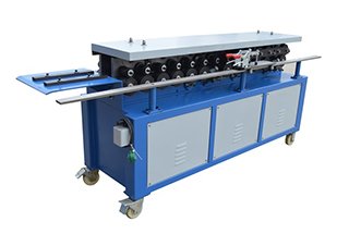
2. The production process of straight duct
→ input the air duct size to the computer according to the sketch
→ galvanized sheet feeding
→ straightening sheet
→ beading
→ notching
→ fixed length sheet cutting
→ joint angle male pittsburgh lock roll forming
→ joint angle female pittsburgh lock roll forming
→ bilateral TDC flange forming
→ folding (according to the size of the duct pipe diameter can be folded into L-shaped, U-shaped, mouth-shaped or unbent flat shape)
→ air duct unilateral reinforcement bar internal reinforcement (low-pressure duct single side flat area >1.2 m2 and medium-pressure duct single side flat area >1.0 m2)
→ joint forming
→ seam closing
→ insert corner mold
→ duct angle reinforcement at all four corners (large side size ≥ 1250mm)
→ internal duct support reinforcement (large side size ≥1250mm)
→ sealant
→ quality control before leaving the factory.
(Note: If it is processed into semi-finished products, the process of forming, joining, arranging the corners, reinforcing the four corners, strengthening the internal support, and sealant of the air duct is completed on the construction site.)
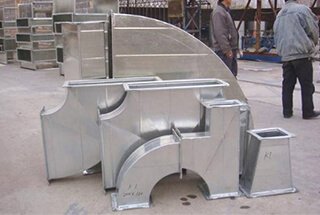
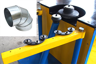
3. The production process of special-shaped pipe (elbow and tee .etc)
→ input the size of the special-shaped pipe to the computer according to the sketch
→ the computer automatically generates the cutting drawing
→ the computer data is transmitted to the controller of plasma cutting machine
→ the plasma cutting machine automatically cuts
→ male and female pittsburgh lock roll forming
→ TDC flange forming
→ folding
→ duct reinforcement by reinforcement strips (low-pressure duct single side flat area >1.2 m2 and medium-pressure duct single side flat area >1.0 m2)
→ joint forming
→ seam closing
→ corner mold insertion
→ duct angle reinforcement at all four corners (large side size ≥ 1250mm)
→ Internal duct support reinforcement (large side size ≥1250mm)
→ sealant
→ quality control before leaving the factory.
(Note: If it is processed into semi-finished products, the process of forming, joining, the corner mold installation, reinforcing the four corners, strengthening the internal support, and sealant of the air duct is completed on the construction site.)
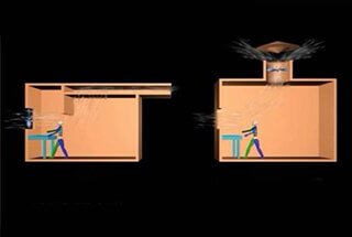
4. Duct reinforcement
①When the large side size of the duct is less than 1000mm, reinforcement of the production line can meet strength requirements.
The press ribs of the production line are arranged regularly, evenly spaced, and no obvious deformation on board surface.
②When the large side size of the duct is more than 1250 mm, the V-shaped reinforcement ribs or harness screws etc. are used to reinforce the internal and external reinforcement of the pipe.
③When the large side size of the duct is more than 2000mm, angle steel, flat steel, steel pipe, Z-groove, reinforcement ribs or harness screw etc. can be used for internal and external reinforcement of the pipe.
④ The height of the angle steel or reinforcing ribs should be less than or equal to the height of the duct flange, the arrangement should be neat, the interval should be even and symmetrical, and the riveting or welding with the duct should be firm.
⑤The inside of the pipe is reinforced with a harness screw, and its special gasket is placed on the inner wall of the duct for external insulation.
For non-insulated duct or insulated duct, it should be placed on the outer wall of the duct, and the threaded screw should be set in the center of the duct.
When the cross-section of the air pipe is large, a harness screw support should be added on both sides near the flange for reinforcement.
⑥ When the duct section is more than 1250×630, in order to keep the adjacent walls perpendicular to each other, it is advisable to use 90°C diagonal supports for reinforcement at the four corners of the duct.
⑦ If the length of the air duct of the medium pressure system is greater than 1250mm, it shall be reinforced with a reinforcement frame.
⑧ The air duct of the purification air-conditioning system shall not be reinforced on the inner wall of the pipe.
The outer wall of the pipe shall be reinforced by triangular ribs, Z-shaped grooves and angle steel etc.
⑨ The reinforcement and rigidity grade of the air duct shall comply with the requirements of Technical Regulations for Ventilation Ducts (JGJ141-2004).
The following tables show the specific regulations:
Reinforced stiffness grade of rectangular duct
| Reinforcement types | Reinforcement specifications (mm) | Reinforcement height(mm) | |||||
| 15 | 25 | 30 | 40 | ||||
| stiffness grade | |||||||
| frame reinforcement | right angle reinforcement | 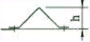 | δ=1.2 | — | G2 | G3 | — |
| Z-shaped reinforcement | 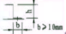 | δ=1.5 | — | G2 | G3 | G3 | |
| δ=2.0 | — | — | — | — | |||
| point reinforcement | screw internal support |  | ≥M8 screw | J1 | |||
| casing inner support | 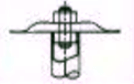 | Ф16×1 casting | J1 | ||||
| reinforcement of compression tendons | compression bar spacing |  | — | J1 | |||
Maximum permissible spacing for transverse reinforcement of rectangular ducts
| Stiffness grade | The side length of the duct | |||||||
| ≤500 | 630 | 800 | 1000 | 1250 | 1600 | 2000 | ||
| allowable maximum spacing | ||||||||
| low-pressure duct | G1 | 3000 | 1600 | 1250 | 625 | Not use | ||
| G2 | 2000 | 1600 | 1250 | 625 | 500 | 400 | ||
| G3 | 2000 | 1600 | 1250 | 1000 | 800 | 600 | ||
| G4 | 2000 | 1600 | 1250 | 1000 | 800 | 800 | ||
| G5 | 2000 | 1600 | 1250 | 1000 | 800 | 800 | ||
| G6 | 2000 | 1600 | 1250 | 1000 | 800 | 800 | ||
| middle-pressure duct | G1 | 1250 | 625 | Not use | ||||
| G2 | 1250 | 1250 | 625 | 500 | 400 | 400 | ||
| G3 | 1600 | 1250 | 1000 | 800 | 625 | 500 | ||
| G4 | 1600 | 1250 | 1000 | 800 | 800 | 625 | ||
| G5 | 1600 | 1250 | 1000 | 800 | 800 | 800 | ||
| G6 | 2000 | 1600 | 1000 | 800 | 800 | 800 | ||
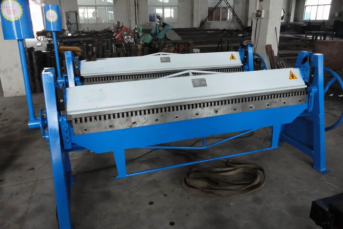
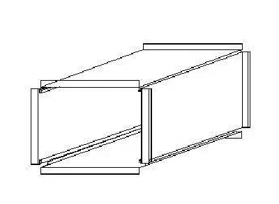
5. Forming of air duct
① Mechanical air duct is connected by joint angle lock former, which strengthens the sealing of the duct.
② The closing seam of the duct is made by hydraulic seam closing machine, which can effectively ensure the tightness and tightness of the joint connection.
And it greatly enhances the beautiful performance of the air duct.
③ The connection between the branch duct and the main duct is made by joint seam or by pulling rivet on the opposite side and the main duct is riveted, and the connection is sealed with glass glue to prevent air leakage.
④ The connection between the duct flanges and the flanges is made using special TDC flange corners, which are inserted into the flanges using a corner insertion machine.
6. Air duct sealing
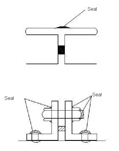
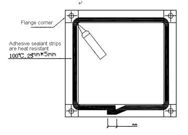
①The TDC/TDF duct should be sealed at the flange corners, inside and outside of the branch duct and main connection.
The low-pressure duct should be sealed 40-50mm into the duct at the fold of the duct joint.
The high-pressure duct should also be sealed at the longitudinal bite and the composite part of the air duct.
② The four flange corners of the TDC/TDF duct must be sealed with glass glue to prevent leakage.
The joint corner bite must be sealed with glass glue to prevent leakage at the place 30mm down from the flange corner and the sealant should be located on the positive pressure side of the duct.
③Flange sealing strips should be installed near the outside of the flange or in the middle of the flange.
When the flange sealing strip overlaps on the flange end face, the figure should be 30-40mm.
④The penetration of the duct during the process of duct reinforcement, connection and installation etc. should be sealed with glass sealant.
⑤The tightness of the air duct should meet the requirements of the following table.
Allowable air leakage of metal rectangular duct
| Pressure (Pa) | Allowable air leakage [m³/(h·m2)] |
| low-pressure air duct (P≤500Pa) | ≤0.1056P0.65 |
| middle-pressure air duct (500<P≤1500 Pa) | ≤0.0352P0.65 |
| high-pressure air duct (P>1500 Pa) | ≤0.0117P0.65 |
① The semi-finished air duct is processed according to the drawn sketch, and is numbered according to the system.
The air duct is formed, reinforced, and connected according to the number on the construction site.
②The air duct flanges are lined with a sealing rubber gasket to enhance the airtightness of the air duct.
③The four corners of the duct are connected by galvanized bolts.
④When the large side size of the air duct exceeds 450mm, in order to strengthen the strength of the flange and the air duct, a flange fixing card is required.
⑤The interval of flange fixing cleat is in accordance with the following table:
| The side length of the duct (mm) | Flange clamp installation diagram | Flange clamp installation requirements | Standard length size of flange cleat |
| 0→200 |  | not need to add | 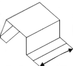 120-150mm |
| 250-550 |  | add one to the center | |
| 600-1000 |  | add two equidistant | |
| ≥1050 | 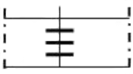 | add one with spacing below 150 |
1) Air duct assembling
2) Install the flange corner

① Corner insertion
② Corner fixing

③ Apply leak-proof glue and install flange sealant
④ Screw connection at four corners
⑤ Mount the flange cleat
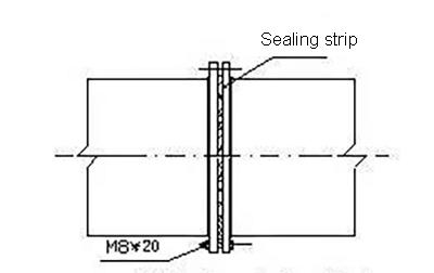
The four corners of the TDF/TDC flange are connected by galvanized bolts.
There are two types to connect the flange edge: flange spring clamp connection and top wire clamp connection.
The installation distance must be less than or equal to 150mm.
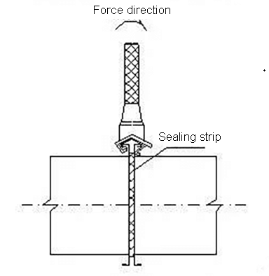
Flange spring clamp connection (commonly known as hook code, flange buckle)
Flange spring clamp can be produced by a TDF/TDC flange forming machine, and its plate thickness is 1mm.
It is suitable for the connection of TDC/TDF ducts with air pressure less than or equal to 1500Pa and side length less than or equal to 1350mm.
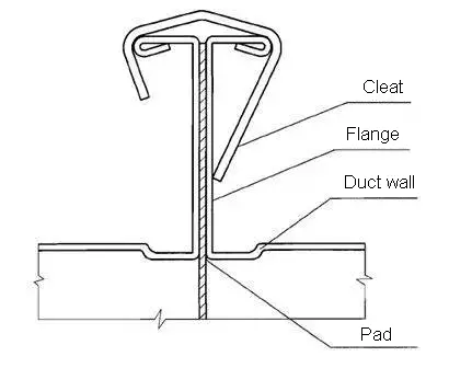
Installation diagram of the flange spring clamp
The u-bolt connector needs to be customized or purchased in the market, and the thickness of the plate is 3mm.
It is suitable for the connection of TDF/TDC duct with air pressure less than or equal to 1500Pa and side length longer than 1350mm.
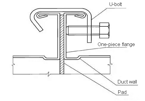
Installation diagram of U-bolt connection
In summary, it can be seen that, as a new type of air duct, the TDF/TDC duct produced on a large scale in the factory has significant advantages in the application of ventilation and air conditioning engineering.
Its convenient and efficient construction technology effectively reduces the construction cost of the enterprise, speeds up the construction progress, improves the construction quality, and reduces the noise pollution and paint pollution on the construction site.
However, due to the insufficient flange strength, traditional angle flange ducts are still required for large-side air ducts with a long side of more than 2000mm and high-pressure ducts with the air pressure of more than 1500Pa.
In practical applications, the TDC/TDF duct or angle flange duct should be reasonably selected according to the characteristics of the project.

As the founder of MachineMFG, I have dedicated over a decade of my career to the metalworking industry. My extensive experience has allowed me to become an expert in the fields of sheet metal fabrication, machining, mechanical engineering, and machine tools for metals. I am constantly thinking, reading, and writing about these subjects, constantly striving to stay at the forefront of my field. Let my knowledge and expertise be an asset to your business.