1. Field Measurement for Ventilation System Installation
Distances and Spatial Relationships
- Distances to Structural Elements: Measure the distances between the ventilation system location and critical structural elements such as columns, partition walls, reserved holes, and outer walls.
- Height Measurements: Measure the height from the floor and ground to the roof to ensure adequate vertical space for the ventilation system.
Wall and Opening Dimensions
- Wall Thickness: Measure the thickness of both external and partition walls.
- Reserved Holes: Measure the size of any reserved holes that will be used for duct passage.
- Doors and Windows: Measure the width and height of doors and windows to ensure the ventilation system does not obstruct these openings.
Structural and Equipment Details
- Column Dimensions: Measure the cross-sectional size of any columns within the installation area.
- Beam and Roof Distance: Measure the distance between the bottom of beams and the flat roof to ensure there is enough clearance for the air ducts.
- Platform Height: Measure the height of any platforms that may affect the installation of the ventilation system.
Equipment and Connection Points
- Production Equipment: Measure the size, position, and height of any production equipment that the ventilation system will interact with.
- Air Duct Equipment: Measure the size and relative position of the air duct equipment and the connection ports for the ventilation components.
Foundation and Support Measurements
- Foundation Size: Measure the size, height, and distance from the wall of the foundation or support structures for the ventilation equipment.
2. Actual Sketching
Through the above work, draw processing installation sketches.
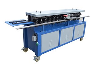
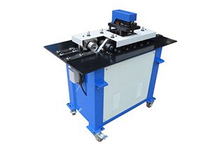
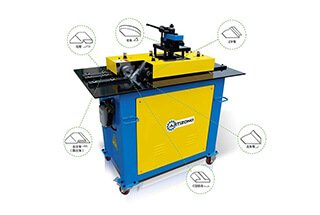
3. Sheet Correction
- Steel Coil Leveling Machines:
Steel coil leveling machines are essential tools in the sheet metal processing industry. They are commonly utilized to straighten coils through a series of repeated bends with multiple rollers. These machines ensure that the steel coils are flattened and free from any residual stress, which is crucial for further processing and fabrication.
- Manual Hammering Correction:
Usually, flat plates are corrected for bending deformations using manual hammering correction methods. The choice of hammer and technique depends on the thickness of the sheet material:
- For Sheets Less Than 0.8mm Thick:
- A large, soft, flat-head wooden hammer should be used. This type of hammer is effective for fast flattening and provides high efficiency without damaging the thin sheet.
- For Sheets with Thickness ≥ 0.8mm:
- A steel flat-head hammer is recommended. This hammer provides the necessary force to smooth thicker sheets effectively.
- Identifying Deformation Characteristics:
Based on the unevenness of the sheet, it is crucial to identify deformation characteristics such as warpage or unevenness. Once identified, an iron platform should be used for smoothing the sheet. This ensures that the sheet is uniformly flat and ready for further processing.
4. Underlining
- Determine Thickness: The thickness of the plate should be determined according to the design size of the air duct.
- Select Number of Bend Pipes: Based on the design, select the appropriate number of bend pipes.
- Determine Interface Mode: Choose the interface mode that best suits the design requirements.
- Cutting and Unfolding Methods: Use calculation and unfolding methods to cut the material accurately. Define the cutting line and make precise cutting marks to ensure the material is cut correctly and fits the design specifications.
5. Unfolding
1. Select Appropriate Model Material
When selecting the material for the model, it is crucial to choose one that is not too thick, ideally within the range of 1 to 3mm. The material should also be free from curling or deformation. Preferred materials include:
- Kraft Paper: Known for its durability and flexibility.
- Linoleum Paper: Offers a smooth surface and consistent thickness.
- Soft Plastic Sheet: Provides flexibility and ease of handling.
- Thin Iron Sheet: Offers rigidity and can be shaped precisely.
2. Calculate Appropriate Length of Sample Plate
The length of the circular tube sample should be calculated using the following formula:Length=(Outer Diameter of Pipe+Thickness of Sample Material)×𝜋Length=(Outer Diameter of Pipe+Thickness of Sample Material)×πHowever, it is important to account for seasonal and material influences that may affect the actual circumference of the pipe. For instance:
- Winter: Linoleum paper may become harder and not fit tightly on the outer wall of the tube, necessitating an increase in the model length.
- Summer: Linoleum paper may become softer and stretch, requiring a reduction in the unfolded length of the model.
These adjustments should be made before drawing the expansion curve, as neither growth nor reduction can be carried out afterward.
3. Check Actual Volume of Review
After creating the model, it is essential to verify its shape and size by wrapping it around the outer wall of the pipeline and checking the volume. The model should fit closely to the pipe wall, with the two ends meeting without any gaps or overlaps. There are three methods for expanding the model:
- Parallel Line Expansion: Suitable for simple shapes where lines remain parallel.
- Radiation Expansion: Used for conical or tapered shapes where lines radiate from a point.
- Triangle Expansion: Applied for complex shapes involving triangular sections.
Blanking is a critical step in the sheet metal fabrication process, where the material is cut into a specific shape or size. This process involves marking the sheet material with the unfolding drawing and the clear outline of the blank size before proceeding to the shearing step. Here are the detailed steps and considerations for effective blanking:
1. Marking and Scribing
Before any cutting begins, it is essential to mark the sheet material accurately:
- Unfolding Drawing: Mark the sheet with the unfolding drawing to ensure the correct dimensions and shape.
- Clear Outline: Draw a clear outline of the blank size on the sheet material.
2. Shearing
Shearing is the process of cutting the sheet material. The method of shearing depends on the thickness of the material:
- Hand Shearing: Suitable for steel sheets with a thickness of less than 0.8mm.
- Mechanical Shearing: Used for thicker sheets, as hand shearing would be inefficient and potentially inaccurate.
3. Cutting Process
(1) Alignment and Tangent Marking
- Precise Alignment: Align the scribing line on the plate accurately before cutting.
- Tangent Mark: Ensure there is a clear tangent mark on the steel plate to guide the cut.
(2) Cutting Execution
- Vertical Holding: After marking, hold the steel plate vertically and cut along the tangent line.
- Reducing Resistance: Lift the cut sheet upward with your hand during the cutting process to reduce resistance and ensure a smoother cut.
(3) Cutting Curves and Corners
- Avoiding Line Marks: When cutting curves, fold lines, and corners, avoid cutting the line marks on the sheet.
- Scissors Positioning: Align the end of the scissors with the top of the corner and avoid positioning it too far away.
(4) Cutting Holes and Circles
- Hole Cutting: Make an initial hole, insert the scissors, and cut counterclockwise along the line.
- Circle Cutting:
- For smaller diameters, use curved scissors and cut counterclockwise.
- For larger circles with a smaller margin, cutting clockwise is permissible.
4. Post-Shearing
- Beveling: After completing the shearing, use scissors or a chamfering machine to bevel the end of the sheet. This step is crucial to remove sharp edges and prepare the sheet for further processing.
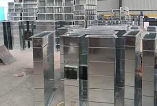
7. Closing of the air duct
1. Selection of Plate Thickness
Choose the plate thickness based on the specifications and sizes of the air duct. Ensure to leave a margin for unloading to accommodate any adjustments during the manufacturing process.
2. Precision in Line Drawing
The line drawing process must be precise to ensure straight angles, flat lines, and accurate measurements. Frequently check geometric sizes and ensure all necessary lines, such as cutting lines, chamfering lines, folding lines, flanging lines, hole lines, and closing lines, are drawn accurately.
3. Cutting and Chamfering
Cutting and chamfering must be executed with high precision to minimize errors. After cutting, chamfer the edges using a chamfering machine or iron scissors before closing the edges. Ensure there is no overlap or flanging during the operation to maintain the integrity of the air duct.
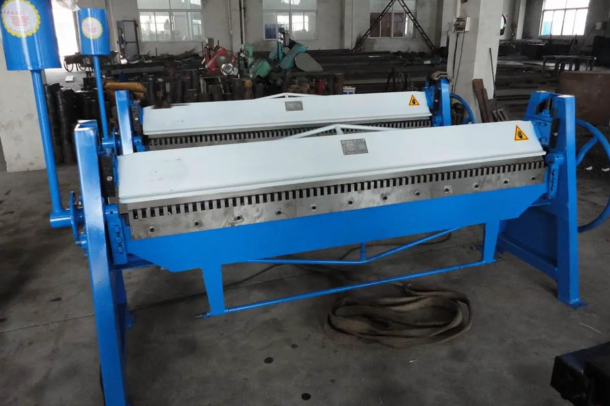
4. Folding the Plate
Place the plate on the folding machine according to the drawn folding line and fold it to the desired angle. During the operation, align the folding line with the upper and lower molds of the square folding machine to ensure accuracy.
5. Creating Round Air Ducts
To create a round air duct, use a clapper to shape the edge into an arc. Circle the bite and adjust the arc to make it uniform. This ensures a smooth and consistent round shape for the air duct.
6. Seaming
After folding or rounding the steel plate, use a seaming machine or manual seaming. Apply even pressure to avoid uneven seams or bursting. Proper seaming ensures the durability and functionality of the air duct.
7. Seam Staggering
The seams of the air duct plates should be staggered to avoid cross-shaped seams, which can weaken the structure. Proper seam staggering enhances the strength and stability of the air duct.
8. Common Forms of Seams
- Single Seam: Used for splicing and closing circular ducts.
- Corner Seams, Joint Angle Seams, and Snap Button Seams: Suitable for rectangular air ducts or accessories.
- Vertical Seams: Used for round elbows.
Steel plate duct bite joint:
- Thickness ≤ 1.2mm: Can be connected by bite.
- Thickness > 1.2mm: Should be welded. Flange butt welding should adopt gas welding.
- Galvanized Mesh Panels: Should be bite-joined or riveted.
- Plastic Composite Panel Air Ducts: Use bite and riveting methods to avoid burning the plastic layer by gas welding and electric welding. The bite machine must not have sharp edges to avoid scratches. If the plastic layer is damaged, it should be painted and protected in time.
Stainless steel plate duct bite joint:
- Wall Thickness ≤ 1mm: Can use bite connection.
- Wall Thickness > 1mm: Use arc welding or argon arc welding. Gas welding is not allowed. The electrode should be of the same type as the base material, and the mechanical strength should not be lower than the minimum value of the base material.
Aluminum plate air duct bite joint:
- Wall Thickness ≤ 1.5mm: Can be connected by bite.
- Wall Thickness > 1.5mm: Use gas welding or argon arc welding. There should be no scratches on the surface of the aluminum air duct and accessories. When setting out, use color pencils or colored pens. The bite or shaping of the air duct should be done with a wooden hammer or wooden square ruler to avoid deformation of the bite seam.
9. Bite Width and Quantity
The width of the bite is determined by the thickness of the air duct material. Typically, for single flat bites, single vertical bites, and single angle bites, the width of the bite on the first plate should be consistent. On the second plate, the bite width should be doubled, resulting in a total allowance for the bite equal to three times the bite width. The quantity of the bite should be maintained on both sides as required by the design specifications.
10. Bite Processing
Mechanical bite processing primarily involves the use of various bite machines. For curved lines or solid bites, it is recommended to use wooden blocks and wooden hammers instead of steel hand hammers to extend the edge of the board. This practice helps avoid visible marks on the material. The joint of the bite should be tight, with no half bites or cracking.
For straight pipes, the joints should be staggered in the longitudinal bite seam. This is crucial because air ducts often include elbows, tees, and other fittings. A round elbow, for instance, is composed of several short inclined tubes, and the single bite is formed in one direction when making the elbow. Consequently, the bite seam of each section is in opposition, which is necessary for the production of elbows and is not restricted by this regulation.
The width of the bite seam should be uniform to prevent inconsistencies, such as a wide bite seam at one end and a narrow bite seam at the other. Such inconsistencies can affect both the appearance and the structural integrity and tightness of the bite seam.
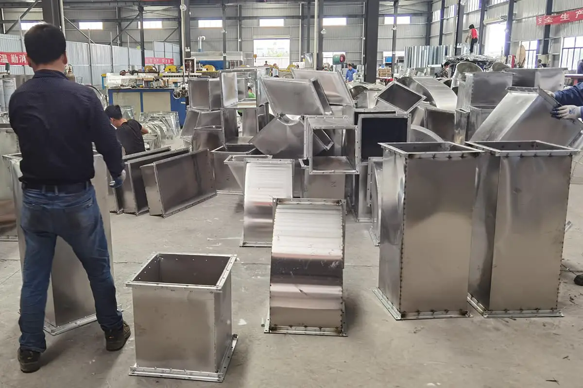
8. Welding Forms of Air Ducts
1. Butt Welding
Butt welding is utilized for joining plates or for creating horizontal and vertical closed seams. This method ensures a strong and seamless connection between two metal pieces, making it ideal for applications where structural integrity is paramount.
2. Lap Welding
Lap welding is commonly used for the longitudinal closed seams of rectangular ducts or pipe fittings, as well as the elbows and corner joints of tees in rectangular ducts. The general overlap is 10mm, and the overlap area should be marked before welding. Spot welding should be performed along the marked line, followed by smoothing the weld with a small hammer before continuous welding. This method ensures a strong bond and minimizes the risk of leaks.
3. Flange Welding
Flange welding is employed for closing joints without flanges, round pipes, and elbows. When dealing with thin sheets, gas welding can be used due to its precision and control over heat input, which prevents warping and ensures a clean weld.
4. Fillet Welding
Fillet welding is used for the longitudinal closed seams of rectangular air ducts or pipe fittings, the turning joints of rectangular elbows and tees, and the closed seams of round rectangular air duct heads. This type of welding provides a strong joint and is often used in applications where the weld is subjected to various stresses.
5. Carbon Steel Duct Welding
For carbon steel ducts, a DC welding machine should be used. Prior to welding, the area must be cleaned of dirt, oil marks, and rust. Both spot welding and continuous welding require the removal of oxides to ensure a clean weld. The gap should be minimized, and any nodules at the manual spot welding position should be promptly removed. After welding, electrode slag and residual welding wire in the seam and nearby areas should be cleaned to maintain weld quality.
6. Stainless Steel Duct Welding
Before welding stainless steel ducts, grease and dirt must be cleaned from the welding seam area using gasoline or acetone to prevent air holes and sand holes. During arc welding, white powder should be applied to both sides of the weld to prevent spatter from adhering to the plate surface. Post-welding, the slag should be removed, and the metallic luster should be restored with a copper wire brush. The weld should then be pickled with a 10% hydrochloric acid solution and washed with hot water to ensure a clean and corrosion-resistant weld.
7. Aluminum Air Duct Welding
For aluminum air ducts, the welding area must be degreased and the oxide film removed using a stainless steel wire brush. Welding should be performed within 2 to 3 hours after cleaning. Post-welding, degreasing should be done using aviation gasoline, industrial alcohol, carbon tetrachloride, or other cleaning agents and wood chips to ensure a clean weld.
8. Gas Welding of Thin Steel Plate Ducts
Gas welding of thin steel plate ducts is typically performed from left to right. The flame direction should be controlled to ensure balanced heat distribution on both sides of the weld. The flame should move forward smoothly and evenly, with a uniform speed of the welding wire into the molten pool to achieve a consistent weld.
9. Weld Quality Requirements
The surface of the weld should be free of defects such as cracks, burn-through, or missing welds. Longitudinal welds should be staggered to distribute stress evenly. The welding seam should be smooth, and spot welding should be symmetrically alternated to prevent deformation. The width of the welding seam should be uniform. After welding, the weld should be cleaned to remove welding slag, ensuring a clean and strong joint.
9. Flange production
1. Distance Between Bolts and Rivet Holes
- Low-Pressure System: The distance between the bolts and rivet holes on the air duct flange should not exceed 150mm.
- High-Pressure System: The distance should not be larger than 100mm.
- Rectangular Duct Flange: The four corners must have screw holes.
2. Flange for Low, Medium, and High-Pressure Systems
- Low and Medium-Pressure Systems: The distance between the bolts and rivets should be less than or equal to 150mm.
- High-Pressure System: The distance should be less than or equal to 100mm.
- Rectangular Flange: The four corners must be reinforced with bolts or rivets.
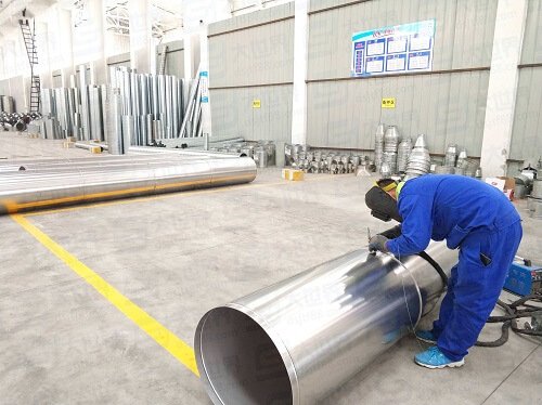
3. Round Flange Production
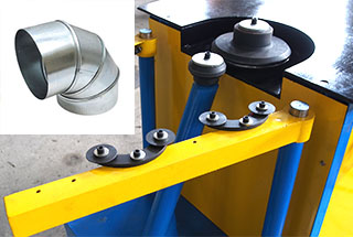
- Material Processing: Angle iron or flat iron is rolled into a spiral shape using a steel coiling machine.
- Cutting and Leveling: The rolled steel strip is cut and leveled on a platform.
- Welding and Drilling: After adjustment, welding and drilling are performed. Holes must be evenly distributed along the circumference for interchangeability.
4. Rectangular Flange Production
- Material: Made from four pieces of angle iron.
- Marking and Blanking: Ensure the inner edge of the flange after welding is not smaller than the outer dimension of the air pipe and within acceptable deviation.
- Cutting and Punching: Must be done using a material cutting machine or hand saw, not oxygen and acetylene cutting. The angle steel fractures must be smooth, and burrs must be removed.
- Welding: Performed on a platform. The angle of the flange must be measured and adjusted after spot welding to ensure equal diagonal lengths.
- Screw Holes: Accurate location is crucial for smooth installation. The drilling method is the same as for circular air pipe flanges.
5. Aluminum Plate Flange Production
- Material: Made from flat aluminum or angle aluminum.
- Substitution with Angle Steel: If angle steel is used, insulation and anti-corrosion treatment are necessary to prevent electrochemical corrosion.
- Surface Treatment: Typically, the angle steel flange is galvanized or sprayed with insulating paint.
6. Flange and Air Pipe Connection
- Riveting: Must be firm and without leaks. The flanging must be smooth, close to the flange, with a width of not less than 6mm, and without cracks or holes.
- Welding: The end face of the air pipe must not be higher than the flange interface plane. For dust removal systems, full inside welding and intermittent outside welding are required. The end face must be at least 5mm from the flange interface plane.
- Anti-Corrosion: If the flange is made of carbon steel, anti-corrosion treatment is required as per design requirements. Rivets must be made of the same material as the air duct or be non-corrosive.
Quality Acceptance of Flange Production
- Welding Seam: Should be well-fused without false welding or holes.
- Flatness Deviation: Permissible deviation for flange flatness is 2mm.
- Screw Hole Arrangements: Must be consistent and interchangeable for flanges of the same specification processed in a batch.
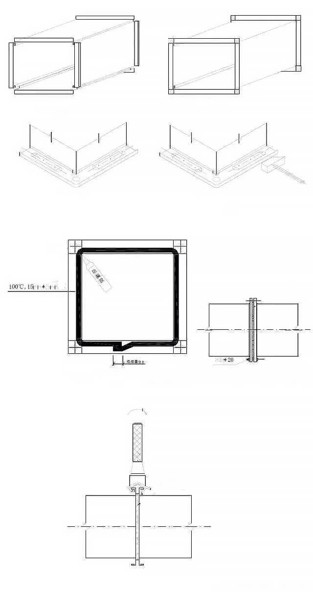
10. The Air Duct No-Flange Connected Production
1. Circular Air Pipes
Most circular air pipes utilize either direct socket connections or core tube connections. Here’s a detailed explanation of these methods:
Direct Socket Connection
- Method: The ends of two air pipes are directly inserted into each other.
- Advantages: Simple and quick to assemble.
- Considerations: Ensure a tight fit to prevent air leakage.
Core Tube Connection
- Method: A core tube acts as an intermediate connector. Two air pipes are inserted at both ends of the core tube.
- Insertion Depth: The insertion depth must be at least 20mm to ensure a secure connection.
- Fixation: Use pull rivets or self-tapping screws to fix the connection between the air pipe and the core tube.
- Sealing: Apply a sealant to the joint to ensure it is tightly sealed, preventing any air leakage.
2. Rectangular Air Pipes
The connection of rectangular air pipes typically involves various methods to ensure a secure and airtight connection:
Connection Methods
- Inserts: Metal or plastic inserts are used to join the ends of the air pipes.
- Bites: Mechanical bites or crimps are employed to secure the connection.
- Metal Spring Clips: These clips provide a strong and flexible connection.
- Mixed Connections: A combination of the above methods may be used for enhanced stability and sealing.
Key Considerations
- Accuracy: The size of the connections must be precise to ensure a proper fit.
- Regular Shape: The shape of the connections must be regular to avoid any gaps or misalignments.
- Tight Interface: The interface must be tight to prevent any air leakage.
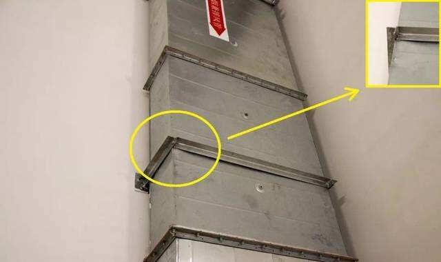
11. Duct Reinforcement
(1) Reinforcement Techniques:
Joint height reinforcement technique (using a standing bite). Reinforcing the air duct with an angle steel ring around the circumference. Reinforcing the larger side of the duct with angle steel. Longitudinally reinforcing the inner wall of the air duct with ribs and reinforcing the steel plate of the air duct with rolled grooves or crimped ribs.
Requirements for Air Duct Reinforcement Quality:
The air duct must be firmly reinforced, and for it to be considered excellent, it must be neat.
The spacing between each reinforcement must be appropriate, uniform, and parallel.
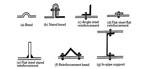
(2) Forms and Requirements for Air Duct Reinforcement:
The air duct can be reinforced in the form of corrugated bars, standing bars, angle steel (for both internal and external reinforcement), flat steel (using vertical reinforcement), reinforcing bars, and internal tube support.
Refer to Figure 4.3.1.11.
Figure 4.3.1.11 Reinforcement form of air duct
(3) Reinforcement using corrugated bars or wires should be arranged in a regular pattern with uniform intervals, and there should be no obvious deformations on the surface of the duct.
(4) Angle steel and reinforcement ribs should be arranged neatly and symmetrically, with a height not exceeding the flange width of the air duct. The riveting of angle steel, reinforcement ribs, and air duct should be secure, with even spacing not exceeding 220mm, and the two intersections should be joined as one.
(5) Supports and air ducts should be fixed securely, with uniform spacing between each support point, or the edge or flange of the air duct, not exceeding 950mm.
(6) For medium-pressure and high-pressure system air duct sections with a length greater than 1250mm, reinforcement bars should also be used. The metal air duct of the high-pressure system should have reinforcement or reinforcing measures to prevent bursting at the single bite seam.