Minimize Welding Stress: Causes and Elimination
1. What is welding stress Welding stress refers to the stress generated during the welding process in welded components. This stress is caused by the thermal process of welding and [...]

To address the issue of cracking in wire-cut cemented carbide products, the microstructure of the alloy surface was analyzed by adjusting wire-cutting processing parameters, based on the current situation of the company’s products. Through experimental comparison, the main factors causing cracks were identified and solutions were proposed.
WEDM (Wire Electric Discharge Machining) is widely used in the processing of cemented carbide as mold material and wear-resistant parts, particularly for workpieces with small size, complex shape, and unsuitable for machining by grinding wheel. This process improves processing efficiency compared to traditional methods.
However, when using WEDM for machining alloy parts with complex structures, the impact on the microstructure area of the alloy surface is often overlooked. This can result in significant changes to the microstructure of the machined surface, affecting the performance of the cemented carbide workpiece.
Research has shown that WEDM can cause micro cracks and other defects on the surface of die products, impacting their performance. To address this issue, researchers have proposed improvement measures, such as using composite cutting fluid in the first two cuts and kerosene in the final finishing. This has been demonstrated to reduce the surface roughness (Ra) to less than 1mm for cemented carbide YG8.
Liu Yike analyzed the test results of WEDM machining cemented carbide molds based on the EDM principle and found that while increasing pulse width improves machining efficiency, cracks can occur beyond a certain value. Luo Binhui and others conducted a comparative test on EDM processes that may affect cracks in cemented carbide template cutters and found solutions to the crack problem.
This post builds upon previous research and company experience to further analyze the mechanism of cracks in cemented carbide products caused by wire cutting. By changing the electrical parameters of wire EDM, the impact of wire cutting electrical parameters on microstructure cracks of the alloy surface is analyzed, and methods to reduce and avoid cracks are proposed.
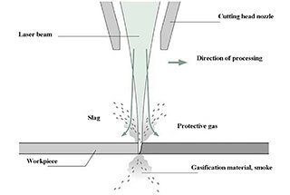
Wire cutting is distinct from conventional cutting in that it does not directly come into contact with the workpiece. Instead, it relies on the continuous pulse spark discharge that occurs between the cutting wire and the workpiece. This discharge uses the high temperature generated during the partial and instantaneous spark to gradually etch away the metal materials.
The spark discharge is carried out in an insulated liquid medium, such as an emulsion. The current density in the discharge area during wire cutting can reach as high as 10,000 A/mm2, and the temperature can reach as high as 10,000-12,000 ℃. The dielectric liquid used in the process cools rapidly.
The EDM energy creates a non-uniform, time-varying temperature field on the material surface, leading to significant thermal stress and strong thermal shock properties. In WEDM, the machining surface experiences rapid heating and cooling, causing uneven material expansion and contraction and potentially leading to great thermal stress.
This is particularly problematic when machining hard and brittle materials, such as cemented carbide and cermet, and can result in surface cracks if the electrical parameters are not chosen correctly and the thermal stress exceeds the material’s strength limit.
Microcracks often appear on the surface due to the generation of tensile stress caused by the instantaneous high temperature and rapid cooling during EDM. These cracks usually only occur in the melting layer, but can expand to the heat-affected layer when the pulse energy is high (during rough machining).
The discharge energy received by the workpiece has a significant impact on the formation of microcracks: larger energy results in wider and deeper cracks, while smaller pulse energy leads to narrower and shallower cracks and fewer and smaller hole distributions.
The sensitivity of different workpiece materials to cracks varies with the material’s thermal conductivity, with brittle materials like cemented carbide being particularly prone to surface microcracks.
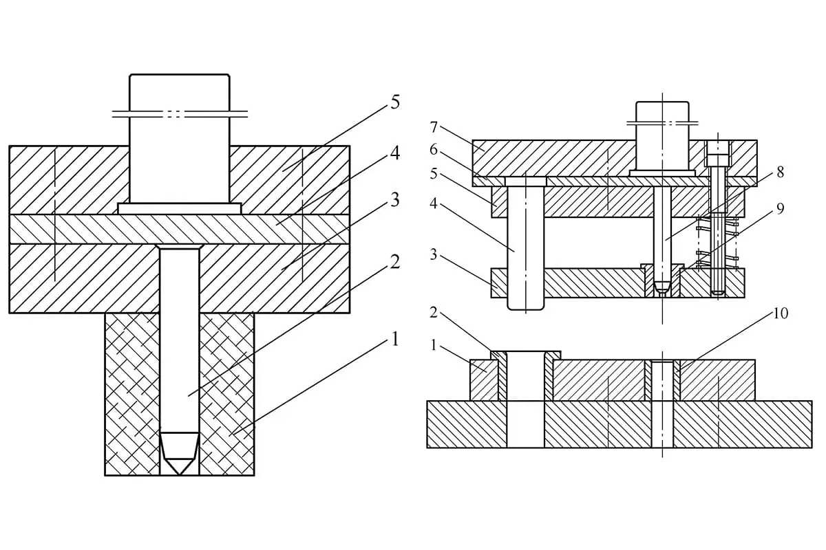
A visualization of the wire cutting discharge process is shown in Figure 1.
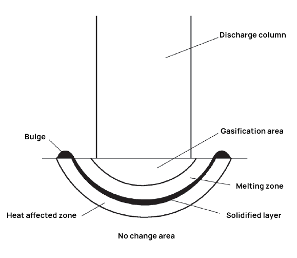
Fig. 1 wire cutting discharge
According to the thermal stress model, the peak stress is directly proportional to the amount of heat that enters the material. This relationship is consistent under similar conditions and is directly related to the input energy of the electric pulse.
As the input power increases, the material absorbs more heat.
Therefore, the greater the power is, the greater the stress is, and the easier it is to produce cracks. Ignoring the loss of energy, the energy acting on the workpiece in the machining process can be simplified as wire cutting discharge pulse energy, which is

Where,
The energy (w) of a discharge pulse during wire cutting is proportional to the discharge voltage (U), discharge current (I), and discharge duration (pulse width, tK). It has been observed that when the pulse width is constant, an increase in discharge voltage and current will intensify the generation and spread of microcracks. Conversely, if the discharge voltage and current are fixed, an increase in pulse width will have the same effect.
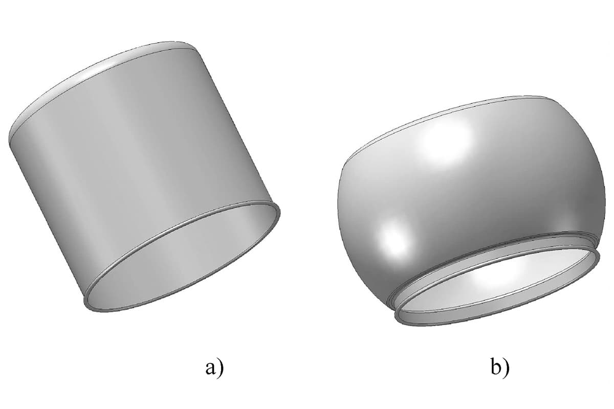
Cemented carbide shaft sleeves are highly valued for their hardness, wear resistance, and corrosion resistance, making them popular in the oil production industry. They are used in various components such as electric submersible pump motors, centrifugal pumps, protectors, separator shafts, and sliding bearing sleeves, motor shaft sleeves, stabbing bearing sleeves, thrust bearing sleeves, and sealing shaft sleeves. These sleeves serve crucial functions, such as providing rotating support, stabling, thrust, and sealing.

Fig. 2 conventional cemented carbide shaft sleeve
In the test, the medium wire cutting equipment used was the CTP350.
The cutting fluid employed was an emulsion with a concentration of 8% and the cutting wire used was a 0.18mm diameter molybdenum wire.
Each time, only one piece was clamped for processing.
Please refer to Table 1 for the wire cutting processing parameters.
| Test group No | NO. | Voltage/V | Current/A | Pulse duration/μs | Pulse interval/μs | Wire feeding speed/(m/s) |
| One | 1 | 100 | 1.5 | 40 | 320 | 15 |
| 2 | 100 | 1.5 | 36 | 282 | 15 | |
| 3 | 100 | 1.5 | 24 | 192 | 15 | |
| 4 | 100 | 1.5 | 12 | 96 | 15 | |
| Two | 5 | 100 | 3.5 | 20 | 160 | 15 |
| 6 | 100 | 2.8 | 20 | 160 | 15 | |
| 7 | 100 | 2.4 | 20 | 160 | 15 | |
| 8 | 100 | 2.0 | 20 | 160 | 15 | |
| Three | 9 | 120 | 2.0 | 20 | 160 | 15 |
| 10 | 110 | 2.0 | 20 | 160 | 15 | |
| 11 | 90 | 2.0 | 20 | 160 | 15 | |
| 12 | 70 | 2.0 | 20 | 160 | 15 | |
| Four | 13 | 100 | 2.8 | 16 | 128 | 15 |
| 14 | 80 | 1.0 | 6 | 48 | 6 | |
| 15 | 50 | 0.3 | 4 | 32 | 3 |
1 # ~ 4 # product metallographic photos are shown in Fig. 3 ~ Fig. 6.
It is observed that as the pulse width decreases, the microcracks on the alloy surface become progressively smaller. At a pulse width of 40 milliseconds, the depth of microcracks reaches 15 millimeters. However, with a pulse width of 12 milliseconds, there are essentially no microcracks present.

Fig. 3 #1 metallographic photos of products

Fig. 4 #2 metallographic photos of products

Fig. 5 #3 metallographic photos of products

Fig. 6 #4 metallographic photos of products
5# ~ 8# product metallographic photos are shown in Fig. 7 ~ Fig. 10.
It has been observed that the crack depth increases as the processing current increases. At 3.5A, the crack depth exceeds 30mm; when the processing current is 2.8A, the crack depth is equal to 30mm; and when the processing current is 2.4A, the crack depth is 20mm. At 2.0A, the crack depth is at its lowest, measuring 10mm.

Fig. 7 #5 product metallographic photos

Fig. 8 #6 metallographic photos of products

Fig. 9 #7 metallographic photos of products

Fig. 10 #8 metallographic photos of products
9# ~ 12# product metallographic photos are shown in Fig. 11 ~ Fig. 14.
It has been observed that when the current is set to 2A and the pulse width is 20ms, the processing voltage ranges from 70 to 120V. No alloy microcracks were found in the cutting section. This indicates that, with constant current and pulse width, the effect of voltage on alloy microcracking is negligible.

Fig. 11 #9 metallographic photos of products

Fig. 12 #10 metallographic photos of products

Fig. 13 #11 metallographic photos of products

Fig. 14 #12 metallographic photos of products
13# ~ 15# metallographic photos of products are shown in Fig. 15 ~ Fig. 17.
The surface quality of products has significantly improved through multiple cutting processes, reducing the depth of microcracks.
With medium wire walking cutting and processing twice, the depth of microcracks in the product is reduced to within 15mm.
And with medium wire walking cutting and processing three times, the depth of microcracks is further reduced to within 10mm.
Two cutting processes have met the current requirement that the depth of microcracks in cemented carbide shaft sleeve products should be less than 20mm.

Fig. 15 #13 metallographic photos of products

Fig. 16 #14 metallographic photos of products
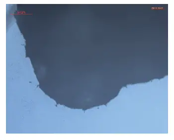
Fig. 17 #15 metallographic photos of products
During EDM (Electrical Discharge Machining), the workpiece surface experiences a rapid temperature change due to the abrupt alternation of hot and cold. This results in a strong transient thermal shock process with a fast speed and large amplitude.
When machining brittle materials like cemented carbide, cracks can be reduced or prevented by reducing the stress amplitude and its time-varying thermal shock. This can be achieved by various methods that limit the thermal shock.
The pulse width and processing current have a significant impact on the surface microcracks of the alloy. A wider pulse width and higher current lead to deeper cracks. However, the effect of voltage on the surface microcracks is not significant.
Microcracks were not observed when the pulse width was set at 12ms. To avoid cracks, it is recommended to avoid processing current above 2A when selecting electrical parameters.
To minimize thermal stress and its impact on the workpiece, high peak narrow pulse electrical parameters should be used and the temperature field superposition effect should be utilized. This will cause the workpiece material to vaporize, resulting in a higher gasification heat that removes most of the heat and prevents overheating of the workpiece surface.
Multiple cutting is an effective method to reduce and eliminate surface microcracks.

As the founder of MachineMFG, I have dedicated over a decade of my career to the metalworking industry. My extensive experience has allowed me to become an expert in the fields of sheet metal fabrication, machining, mechanical engineering, and machine tools for metals. I am constantly thinking, reading, and writing about these subjects, constantly striving to stay at the forefront of my field. Let my knowledge and expertise be an asset to your business.