All semi-automatic carbon dioxide welding machines are equipped with voltage and current adjustment knobs. However, the voltage adjustment of tap-type carbon dioxide welding machines is a change-over switch.
In the case of an integrated welding machine (where the wire feeder is installed inside the host), the current adjustment knob is installed on the host panel.
In the case of a split-type welding machine (where the wire feeder is independent and connected to the host through cables), the current adjustment knob is installed on the wire feeder.
There are two methods to adjust the voltage for carbon dioxide welding machines:
- For thyristor rectifier and inverter welding machines, a potentiometer is used.
- For tap-type welding machines, voltage adjustment is made through the transfer switch.
The first requirement for ensuring stability during the CO2 welding process is that the feeding speed of the welding wire must be equal to the melting speed.
Related reading: Manual Arc Welding vs CO2 Gas Shielded Welding
The energy required to melt the welding wire is provided by the welding machine. The higher the output power of the welding machine, the faster the welding wire melts.
In the case of a thyristor rectifier welding machine, the output power is adjusted by controlling the conduction angle of the thyristor. For an inverter welding machine, the output power is adjusted by controlling the pulse width. For a tap welder, the output voltage is adjusted.
As per conventional wisdom, power is the product of voltage and current. Thus, adjusting the output power of the welding machine is equivalent to adjusting the welding current.
The welding current in carbon dioxide welding is adjusted by controlling the wire feeding speed. This can be explained from two perspectives:
- The current is generated in a closed loop (circuit).
- Current is a function of time.
In an open circuit, no matter how high the voltage is, the current is always zero. In this case, the voltage at the terminals of the circuit is the electromotive force (EMF) of the power supply, which can be measured using a voltmeter at points A and B. This is known as the no-load voltage of the welding machine.
If a loop cannot be formed in the circuit, there will be no current flowing and no voltage generated across both ends of resistance R. Resistance R represents the sum of the internal resistance of the power supply and the voltage drop loss of the transmission cable in the welding arc source system. The power supply’s internal resistance is caused by the transformer’s leakage reactance, the rectifier components’ conduction angle adjustment, and the switching device’s pulse width.
However, if two points A and B are short-circuited or a resistance RH is indirectly connected at these points, current will be generated in the circuit. RH refers to the voltage drop generated at the moment when the welding current is short-circuited with the workpiece through the arc and droplet, which is also known as the load resistance.
From the above analysis, it is evident that the smaller the values of R and RH, the greater the current in the circuit, and vice versa. The electromotive force E of the power supply has the opposite effect.
As mentioned earlier, R is the inherent resistance in the welding circuit. For tap welders, the main transformer’s primary and secondary systems are made into a closely coupled structure to obtain a small leakage reactance to meet the requirements of carbon dioxide welding flat characteristics. In this type of welding machine, R can be considered unchanged, but the no-load voltage E of the power supply can be changed by changing the tap through the change-over switch.
In thyristor-controlled welding machines and inverter welding machines with IGBT as the switch, the transformer has no adjustable tap, and E in the circuit can be considered constant. R in the circuit can be adjusted by changing the thyristor’s conduction angle and the IGBT’s turn-on judgment ratio.
While the effects of R and E on the current in the circuit are easy to understand and pay attention to, the role of RH is often not given enough attention. This is the second problem we want to talk about – current is a degree with time as a reference.
The output power of the welding machine can be achieved not only by adjusting the power supply voltage but also depends on the load condition.
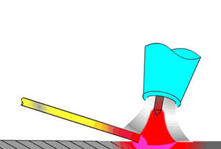
In carbon dioxide welding, the welding wire deposits onto the workpiece (weld) in two forms:
- Short circuit transition
- Fine drop transition.
The short circuit transition frequency is generally around 100 times/second, and the fine drop transition frequency is higher.
The welding wire serves as an electrode (referred to as point A), while the workpiece is the other electrode (point B).
When the arc is ignited, the welding arc is a part of RH, and the droplet transfer of the welding wire is another part of RH.
For short circuit transition, the wire feeding speed influences the frequency of short circuit transition. The faster the wire feeding speed, the higher the frequency of short circuit transition, which increases the opportunities to provide a path for this circuit in a unit time. As a result, the equivalent resistance RH becomes smaller, and the current also increases.
Moreover, carbon dioxide welding uses a thin welding wire with high current density, matched with a flat characteristic power supply. Arc self-regulation plays an essential role in the welding process.
During the welding wire feeding process, the flat characteristic power supply increases the welding wire’s melting speed, allowing for adjusting the welding current by modifying the wire feeding speed locally.
In summary, the welding current in carbon dioxide welding is the outcome of the collective influence of E, R, and RH.
However, in this system, E and R have a relatively wide range of adaptation, while RH is more sensitive to changes in the system.
To maintain welding process stability and reduce spatter, it’s necessary to frequently adjust the wire feeding speed so that the welding wire melting speed matches the wire feeding speed.
This process results in changes to the welding current, which is why we habitually refer to adjusting the wire feeding speed as adjusting the welding current.
If we think that wire feeding speed is the only way to adjust welding current, we may increase the wire feeding speed blindly to increase the welding current, which can cause “wire jacking” – a phenomenon where the welding gun is pushed back and the welding process becomes discontinuous.
In contrast, reducing the wire feeding speed only to decrease current can cause a discontinuous welding process with large splashes, resulting in weak welding gun and high-stacked but unpenetrated weld seams.
To achieve optimal welding results, experienced welders coordinate voltage and current (wire feeding speed) adjustments while observing the weld state and listening to the sound of wire transition.
Beginners can refer to the CO2 welding arc characteristic curve formula to adjust, where UH=15+0.04I (UH represents the arc voltage; I represents the welding current).
For instance, when the welding current is 200A, the arc voltage should be around 23V. These two data can be read from the voltmeter and ammeter on the power supply.
It’s worth noting that due to the voltage drop of the welding cable and contact resistance of each connection point in the welding circuit, the voltmeter reading might be higher than actual voltage.
When using a certain diameter of welding wire, there’s more than one stable working point in the welding process. For example, when using φ1.2mm welding wire in a short-circuit transition state, the current can be adjusted from 90A to 150A, and the voltage range is between 19V and 23V. In the particle transition state, the current can range from 160A to 400A, and the voltage can be adjusted to work between 25V and 38V.