CO2 Gas Shielded Welding: Ideal Current and Voltage Control
How do you get the perfect weld? Understanding the intricacies of adjusting welding machine current and voltage is crucial. This article explores the key factors influencing the ideal settings for CO2 gas shielded welding, including the relationship between welding current, voltage, and wire feeding speed. By mastering these elements, you can achieve a stable arc length and superior welding quality. Dive in to learn how to optimize your welding machine settings for the best results.
CO2 gas shielded welding involves melting the welding wire using welding voltage as the energy source.
The welding wire melts at a faster rate as the voltage is increased.
The welding current is determined by balancing the wire feeding speed with the melting speed.
1. Welding current
The selection of welding current should be based on various welding conditions such as plate thickness, welding position, welding speed, material, and other relevant parameters.
For carbon dioxide gas shielded welding, it is crucial to ensure that the welding current matches the welding voltage, and that the wire feeding speed and welding voltage are consistent with the melting capacity of the welding wire. This is necessary to maintain the stability of the arc length during the welding process.
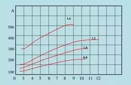
Relationship between welding current and wire feeding speed
For a given welding wire, increasing the cable size results in a higher wire feeding speed.
Similarly, when the current remains constant, using a thinner welding wire will result in a faster wire feeding speed.
2. Welding voltage
Welding voltage, also known as arc voltage, is responsible for providing the necessary welding energy.
A higher arc voltage translates to greater welding energy, faster melting of the welding wire, and increased welding current.
Arc voltage can be calculated by subtracting the loss voltage of the welding circuit from the output voltage of the welder. This can be expressed using the following formula:
Uarc = Uoutput – Uloss
Assuming that the welding machine has been installed in compliance with the installation requirements, any voltage loss is primarily due to cable extension.
In situations where welding cables need to be extended, the output voltage of the welding machine can be adjusted according to the table below:
Welding current Cable length
100A
200A
300A
400A
500A
10m
About 1V
About 1.5V
About 1V
About 1.5V
About 2V
15m
About 1V
About 2.5V
About 2V
About 2.5V
About 3V
20m
About 1.5V
About 3V
About 2.5V
About 3V
About 4V
25m
About 2V
About 4V
About 3V
About 4V
About 5V
3. Setting of welding voltage
Choose the appropriate welding current based on the plate thickness and welding conditions, and then calculate the welding voltage using the following formula:
< 300A: welding voltage=(0.05 × Welding current+14 ± 2) V
> 300A: welding voltage=(0.05 × Welding current+14 ± 3) V
Example 1: If the welding current is 200A, the welding voltage is calculated as follows:
Welding voltage=(0.05 × 200+14 ± 2)
=(10+14 ± 2) V
=(24 ± 2) V
Example 2: If the welding current 400A is selected, the welding voltage is calculated as follows:
Welding voltage=(0.05 × 400+14 ± 3)
=(20+14 ± 3) V
=(34 ± 3) V
4. Influence of welding voltage on welding effect
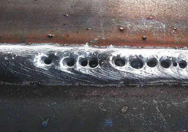
When the voltage is too high, the arc length increases, leading to larger spatter particles that can easily produce pores. Additionally, the weld bead becomes wider, while the solution depth and surplus height become smaller. This can also result in a “patter! patter!” sound.
Conversely, when the voltage is too low, the spatter increases as the welding wire is inserted into the base metal. Furthermore, the weld bead narrows, and both the solution depth and surplus height increase. This can lead to a “bang! bang! bang!” sound.
As the founder of MachineMFG, I have dedicated over a decade of my career to the metalworking industry. My extensive experience has allowed me to become an expert in the fields of sheet metal fabrication, machining, mechanical engineering, and machine tools for metals. I am constantly thinking, reading, and writing about these subjects, constantly striving to stay at the forefront of my field. Let my knowledge and expertise be an asset to your business.
Why does CO2 gas-shielded welding often result in porosity, and how can it be prevented? This article delves into the root causes of these pesky weld defects, explaining how improper…
Which welding technique truly stands the test of time: manual arc welding or CO2 gas shielded welding? This article explores the key differences, advantages, and drawbacks of these two popular…
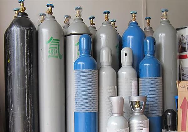
Imagine welding without gas – chaotic and weak. Welding gas is the silent champion, essential for shielding welds from contaminants, stabilizing the arc, and ensuring strong joints. This article explores…
Is your welding machine experiencing gas flow blockages? This common issue can severely impact welding quality, causing defects like porosity and cracks. In this article, we'll explore the primary causes…
Why is choosing the right mixed gas crucial for welding success? This article explores how selecting the appropriate gas mixture can dramatically improve welding quality by refining droplets, reducing splatter,…
Have you ever wondered what makes welding gases so essential yet complex? This article explores the diverse types of welding gases, their roles in protecting and stabilizing welds, and the…
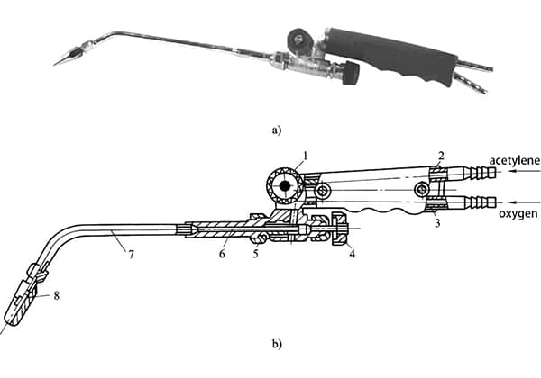
Have you ever wondered how gas welding works and why it's so crucial in mechanical engineering? This article breaks down the principles, types of gas flames, and materials used in…
What if you could enhance your welding precision with just a few adjustments? This article delves into the crucial relationship between welding current, wire diameter, and plate thickness in CO2,…
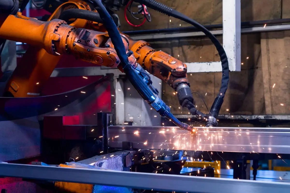
The application of welding robots not only combines the advantages of high and stable efficiency, but also possesses excellent flexibility, ensuring stable operations even in complex environments. A complete welding…