MIG/MAG Welding: Everything You Need to Know
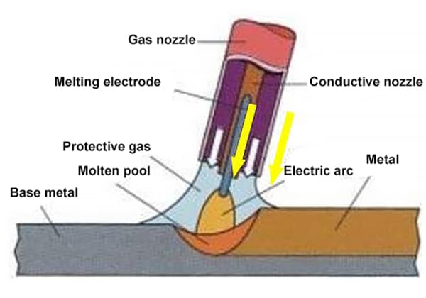
Imagine welding two metals seamlessly while achieving high efficiency and minimal waste. This is the magic of MIG/MAG welding, a technique that combines advanced shielding gases with precise arc control…
What if you could enhance your welding precision with just a few adjustments? This article delves into the crucial relationship between welding current, wire diameter, and plate thickness in CO2, MAG, and MIG welding. You’ll learn how to select the right settings to ensure strong, high-quality welds across different materials and thicknesses. Dive in to uncover tips and techniques that will elevate your welding projects to new levels of accuracy and efficiency.
1. The relationship between the commonly used steel manual arc welding current and the diameter of the welding rod, and the applicable range of plate thickness.
| Types of Steel | Types of Welding Rods | Welding Rod Model | Diameter of the welding rod | Types of Power Supply Polarity | ||||
| φ2.5 | φ3.2 | φ4 | φ5 | φ6 | ||||
| Carbon Steel Low Alloy Steel (20#、35#) (16Mn、15MnV) | Acid Welding Rods | E4303(J422) E5003(J502) | 30-70A | 60-140A | 80-220A | 140-260A | 180-320A | Dual-use for AC and DC |
| Alkali Welding Rods | E5015(J507) E5515(J557) | 30-60A | 50-120A | 80-180A | 120-220A | 160-260A | Direct Current Reversal | |
| Applicable Plate Thickness | (mm) | 2~6 | 4~12 | 6~200 | 10~200 | 20~200 | ||
| Carbon Steel General Low Carbon Steel Large Diameter Pipe (Vertical Down Welding) | Cellulose | E6010 (Root Welding) | 40-120A | 50-140A | 90-200A | 120-250A | Direct Current Connection | |
| Cellulose | E8010 E8518-G | 60-140A | 80-200A | 100-240A | 140-280A | Direct Current Reversal | ||
| Applicable Wall Thickness | (mm) | 4~6 | 6~18 | 8~22 | 8~30 | |||
| Austenitic Stainless Steel (0Cr18Ni9) | Acid Welding Rods | Austenite 102 Austenite 312 | 25-65A | 40-120A | 70-140A | 90-180A | Direct Current Reversal | |
| Alkali Welding Rods | Austenite 137 Austenite 317 | 25-55A | 40-110A | 70-120A | 90-150A | Direct Current Reversal | ||
| Applicable Plate Thickness | (mm) | 2~6 | 4~10 | 6~40 | 10~60 | |||
| Copper & Copper Alloys (Pure Copper) | Alkali Welding Rods | T107 | 80-140A | 100-180A | Direct Current Reversal | |||
| Applicable Plate Thickness | (mm) | 4~10 | 6~20 | |||||
Instruction:
2. The relationship between the commonly used carbon arc gouging current and the carbon rod, as well as the applicable range for plate thickness.
| Type of Carbon Rod | Round Bar | Diameter of the Carbon Rod | φ (mm) | φ3 | φ4 | φ5 | φ6 | φ7 | φ8 | φ9 | φ10 |
| Applicable Current | (A) | 150-180 | 150-200 | 250-250 | 180-300 | 200-350 | 250-400 | 350-450 | 350-500 | ||
| Applicable Plate Thickness | (mm) | 4~6 | 4–8 | 4~10 | 5~10 | 6~12 | 8~20 | 10~30 | 12~50 | ||
| Flat Bar | Specifications | (mm) | 3×12 | 4×8 | 4×12 | 5×10 | 5×12 | 5×15 | 5×18 | 5×20 | |
| Applicable Current | (A) | 180-220 | 200-260 | 220-280 | 240-300 | 250-380 | 280-450 | 300-500 | 350-600 | ||
| Applicable Plate Thickness | (mm) | 4~8 | 6~10 | 6~12 | 8~12 | 8~16 | 8~20 | 10~30 | ≥20 |
Instruction
3. The relationship between the welding current and tungsten electrode diameter in commonly used material manual tungsten inert gas (TIG) arc welding, and the applicable range of plate thickness.
| Material Category | Power Supply Type of Polarity | Tungsten electrode diameter | φ1.6 | φ2.0 | φ2.5 | φ3.2 | φ4 | φ5 | ||||||
| Current Profile | Constant flow | Pulse | Constant flow | Pulse | Constant flow | Pulse | Constant flow | Pulse | Constant flow | Pulse | Constant flow | Pulse | ||
| Carbon Steel and Low Alloy Steel | Direct Current Connection | Permissible Current (A) | 4-50 | 4-100 | 8-90 | 8-180 | 15-150 | 15-250 | 20-200 | 20-300 | 30-250 | 30-350 | 60-500 | 60-650 |
| Applicable Sheet Thickness(mm) | 0.3-2.5 | 0.3-2.5 | 0.5-4 | 0.5-4 | 1–6 | 1–8 | 2–12 | 2–14 | 4–22 | 4–26 | 6–30 | 6–30 | ||
| Stainless Steel | Direct Current Forward Connection | Permitted Current(A) | 4-50 | 4-100 | 8-90 | 8-180 | 15-150 | 15-250 | 20-200 | 20-300 | 30-250 | 30-350 | 60-500 | 60-650 |
| Applicable Plate Thickness(mm) | 0.3-2 | 0.1-2 | 0.5-3 | 0.3-4 | 1–6 | 0.5-6 | 2–10 | 2–12 | 4–20 | 4–24 | 6–30 | 6–30 | ||
| Aluminum and Aluminum Alloys Magnesium and Magnesium Alloys | Alternating Current | Permissible Current(A) | 20-100 | 10-130 | 50-150 | 30-180 | 50-200 | 50-250 | 80-220 | 80-300 | 120-260 | 120-360 | 180-400 | 180-420 |
| Applicable Sheet Thickness(mm) | 0.5-2 | 0.5-3 | 0.5-4 | 0.5-6 | 2–6 | 2–10 | 4–12 | 4–16 | 6–18 | 6–20 | 8–20 | 8–24 | ||
| Copper and Copper Alloys (Pure Copper) | Direct Current Forward Connection | Permissible Current(A) | 8-90 | 8-180 | 15-150 | 15-250 | 20-220 | 20-320 | 30-280 | 30-380 | 60-500 | 60-650 | ||
| Applicable Sheet Thickness(mm) | 0.3-0.5 | 0.1-0.5 | 0.5-2 | 0.3-2 | 1–3 | 1–4 | 2–4 | 1–5 | 4–20 | 4–20 | ||||
| Titanium and Titanium Alloys | Direct Current Forward Connection | Permissible Current(A) | 4-50 | 4-100 | 8-90 | 8-180 | 15-150 | 15-250 | 20-200 | 20-300 | 30-250 | 30-350 | 60-450 | 60-550 |
| Applicable Sheet Thickness(mm) | 0.5-2 | 0.3-2 | 1–3 | 0.5-4 | 2–4 | 1–4 | 2–6 | 2–8 | 4–20 | 4–22 | 6–30 | 6–30 | ||
Instruction
4. The relationship between CO2/MAG/MIG welding current and wire diameter, as well as the applicable range for sheet thickness.
| Material Category | Type of Gas | Tungsten Electrode Diameter | φ0.8 | φ1.0 | φ1.2 | φ1.6 | ||||
| Droplet transition form | CO2 | MAG | CO2 | MAG | CO2 | MAG | CO2 | MAG | ||
| Carbon Steel Low Alloy Steel | 1. CO2 2. 80%Ar+20%CO2 3. 80%Ar+15%CO2+5%O2 | Welding Current Range (A) | 50-150 | 30-150 | 70-180 | 50-300 | 80-350 | 60-440 | 140-500 | 120-550 |
| Arc Voltage Range (V) | 18-22 | 17-22 | 18-22 | 18-32 | 19-34 | 19-35 | 20-38 | 19-40 | ||
| Applicable Sheet Thickness (mm) | 0.9-4 | 0.4-6 | 2–12 | 2–20 | 2–25 | 20-50 | 4-80 | 4-100 | ||
| Austenitic Stainless Steel | 1. 95%Ar+5%CO2 2. 98%Ar+2%O2 | Welding Current Range (A) | 30-120 | 50-300 | 60-440 | 120-500 | ||||
| Arc Voltage Range (V) | 17-24 | 18-34 | 19-35 | 24-40 | ||||||
| Applicable Plate Thickness (mm) | 0.4-6 | 1–12 | 2–20 | 4-50 | ||||||
| Ar(99.9%) | Welding Current Range (A) | Short circuit | Jetting | Short circuit | Jetting | |||||
| Aluminum and Aluminum Alloys | 100-200 | 220-400 | 140-220 | 240-500 | ||||||
| Arc Voltage Range (V) | 16-22 | 22-34 | 17-22 | 24-36 | ||||||
| Applicable Plate Thickness (mm) | 2–24 | 2–30 | 4-50 | 6-80 | ||||||
Instruction:
5. Recommended Method for Striking an Arc and Adjusting Thrust Current in a Direct Current Arc Welding Machine.
| Welding Machine Model | Type of Welding Rod | Welding current range | Arcing current (Ij) | Thrust Current (Id) | Process Characteristics | Weld seam appearance |
| Ordinary Acidic Welding Rod | I≤50A | 1/3 | 1/3 | Arc initiation is easy, no sticking | Good, aesthetically pleasing. | |
| I>50A | Unadded | Unadded | The arc is gentle and very stable, no sticking, minimal spatter | Aesthetically pleasing, no jagged edges. | ||
| Low Hydrogen Alkaline Welding Rod | I≤70A | 1/2 | 1/3 | Arc initiation is easy, no sticking | Good, aesthetically pleasing. | |
| I>70A | Unadded | Unadded | The arc is gentle, no sticking, minimal spatter | Aesthetically pleasing, no jagged edges. | ||
| AT400 | Cellulose Welding Rod | 20-400A | 1/2 | 1/3-1/2 | Arc initiation is easy, no sticking, no arc interruption, high arc stiffness, high blow force, slight spatter | Good. |
Instruction:
6. The actual load sustainability of various arc welding processes under different operating modes.
| Process Method | Mode of Operation | Welding Operation Methods | Continuous Load Factor |
| Gas Tungsten Arc Welding (CO2/MAG) (MIG) | Semi-automatic Hand Welding | Short weld seams, intermittent operations. | 40% |
| Small batch workpieces, continuous operation. | 60% | ||
| Large-scale, continuous operation of workpieces. | 80% | ||
| Fully Automated | Small batch workpieces, continuous operation. | 80% | |
| Large-scale, continuous operation of workpieces. | 100% | ||
| Non-melting electrode inert gas shielded welding (TIG) | Manual Tungsten Inert Gas Welding | Short weld seam, intermittent operation. | 20% |
| Long welding seams, small batches, continuous operations. | 40% | ||
| Long weld seams, large quantities, continuous operation. | 60% | ||
| Fully Automated | Long weld seam, small batch, continuous operation. | 60% | |
| Long weld seams, large quantities, continuous operation. | 80% | ||
| Manual Arc Welding (SMAW) | Manual Welding | Short weld seams, intermittent operation. | 20% |
| Small batch workpieces, continuous operation. | 40% | ||
| Large-scale, continuous operation of workpieces. | 60% | ||
| Gravity Welding | Small batch workpieces, continuous operation. | 60% | |
| Large-scale, continuous operation of workpieces. | 80% | ||
| Carbon Arc Gouging | Handheld Pneumatic Planer | Short weld seam root cleaning, intermittent operation. | 40% |
| Long weld seam cleaning, continuous operation. | 60% | ||
| Automatic Air Planer | Continuous air planing of long weld groove. | 80% |
Instruction:

As the founder of MachineMFG, I have dedicated over a decade of my career to the metalworking industry. My extensive experience has allowed me to become an expert in the fields of sheet metal fabrication, machining, mechanical engineering, and machine tools for metals. I am constantly thinking, reading, and writing about these subjects, constantly striving to stay at the forefront of my field. Let my knowledge and expertise be an asset to your business.