Preventing Argon Arc Welding Porosity: Causes and Solutions
Why does argon arc welding sometimes produce pores, and how can we fix it? Welding porosity, often caused by impurities, improper gas flow, or incorrect technique, can weaken welds and…
Why does CO2 gas-shielded welding often result in porosity, and how can it be prevented? This article delves into the root causes of these pesky weld defects, explaining how improper current and voltage settings contribute to gas entrapment in weld seams. Readers will learn practical measures for identifying, preventing, and correcting these defects to ensure superior welding quality. Explore effective techniques and preventive strategies to master CO2 gas-shielded welding and produce flawless welds.
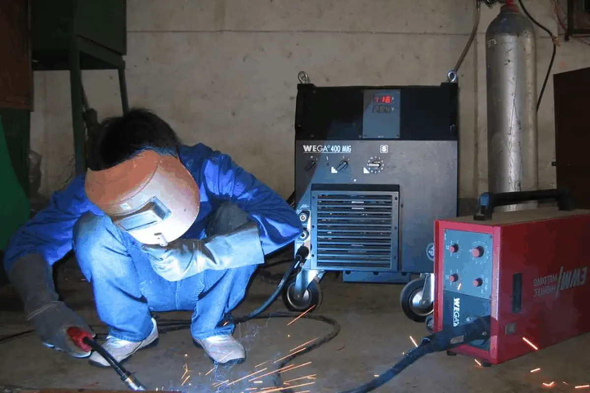
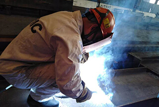
Carbon Dioxide (CO2) gas-shielded welding, a semi-automatic arc welding technique that uses CO2 as a shielding gas and wire as both electrode and filler material, has distinct advantages over manual arc welding, including higher production efficiency, less welding deformation, and superior quality.
It is the preferred method for welders. However, improper selection of current and voltage can lead to weld defects, particularly pores in the weld seam.
Therefore, in daily operations, it is crucial to correctly apply CO2 gas-shielded welding to improve welding quality and promptly re-weld after identifying and removing substandard weld seams with gas defects.
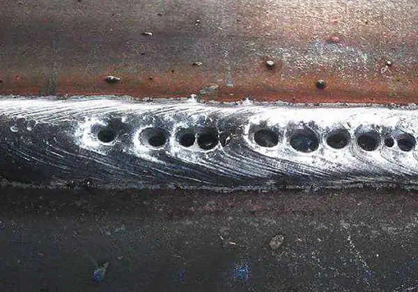
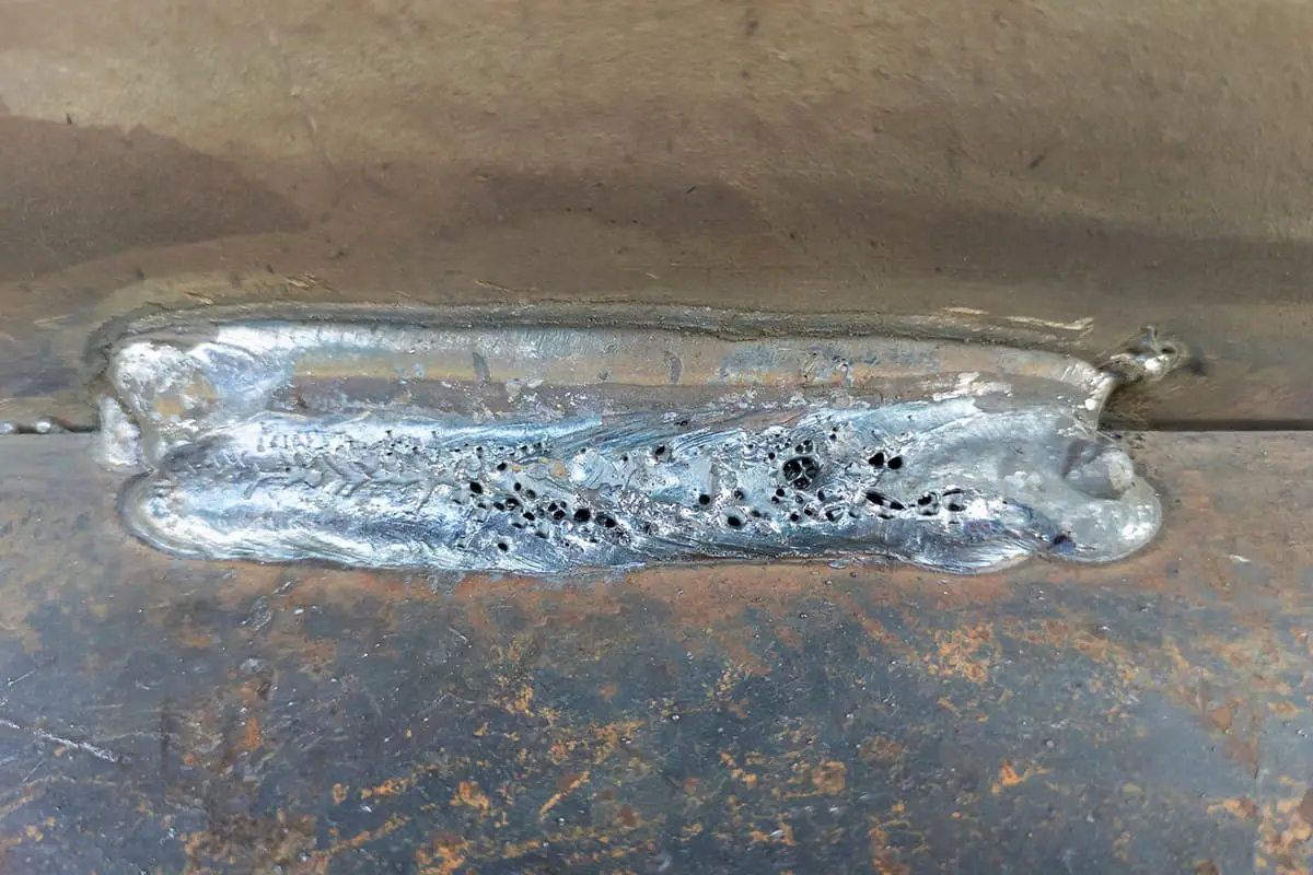
The characteristics of pore distribution are often closely related to their causes and conditions. Depending on their location, some may be on the surface, within the weld seam, or at its root. Some even penetrate the entire weld seam.
From the distribution status, there may be single pores, clusters of multiple pores, or pores that run in a chain-like pattern along the length of the weld seam.
Although different gases form pores that not only have unique appearances and distributions but also vary in their metallurgical and process factors, any gas bubble formed in the molten pool follows the general rule of phase transformation from liquid to gas, involving nucleation and growth stages.
The molten pool absorbs a large amount of gas and reaches a saturated state — under certain conditions, the gas aggregates and forms a nucleus — the bubble nucleus grows into a bubble of a certain size — bubbles rise, get obstructed, and remain in the solidified weld seam, forming a pore.
Therefore, pore formation is a result of several stages: gas absorption by molten metal, bubble nucleation, growth, and emergence. Each stage has its own influencing factors.
The presence of supersaturated gases (or gases that can’t be dissolved) in liquid metal is the material basis for gas nucleation and growth. During welding, the molten pool has adequate conditions to form gas bubbles.
Also, the higher the degree of saturation in the molten pool, the less energy required for the gas to precipitate from the dissolved state.
Two conditions are required for gas growth: first, the internal pressure of the gas must be sufficient to overcome the external pressure it is subjected to.
Second, the growth must be rapid enough to ensure that it reaches a certain macro size before the molten pool solidifies.
Gas rising consists of two processes. First, the bubble must detach from the surface it forms on, and the difficulty of this depends on the contact situation between the bubble and the surface.
The rate of bubble rise is related to the following factors: pore radius, the density of liquid metal, and the viscosity of liquid metal.

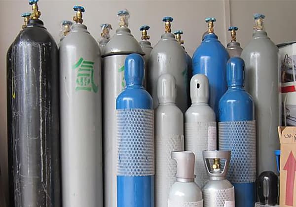
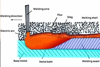
During CO2 gas-shielded welding, due to the absence of slag covering the surface of the molten pool and the cooling effect of the CO2 gas stream, the molten pool solidifies relatively quickly. If the welding material or welding process is not handled properly, CO pores, nitrogen pores, and hydrogen pores may occur.
CO is mainly the product of the reaction between FeO, O2 or other oxides, and carbon (C).
For example, C+O=CO, FeO+C=CO+Fe, MnO+C=CO+Mn, SiO2+2C=2CO+SiO. During the CO2 welding process, when there is a lack of deoxidizing elements in the welding wire metal, more gas will dissolve into the metal in the molten pool, and the C in the molten pool will react with FeO to form CO gas.
When the molten pool metal solidifies too quickly, the generated CO gas doesn’t have enough time to escape, thereby forming CO pores. These pores often appear at the root of the weld or near the surface and are usually needle-shaped.
To prevent the formation of CO pores, it is necessary to use a welding wire that contains enough deoxidizer and has a low carbon content to inhibit the oxidation reaction between C and FeO. If the carbon content in the parent material is high, welding parameters with a larger line energy should be selected technologically to increase the dwell time of the molten pool and facilitate the escape of CO gas.
If the welding wire contains sufficient deoxidizing elements like Si and Mn, and the carbon content in the wire is limited, the aforementioned reduction reaction can be suppressed, effectively preventing the formation of CO pores. Therefore, as long as the welding wire is selected appropriately, the likelihood of CO pore formation in CO2 arc welding is very small.
The main cause of hydrogen pores is that a large amount of hydrogen dissolves into the molten pool at high temperatures, and it can’t be fully expelled during the crystallization process, remaining in the weld metal and forming pores.
The source of hydrogen is the oil contamination and rust on the workpiece and welding wire surfaces, as well as the moisture in the CO2 gas. Oil contamination is hydrocarbons, and rust is ferric oxide containing crystalline water. Both can decompose hydrogen under high temperatures of the electric arc.
Hydrogen in the arc can further ionize, then easily dissolve into the molten pool in an ionized state. During the crystallization of the molten pool, due to the sharp drop in the solubility of hydrogen, the precipitated hydrogen, if not expelled from the molten pool, forms spherical pores in the weld metal.
To avoid H2 pores, the source of hydrogen must be eliminated. Before welding, remove rust, oil contamination, and other impurities from the workpiece and welding wire. More importantly, pay attention to the moisture content in the CO2 gas, as it often is the main cause of hydrogen pores.
CO2 gas has oxidizing properties that can suppress the formation of hydrogen pores. As long as the CO2 gas is dried before welding to remove moisture and the impurities on the surface of the welding wire and workpiece are cleared, the possibility of forming hydrogen pores is very small. Therefore, CO2 arc welding is a recognized low-hydrogen welding method.
Under high arc temperatures, molten pool metal has a high solubility for nitrogen. However, when the temperature of the molten pool drops, the solubility of nitrogen in liquid metal decreases rapidly, precipitating a large amount of nitrogen. If it cannot escape from the molten pool, nitrogen pores are formed.
Nitrogen pores often appear near the surface of the weld and are distributed in a honeycomb pattern. In severe cases, small pores can be widely distributed throughout the weld metal. These tiny pores can often be found in metallographic inspections, or they can be enlarged into permeability defects in hydraulic tests and revealed.
The main reason for nitrogen pore formation is the destruction of the protective gas layer, which allows a large amount of air to invade the welding area.
Factors causing the destruction of the protective gas layer include:
To avoid nitrogen pores, the gas protection effect must be improved. You should choose a CO2 gas with qualified purity, use appropriate gas flow parameters during welding; check if there is a gas leak or blockage from the gas cylinder to the welding torch; and increase the wind protection measures for outdoor welding.
In addition, in field construction, it is best to choose a welding wire containing nitrogen-fixing elements (such as Ti, Al).
In CO2 gas shielded welding, intense oxidation-reduction chemical reactions occur, leading to substantial spattering and heat loss. If any step is not well-controlled, gas pores might easily form. The main reasons for gas pore formation are as follows:

Gas pores as a type of defect in the weld seam mainly pose the following dangers: they can lead to the formation of cold cracks, fatigue cracks, delayed cracks, and other secondary defects in the pore areas. These defects can weaken the yield strength and tensile strength of the weld seam.
In response to the above situation, operators are required to choose the correct welding process parameters during remedial welding. In addition, they should maintain a certain dry extension length of the nozzle and pay attention to the angle of the welding torch. The specifics are as follows:
7.7.1 Welding current and arc voltage
The arc voltage is a critical parameter in welding; its magnitude determines the length of the arc and the transition form of the droplet, and has a significant impact on spatter.
Under a certain diameter of welding wire and welding current, if the arc voltage is too high, the melting speed of the welding wire increases, the arc lengthens, and the droplet cannot transition normally, leading to large particles flying out and increased spatter.
If the arc voltage is too low, it is difficult to ignite the arc, the melting speed of the welding wire decreases, the arc shortens, and the welding wire plunges into the molten pool, which also causes large spatter and poor weld seam formation.
When the welding current and arc voltage are optimally matched, the frequency of droplet transition is high, spatter is minimized, and the weld seam formation is beautiful.
Table 1 shows the typical short-circuit transition welding process parameters for three different diameter welding wires, where welding spatter is minimized.
Table 1: Short-circuit transition welding process parameters for different diameter welding wires
| Welding wire dia. (mm) | Arc voltage (V) | Welding Current (A) |
| 0.8 | 18 | 100~110 |
| 1.2 | 19 | 120~135 |
| 1.6 | 20 | 140~180 |
7.7.2 Welding Torch Angle
Generally, the angle between the welding torch and the plane of the weld should be maintained at about 65°. The welding operation should be steady, with the torch neither moving too high nor too low, or too fast or too slow.
If the welding site is exposed to strong wind, a thin steel plate can be used to block the wind. It is best to use a 2mm thick, 200mm wide thin steel plate bent into a U-shaped frame and placed next to the welding area.
The U-shaped frame can block wind coming from several directions to avoid interference with the welding area, and can also prevent arc light from harming the eyes of surrounding workers.
The angle between the welding torch and the base material should be maintained within a 45° range. The running speed during horizontal welding should not be too fast, and the swing amplitude of the welding torch should not be too large, generally between 10~15mm.
If there is a lot of wind, a steel plate or a U-shaped frame made of steel can be placed next to the welding area to block the wind. However, the placement of the steel plate should not obstruct the welder’s own line of sight or interfere with the swing of the welding torch.
The angle between the welding torch and the weld seam of the base material should be about 15°. The welding current should not be too large, generally about 20% less than flat welding.
During vertical welding, due to the influence of the rising airflow from below the welding area, the CO2 flow rate can be slightly increased during the welding operation (depending on the situation).
The higher the position of vertical welding is from the ground, the greater the rising airflow. If this situation is encountered, a 200mm thin steel plate can be placed underneath the welding torch to effectively block the impact of the rising airflow on the welding area.
Due to long-term welding, spatter can block the nozzle of the welding torch, reducing the flow of CO2 gas and impairing the protective performance, which can easily lead to the formation of nitrogen pores.
Spatter should be removed promptly in this situation. Over time, the nozzle can become deformed and narrowed with use, reducing the protective range and making gas pores more likely.
When this situation is encountered, a new nozzle should be installed before welding operations can continue.
When all welding operations are complete, the welder should switch off the welding machine and CO2 valve to prevent overheating and potential damage to the heating wire.
The main reasons for the formation of pores in CO2 gas shielded welding are the cleanliness of the welding surface of the base material (presence of oil, oxides), insufficient CO2 gas flow to protect the welding area, excess moisture in the gas affecting its purity; too large a distance between the nozzle and the workpiece allowing air intrusion; too much spatter adhering to the inner wall of the nozzle affecting the protection effect; and wind at the operation site disrupting the protective gas curtain.
In addition to choosing the correct welding process parameters and ensuring the good condition of the welding equipment, corrective measures should also include ensuring the quality of the welding wire and the purity of the CO2 gas, and choosing the correct welding angle, among other things.

As the founder of MachineMFG, I have dedicated over a decade of my career to the metalworking industry. My extensive experience has allowed me to become an expert in the fields of sheet metal fabrication, machining, mechanical engineering, and machine tools for metals. I am constantly thinking, reading, and writing about these subjects, constantly striving to stay at the forefront of my field. Let my knowledge and expertise be an asset to your business.