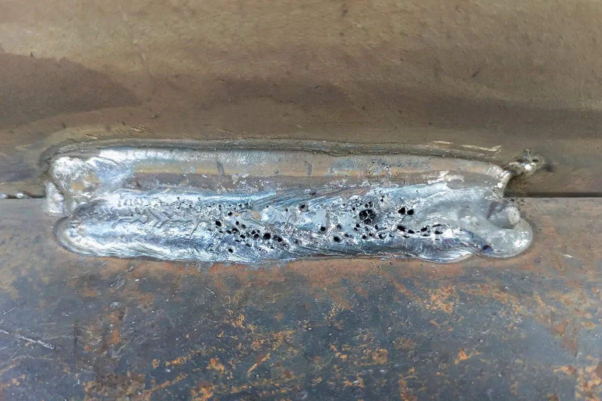
Preventing Argon Arc Welding Porosity: Causes and Solutions
Why does argon arc welding sometimes produce pores, and how can we fix it? Welding porosity, often caused by impurities, improper gas flow, or incorrect technique, can weaken welds and…
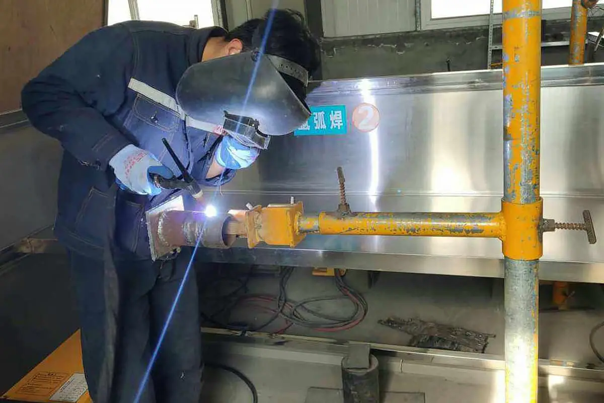
Have you ever wondered how professionals create precise cuts in thick metal without resorting to traditional methods? Carbon arc gouging might be the answer you’re looking for. This process, using an electrical arc and compressed air, efficiently removes metal, allowing for precise repairs and modifications. In this article, you’ll discover the principles behind carbon arc gouging, its applications, the necessary equipment, and safety tips to ensure successful implementation. Dive in to learn how this technique could enhance your metalworking projects.
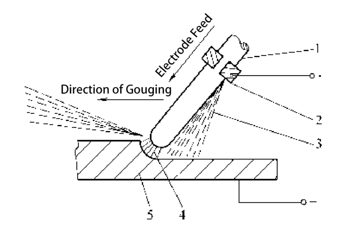
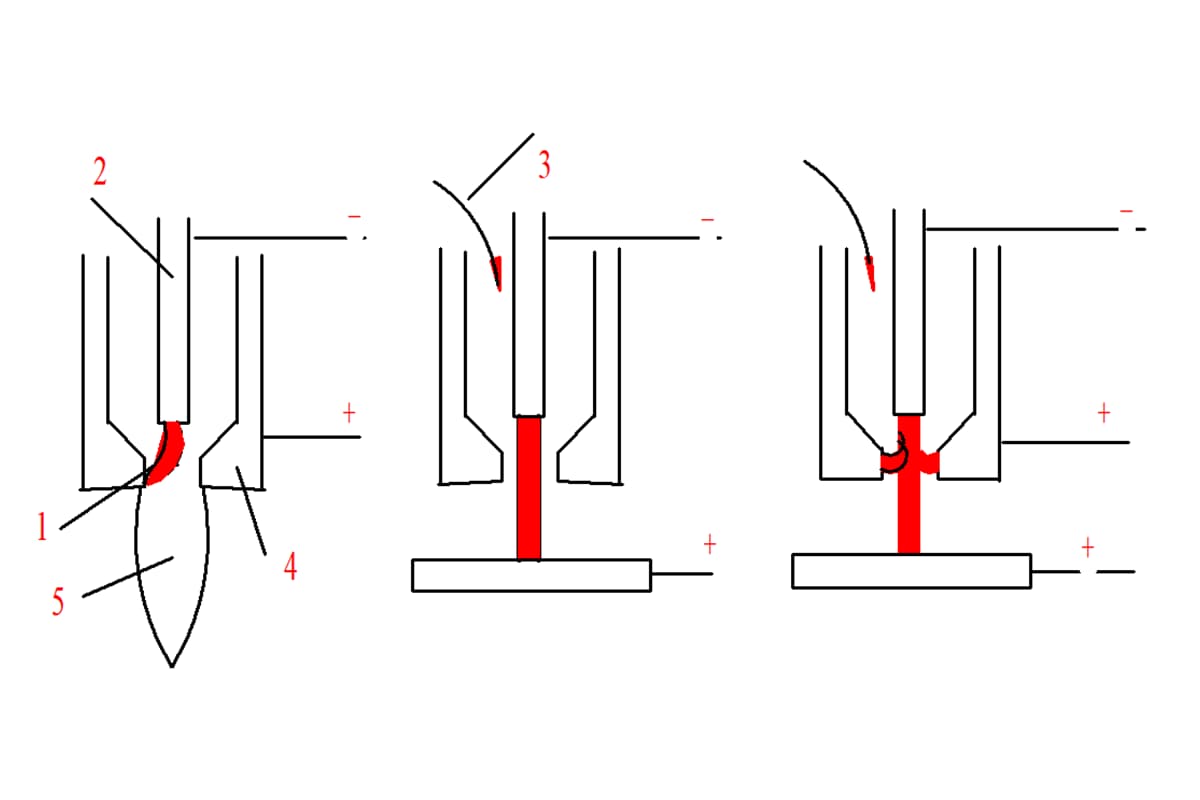
Carbon arc gouging relies on the high temperature generated by an electrical arc between a carbon rod and a metal workpiece to locally melt the metal. Compressed air flow is then used to blow away the molten metal, allowing for the creation of gouges in the workpiece. This process is depicted in Figure 8-1.
1 – Carbon Rod
2 – Carbon Arc Gouging Clamp
3 – Compressed Air
4 – Electric Arc
5 – Workpiece
1) It does not require a large operating space, offering a high degree of flexibility and the ability to work in all positions.
2) It allows for a clear view of defect shapes and depths, thus enhancing the pass rate of welder repairs.
3) Carbon Arc Gouging has low noise levels, high efficiency, and low labor intensity, with simple equipment required.
4) It can cut through metal materials that are difficult to sever with an oxyacetylene flame.
5) Drawbacks of Carbon Arc Gouging include substantial smoke, dust pollution, and intense arc light radiation. It also requires a high-power DC power source, which can be costly, and demands a high level of operational skill.
1) It is primarily used for double-sided welding of low carbon steel, low alloy steel, and stainless steel materials, for root removal.
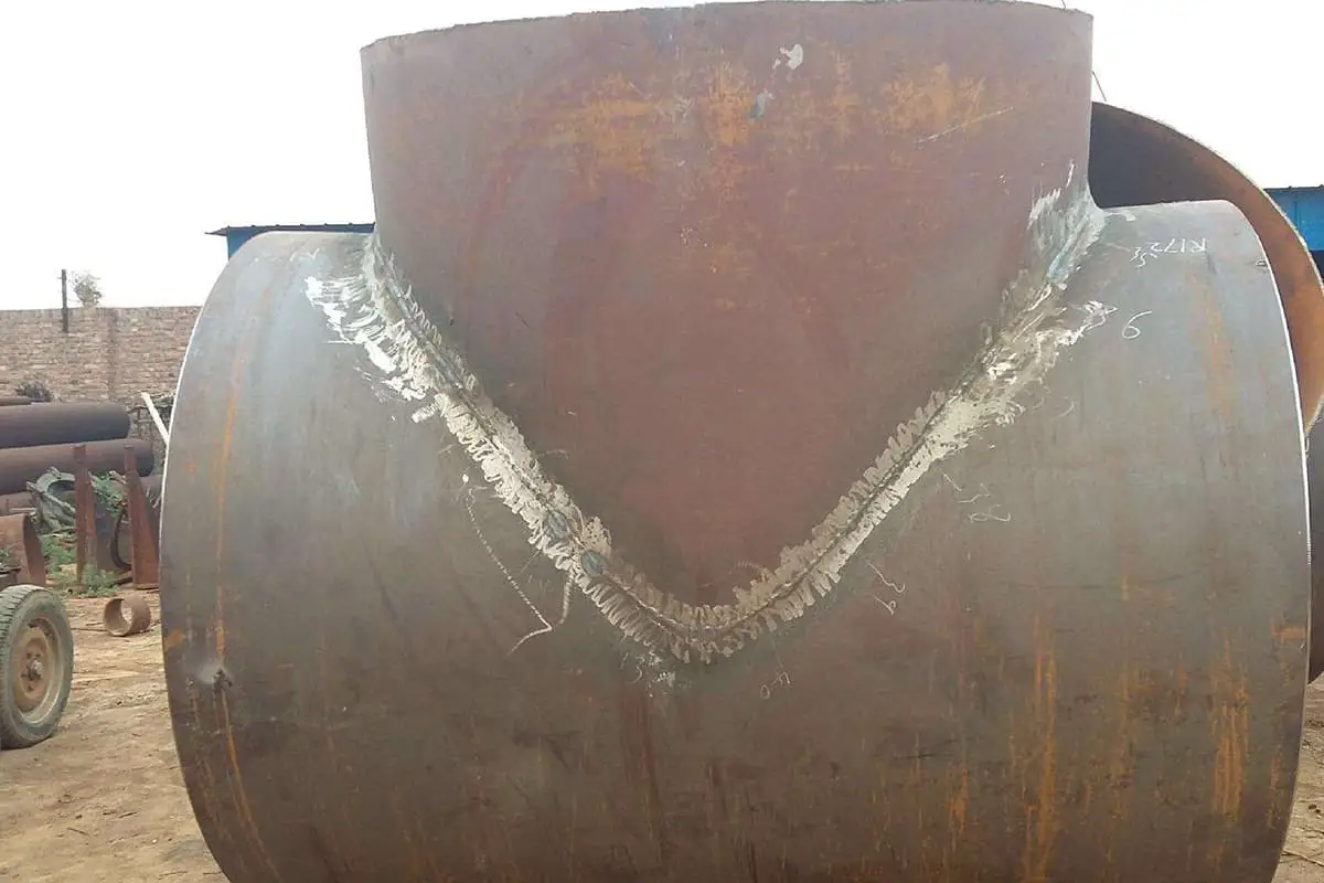
2) For important metal structures, atmospheric vessels, and pressure vessels, where there are unacceptable weld defects exceeding the standard, the carbon arc gouging process can be used to remove these defects before repair.
3) Manual carbon arc gouging is commonly used to prepare bevels for small parts, single parts, or irregular welds, particularly the U-shaped bevels, which underscores the advantages of this process.
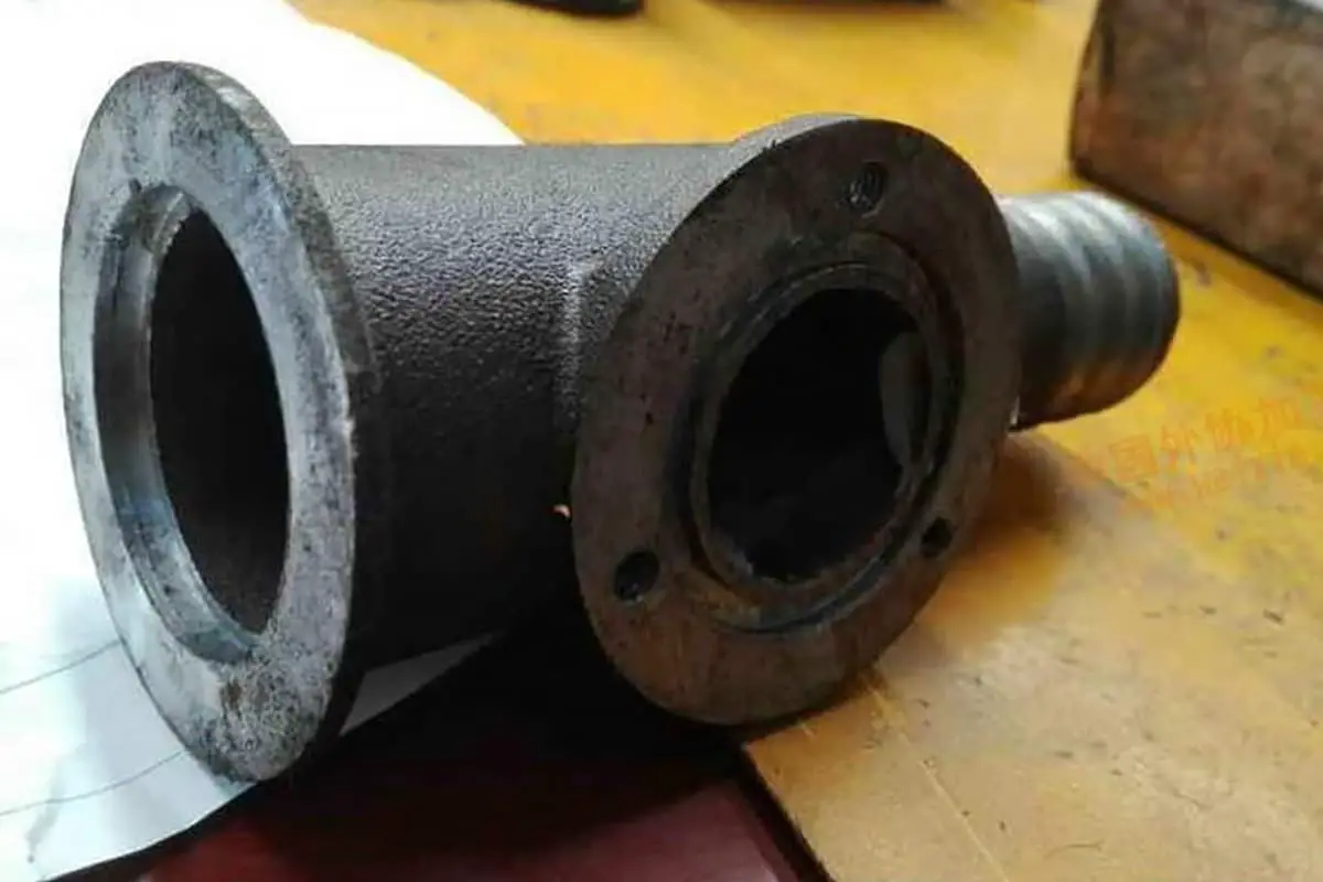
4) It is used to remove casting flash, burrs, gating systems, risers and surface defects of castings.
5) It is used for cutting high alloy steel, copper, aluminum, and their alloys.
Carbon arc gouging should not be used on low alloy steel plates that are sensitive to cold cracking.
The main equipment for carbon arc gouging includes a power source and a compressed air source.
1. Requirements for Carbon Arc Gouging Pliers
Carbon arc gouging pliers must meet the following three basic requirements.
(1) The carbon rod must be securely held, and it should be easy to replace.
(2) The pliers should have good electrical conductivity and accurately deliver compressed air.
(3) The design should be compact and easy to operate.
2. Types of Carbon Arc Gouging Torches and Their Pros and Cons
Drawback: It can only plane in a single direction, either to the left or to the right.
Advantage of the circumferential air supply air planing clamp: The nozzle is insulated from the workpiece, with compressed air sprayed from around the carbon rod, allowing for uniform cooling, and it’s suitable for operations in all directions.
Disadvantage: It has a complex structure, and the screw that secures the carbon rod can easily short-circuit with the workpiece.
The new side air supply carbon arc air planing clamp is shown in Figure 8-3.
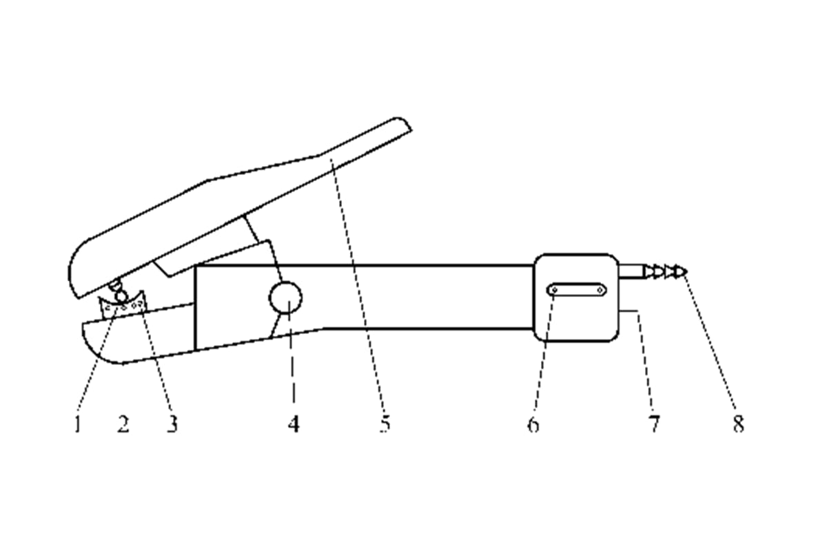
1 – Carbon Rod
2 – Air Hole
3 – Adjustable Angle Pliers Mouth (Conductive Nozzle)
4 – Air Switch
5 – Clamp Handle
6 – Cable Fastening Screw
7 – Cable Interface
8 – Compressed Air Connector
3. Combined Electric-Air Hose
The new Combined Electric-Air Hose is shown in Figure 8-4.
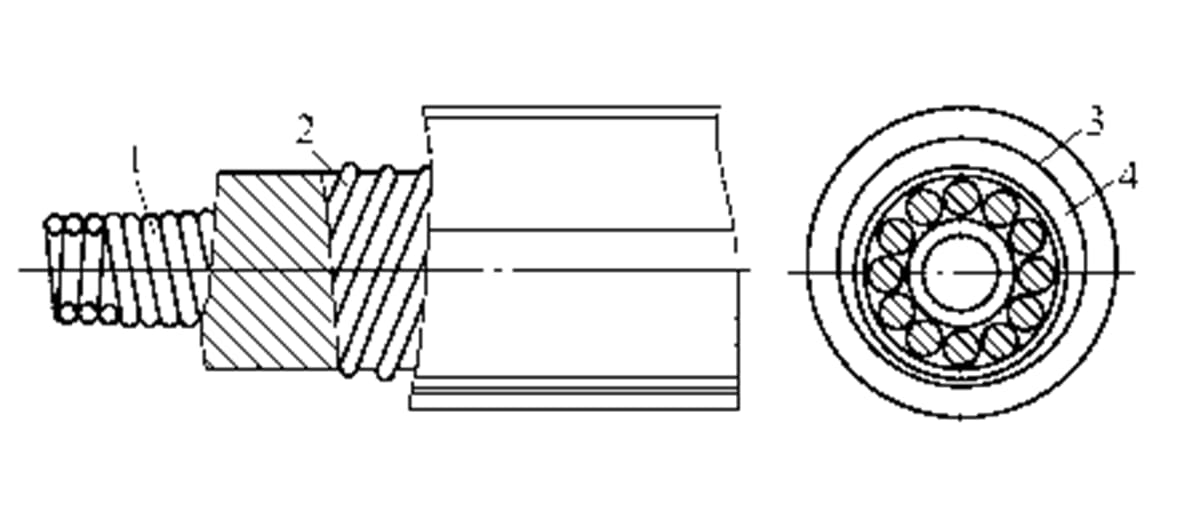
1 – Spring Tube
2 – External Additional Steel Wire
3 – Clamping Rubber Tube
4 – Multi-strand Conductor
The carbon rod is the primary consumable material in carbon arc gouging operations. It serves the purpose of conducting electricity and igniting the arc.
The most commonly used type is the copper-coated solid carbon rod.
There are two forms of carbon rods: round and flat. Round carbon rods are mainly used for cleaning welding roots on the back of weld seams or for defect removal during weld repair. Flat carbon rods, with their wider gouge, can be used for beveling or cutting cast iron, alloy steel, and non-ferrous metals.
The requirements for carbon rods are:
1. Good electrical conductivity
2. High-temperature resistance
3. The carbon rod should have a certain degree of strength.
The process parameters for carbon arc gouging include power source polarity, carbon rod diameter and current, carbon rod diameter and plate thickness, carbon rod protrusion length, carbon rod tilt angle, compressed air pressure, arc length, and gouging speed.
1. Power Source Polarity
For carbon arc gouging of low carbon steel, low alloy steel, and stainless steel, direct current reverse polarity is used.
2. Carbon Rod Diameter and Current
3. Carbon Rod Diameter and Plate Thickness
The relationship between the diameter of the carbon rod and the thickness of the plate is shown in Table 8-3.
Relationship between carbon rod diameter and plate thickness (unit: mm)
| Steel plate thickness | Carbon rod diameter | Steel plate thickness | Carbon rod diameter |
| 3 | 8-12 | 6-7 | |
| 4-6 | 4 | >10 | 7-10 |
| 6-8 | 5-6 | >15 | 10 |
Ideally, the diameter of the carbon rod should be 2-4mm smaller than the required width of the groove.
4. Length of Carbon Rod Extension
The length of the carbon rod extension refers to the distance from the conductive nozzle to the endpoint of the carbon rod, as shown in Figure 8-6. The typical extension length ranges from 80 to 100mm.

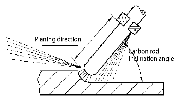
5. Carbon Rod Inclination Angle
The angle between the carbon rod and the workpiece along the direction of the carbon arc air gouging is referred to as the carbon rod inclination angle. Generally, a manual carbon arc air gouging utilizes an inclination angle of approximately 25° to 45°. The carbon rod inclination angle is illustrated in Figure 8-7.
6. Compressed Air Pressure
The required pressure for compressed air typically ranges from 0.4 to 0.6 MPa.
7. Arc Length
During operation, it is advisable to use a short arc with a typical length of about 1 to 2 mm.
8. Planing Speed
A planing speed of approximately 0.5 to 1.2 m/min is generally considered appropriate.
1. Basic Operations
(1) Preparations before gouging
(2) Striking the arc
(3) Gouging
2. Beveling
Firstly, the width of the U-shaped groove should be chosen based on the thickness of the plate, then determine the diameter of the carbon rod and gouging current.
Note that the centerline of the carbon rod should coincide with the centerline of the bevel. If these two centerlines do not coincide, the shape of the gouged bevel will be asymmetrical.
3. Weld Root Removal
Welders should select suitable process parameters according to different materials and thicknesses. It should be noted that the inner weld seam should generally be welded first to avoid the need to use carbon arc gouging to remove the inner weld root.
When removing the outer weld root, the melted metal is always blown downwards. When removing the weld root on thicker plates, multiple gouging passes may be required to meet the requirements.
4. Gouging Weld Defects
When gouging out weld defects, the gouging current used should be slightly lower. During the gouging process, when the defect becomes visible, it should be lightly gouged again until all defects are completely removed.
1. Carbon Inclusion
2. Slag Inclusion
3. Copper Spots
4. Irregular Gouge Size and Shape
After low carbon steel is processed with carbon arc gouging, it does not affect its weldability.
For steel types with a yield point between 450 and 600 MPa, and those with considerable thickness or structural rigidity, preheating is required before carbon arc gouging. The preheat temperature should be equal to or slightly higher than the preheating temperature during welding.
The uniqueness of carbon arc gouging on stainless steel should be noted. Avoid damaging the medium contact surface with the spatter from carbon arc gouging. Make sure the carbon arc gouging groove is kept distant from the medium contact surface.
To prevent the impact on the stainless steel’s intergranular corrosion resistance, ultra-low carbon stainless steel, which is in contact with highly corrosive media, should not use carbon arc gouging for root removal. Instead, angular grinding should be adopted.
1) Operators should wear personal protective equipment according to the characteristics and requirements of the work.
2) Check if the welding machine is properly grounded; ensure the insulation at the connection points is good. Inspect if the compressed air pipeline joints are secure.
3) Conduct safety verification of the workpiece being gouged. Closed pipes and containers should not be gouged. Unknown objects should be inspected beforehand and confirmed safe before operation. The work site must be thoroughly inspected; flammable and explosive materials are strictly forbidden within a 10m radius to prevent fire hazards.
4) The airflow direction should not face people during operation. Work outdoors should be carried out downwind. Operation is prohibited in rainy or snowy weather to prevent electric shock.
5) Carbon arc gouging produces considerable dust and smoke. Ventilation should be enhanced at the work site. When operating inside a container, ventilation, smoke and dust removal measures must be implemented. A designated person must supervise the operation to prevent poisoning or suffocation.
6) After work is completed, the power supply should be cut off, the air compressor or air pipeline switch should be closed, the workspace should be cleaned, and only after making sure there are no ignition sources can the operator leave the site.
7) Other safety measures are the same as for general stick arc welding.

As the founder of MachineMFG, I have dedicated over a decade of my career to the metalworking industry. My extensive experience has allowed me to become an expert in the fields of sheet metal fabrication, machining, mechanical engineering, and machine tools for metals. I am constantly thinking, reading, and writing about these subjects, constantly striving to stay at the forefront of my field. Let my knowledge and expertise be an asset to your business.