How does a welding process that combines extreme heat, precision, and efficiency sound? Plasma arc welding, an advanced technique, does exactly that. This method uses a plasma arc to create high-energy, high-temperature welds, suitable for both thin and thick materials. By understanding its principles and applications, you’ll see how this technology can revolutionize industrial welding, offering strong, high-quality joints in a wide range of metals. Discover the intricacies of plasma arc welding and its potential to enhance your welding projects.
1. Characteristics of Plasma Arc and Its Generator
1. Formation of Plasma Arc
A plasma arc is a compressed tungsten electrode argon arc with high energy density, temperature, and arc force. The plasma arc is obtained through three compression effects:
1) Mechanical Compression: The restricted expansion of the arc column’s cross-sectional area, caused by the aperture of the water-cooled copper nozzle, is known as mechanical compression.
2) Thermal Compression: The cooling water in the nozzle forms a layer of cold gas near the inner wall of the nozzle, reducing the effective conductive area of the arc column. This further increases the energy density and temperature of the arc column. This effect, achieved through water cooling to further increase the temperature and energy density of the arc column, is known as thermal compression.
3) Electromagnetic Compression: Due to the aforementioned compression effects, the arc current density increases, and the electromagnetic contraction force generated by the arc current’s own magnetic field becomes stronger. This results in further compression of the arc, known as electromagnetic compression.
2. Classification of Plasma Arc
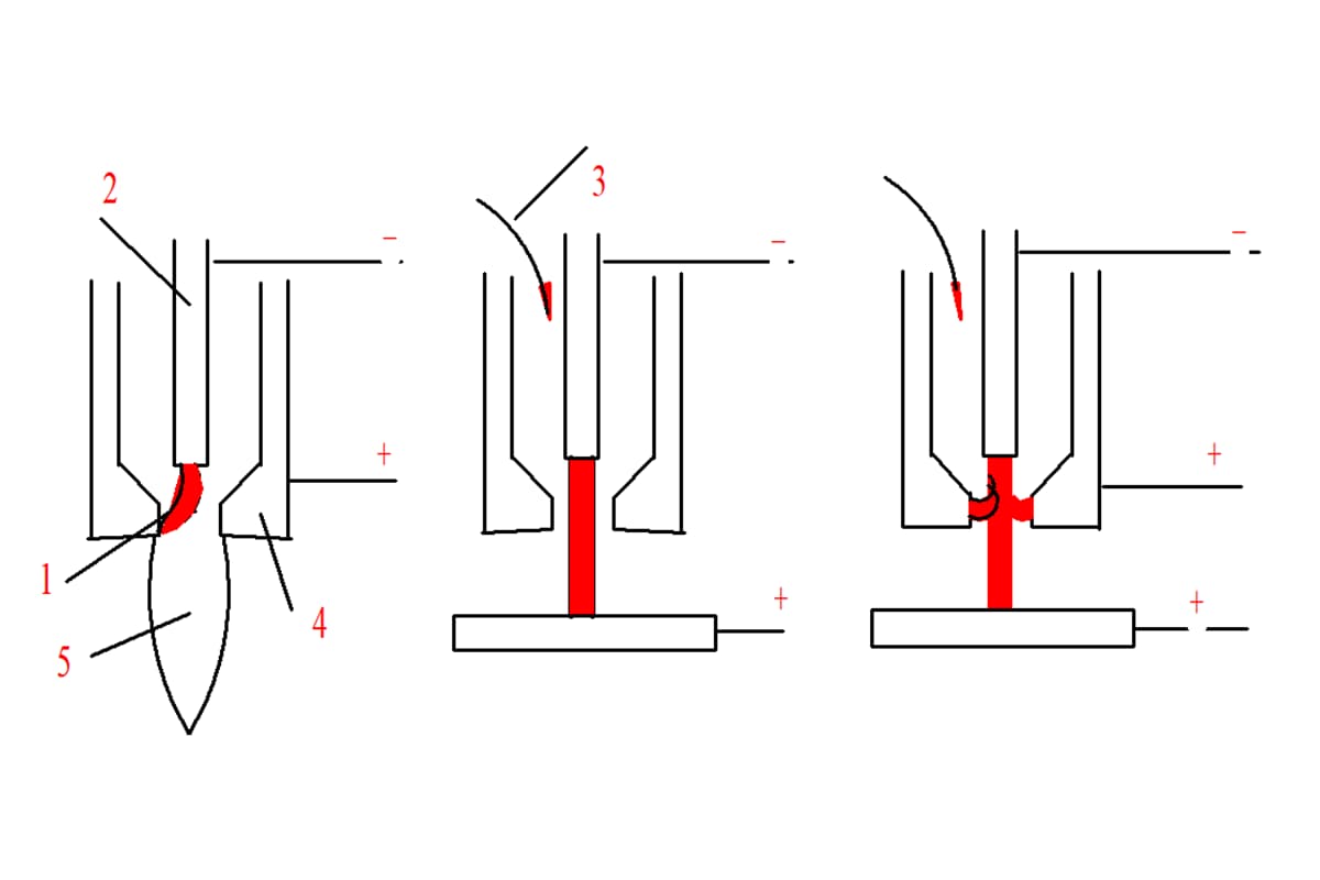
(1) Non-transferred Arc
The non-transferred arc burns between the tungsten electrode and the nozzle. During welding, the positive pole of the power source is connected to the water-cooled copper nozzle, while the negative pole is connected to the tungsten electrode. The workpiece is not connected to the welding circuit. The arc is carried out by the high-speed ejection of plasma gas. This type of arc is suitable for welding or cutting thinner metals and non-metals.
(2) Transferred Arc
The transferred arc burns directly between the tungsten electrode and the workpiece. During welding, the non-transferred arc between the tungsten electrode and the nozzle is first ignited, and then the arc is transferred to the tungsten electrode and the workpiece. The nozzle is not connected to the welding circuit during operation. This type of arc is used for welding thicker metals.
(3) Combined Arc
A combined arc refers to an arc where both the transferred arc and non-transferred arc coexist. The mixed arc can maintain stability at very low currents, making it particularly suitable for welding thin and ultra-thin plates.
Non-transferred Arc Transferred Arc Combined Arc
3. Plasma Arc Characteristics
(1) The arc static characteristic curve of the plasma arc is significantly different from that of the TIG arc:
1.1 The E-value is larger, thus shifting upward. The straight section becomes narrower, and the slope of the rising section increases.
1.2 The descending section of the combined arc is not obvious; therefore, the small current arc is very stable.
(2) The arc temperature is high, ranging from 24000K to 50000K, with a high power density and energy density of 105-106W/cm2. In contrast, the TIG arc has a temperature range of 10000-24000K and a power density less than 104W/cm2.
(3) The rigidity is high, with a large arc concentration factor.
(4) The heat generated by the arc column has a significant effect on heating the workpiece.
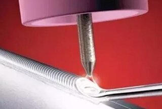
4. Characteristics and Applications of Plasma Arc Welding
(I) Characteristics
Due to its high energy density, temperature, and rigidity, the plasma arc has the following advantages compared to conventional arc welding:
1) Strong penetration ability, capable of welding through stainless steel plates with a thickness of 8-10mm without the need for beveling or filler wire.
2) The quality of the weld seam is not sensitive to changes in arc length. This is because the shape of the arc is close to cylindrical and has good straightness. The variation in arc length has minimal impact on the heating spot area, making it easy to obtain uniform weld seam shapes.
3) The tungsten electrode is recessed inside a water-cooled copper nozzle, avoiding contact with the workpiece and preventing the occurrence of tungsten inclusion in the weld metal.
4) The plasma arc has a high ionization degree, making it stable even at low currents, allowing for the welding of miniature precision parts.
The disadvantages of plasma arc welding are as follows:
2) The welding gun and control circuitry are complex, and the nozzle has a low service life.
3) There are multiple welding parameters, requiring a high level of technical proficiency from the welding operator.
(2) Applications
Plasma arc welding can be used to weld various metals that can be welded with tungsten inert gas (TIG) welding, such as stainless steel, aluminum and aluminum alloys, titanium and titanium alloys, nickel, copper, and Monel alloy. This welding method can be applied in aerospace, aviation, nuclear energy, electronics, shipbuilding, and other industrial sectors.
The main components include the electrode, electrode holder, compressed nozzle, intermediate insulator, upper gun body, lower gun body, and cooling sleeve. The most critical components are the nozzle and electrode.
1. Nozzle
Classification: Based on the number of nozzle holes, there are two types: single-hole and multi-hole.
In multi-hole nozzles, in addition to the main central hole, there are multiple small holes on the left and right sides of the main hole. The plasma gas ejected from these small holes has an additional compressive effect on the plasma arc, causing the cross-section of the plasma arc to become elliptical. When the long axis of the ellipse is parallel to the welding direction, it can significantly increase the welding speed and reduce the width of the heat-affected zone.
The most important nozzle shape parameters are the compression aperture and the length of the compression channel.
1) Nozzle aperture (dn):
The dn determines the diameter and energy density of the plasma arc. A smaller diameter results in greater compression of the arc, but if it is too small, it can lead to decreased stability of the plasma arc, even causing double arcing and nozzle damage. The selection of dn should be based on the welding current, plasma gas type, and flow rate.
2) Nozzle channel length (l0):
Under a certain compression aperture, a longer l0 provides stronger compression of the plasma arc. However, if l0 is too large, the plasma arc becomes unstable. It is usually required that the ratio l0/dn falls within a certain range. For transfer arc, it is generally 1.0-1.2, and for mixed arc, it is 2-6.
3) Conical angle (α):
The conical angle has little impact on the compression of the plasma arc and can range from 30° to 180°. However, it is preferable to match the shape of the electrode tip to ensure stable anchoring of the anode spot at the tip of the electrode. During welding, the angle is generally 60° to 90°.
Types of Nozzles
Nozzle Material:
The nozzle is typically made of copper and is directly water-cooled.
Electrode:
1) Material:
Plasma arc welding commonly uses thoriated tungsten electrodes or ceriated tungsten electrodes. In some cases, zirconiated tungsten electrodes or zirconium electrodes may be used. Tungsten electrodes generally require water cooling. For low current applications, indirect water cooling is used, and the tungsten electrode is in the form of a rod. For high current applications, direct water cooling is used, and the tungsten electrode has an embedded structure.
2) Shape:
The tip of a rod-shaped electrode is usually ground to a sharp cone shape or a conical platform shape. For higher current applications, it can also be ground into a spherical shape to reduce burn-off.
3) Inner Contraction Length and Concentricity:
Unlike TIG welding, in plasma welding, the tungsten electrode is generally contracted inside the compressed nozzle. The distance from the outer surface of the nozzle to the tip of the tungsten electrode is known as the inner contraction length (lg).
To ensure arc stability and prevent double arcing, the tungsten electrode should be concentric with the nozzle, and the inner contraction length (lg) of the tungsten electrode should be appropriate (lg = l0 ± 0.2mm).
3. Gas Delivery Methods:
a) Tangential: This method provides high compression, with low pressure at the center and high pressure at the periphery. It helps to stabilize the arc at the center.
b) Radial: This method provides lower compression compared to the tangential method.
5. Dual Arc and its Prevention Measures
1. Dual Arc
Under normal conditions, a transferred arc is formed between the tungsten electrode and the workpiece.
However, in certain abnormal situations, a parallel arc may occur, known as a dual arc, which burns between the tungsten electrode and the nozzle, as well as between the nozzle and the workpiece.
2. Dual arc generation mechanism
Theory of cold gas film breakdown
3. Causes and prevention measures for dual arc generation
1. Under certain current conditions, the nozzle compression aperture is too small or the length of the compression channel is too long, resulting in excessive internal contraction length.
2. Insufficient flow of plasma gas.
3. Excessive deviation between the tungsten electrode axis and the nozzle axis.
4. Nozzle blockage due to metal spatter.
5. Incorrect external characteristics of the power supply.
6. Incorrect distance between the nozzle and the workpiece.
2. Ion arc welding and cutting.
1. Plasma arc welding process
There are three methods: perforation type, fusion type, and microbeam plasma arc welding.
(1) Perforation type plasma arc welding
By using a larger welding current and plasma flow, the plasma arc has a higher energy density and plasma flow force. The workpiece is completely melted and forms a small hole that penetrates the workpiece under the action of the plasma flow force, while the molten metal is expelled around the small hole.
As the plasma arc moves in the welding direction, the molten metal moves along the walls of the arc and crystallizes into a weld seam behind the weld pool, while the small hole moves forward with the plasma arc.
It is suitable for single-side welding and double-side forming, and can only be used for single-side welding and double-side forming.
When welding thin workpieces, it can be achieved without beveling, padding plates, or filling metal, achieving double-side forming in one pass.
The generation of small holes depends on the energy density of the plasma arc. The thicker the plate, the higher the required energy density. For thicker plates, perforation type plasma arc welding can only be used for the first weld seam.
Perforation type
Table 6-1: Thickness applicable for perforation type plasma arc welding
Using a lower plasma gas flow rate, the plasma flow force is smaller, and the arc penetration ability is low.
Features:
Only melts the workpiece and does not form small holes, similar to TIG welding.
Suitable for welding thin plates, cover welds in multiple layers, and corner welds.
(3) Microbeam plasma arc welding
A low current (typically less than 30A) fusion welding process.
Equipment features:
Small aperture compression nozzle (0.6 mm to 1.2 mm).
Combined arc. The non-transferred arc plays the role of arc initiation and maintenance, ensuring that the transferred arc remains stable even at very low currents (as low as 0.5A).
Process features:
1) Can weld thinner metals, with a minimum weldable thickness of 0.01mm.
2) The arc does not break even with a large variation in arc length, and the arc remains columnar.
3) Fast welding speed, narrow weld seam, small heat-affected zone, and minimal welding distortion.
(4) Pulse plasma arc welding
Uses pulsed current below 15Hz instead of stable direct current. The arc is more stable, resulting in a smaller heat-affected zone (HAZ) and less distortion.
(5) Alternating current plasma welding
Generally uses square wave power supply for welding aluminum alloys.
(6) Transferred plasma arc
In fact, it is a combination of transferred arc and plasma arc, and there are two forms:
Between the nozzle and the workpiece in plasma arc welding.
Between the tungsten electrode and the workpiece in plasma arc welding
2. Welding process and parameters
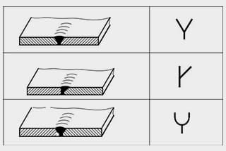
(1) Joint and bevel form
The joint form is selected based on the plate thickness:
When the thickness is between 0.05 mm and 1.6 mm, the joint form shown in the figure below is usually used, and welding is done using microbeam plasma arc.
When the plate thickness is greater than 1.6 mm but less than the material listed in Table 6-4, no bevel is usually made, and welding is done using the perforation method.
When the plate thickness is greater than the limit in Table 6-4, a V-shaped or U-shaped bevel is required for multi-layer welding. Compared to TIG welding, smaller bevels and larger root faces can be used. The maximum allowable value for the root face is equal to the maximum welding thickness for the perforation method. The first layer is welded using the perforation method, and the other layers are welded using fusion method or other welding methods.
(2) Welding current and nozzle aperture
The welding current is always selected based on the plate thickness or penetration requirements. If the current is too low, the weld may not penetrate and no small hole will be formed. If the welding current is too high, the molten metal may droop due to a large hole diameter.
The nozzle aperture is selected based on the welding current, and they should be matched appropriately. It is also related to the flow rate of the plasma gas.
(3) Plasma gas
The plasma gas and shielding gas are usually selected based on the metal being welded and the magnitude of the current. When using high welding currents in plasma arc welding, it is generally advisable to use the same gas for plasma gas and shielding gas, as using different gases may result in poor arc stability.
Table 6-5 lists the typical gases used for high current plasma arc welding of various metals. For low current plasma arc welding, pure argon gas is commonly used as the plasma gas. This is because argon gas has a lower ionization voltage, which ensures easy arc ignition.
The flow rate of the plasma gas directly determines the plasma flow force and penetration capability. The greater the flow rate of the plasma gas, the greater the penetration capability. However, if the flow rate of the plasma gas is too high, the diameter of the small hole may become too large, which may affect the formation of the weld.
Therefore, it is necessary to select an appropriate flow rate of the plasma gas based on the nozzle diameter, type of plasma gas, welding current, and welding speed.
When using the fusion method, it is necessary to reduce the flow rate of the plasma gas appropriately to minimize the plasma flow force.
(4) Welding speed
The welding speed should be selected based on the flow rate of the plasma gas and the welding current, ensuring that all three parameters are appropriately matched. When other conditions are constant, increasing the welding speed reduces the heat input and decreases the diameter of the small hole until it disappears.
However, excessive increase in welding speed may result in undercut or porosity.
On the other hand, if the welding speed is too low, the base metal may become overheated and the molten metal may droop. Therefore, the welding speed, flow rate of the plasma gas, and welding current should be well-matched.
(5) Nozzle-to-workpiece distance
If the distance is too large, the penetration capability decreases. If the distance is too small, it may cause nozzle blockage. Generally, the distance is set between 3 to 8mm. Compared to tungsten inert gas (TIG) welding, the variation in nozzle distance has less impact on the welding quality.
(6) Shielding gas flow rate
The flow rate of the shielding gas should be selected based on the welding current and plasma gas flow rate. Under a certain plasma gas flow rate, excessive flow rate of the shielding gas can disrupt the gas flow, affecting arc stability and protection effectiveness.
On the other hand, too low flow rate of the shielding gas may result in inadequate protection. Therefore, the flow rate of the shielding gas should be in an appropriate proportion to the plasma gas flow rate.
For perforation type welding, the flow rate of the shielding gas is generally in the range of 15 to 30 L/min.
(7) Arc initiation and arc termination
When using the perforation method to weld thick plates, defects such as porosity and undercut are prone to occur at the arc initiation and termination points.
For butt joints, arc initiation and termination plates are used. The arc is first initiated on the initiation plate, then transitioned to the workpiece, and finally terminated on the termination plate, closing the small hole.
However, for circumferential joints, arc initiation and termination plates cannot be used. Instead, a method of gradually increasing the welding current and plasma gas flow rate is used to initiate the arc on the workpiece, and the arc is closed by gradually reducing the current and plasma gas flow rate to close the small hole.
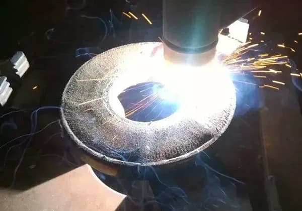
2. Plasma Arc Cutting
1. Cutting Principle
Melting and blowing principle: The plasma arc completely melts the workpiece, and the high-speed mechanical flushing force of the plasma stream blows away the molten metal or non-metal, forming a narrow cut.
1. Can cut any metal: steel, aluminum, tungsten, copper, titanium, molybdenum, etc. Can cut non-metals: such as granite, refractory bricks, concrete, etc.
2. Fast cutting speed and high productivity.
3. Good cut quality: smooth, small heat-affected zone (HAZ), minimal deformation, and the cut is close to vertical.
Disadvantages:
Equipment load, high no-load voltage.
2. Cutting techniques
1. Plasma Gas
1) Types
Argon gas: Low no-load voltage (70-80V), but low arc temperature, suitable for cutting thicknesses less than 30mm.
Nitrogen gas: Due to the endothermic decomposition of nitrogen gas, the arc is further compressed, resulting in a higher arc temperature and higher heat carrying capacity, allowing for increased cutting thickness and speed. No-load voltage higher than 165V.
Nitrogen gas + hydrogen gas: Further increases the arc temperature and heat carrying capacity, allowing for increased cutting thickness and speed. No-load voltage higher than 300V.
Nitrogen gas + argon gas
Air: Low cost, high arc temperature due to exothermic oxidation reactions, allowing for large cutting thicknesses and high cutting speeds. The cutting quality is also good, but the tungsten electrode is prone to oxidation. Therefore, hafnium-copper electrodes or zirconium-copper composite electrodes are often used, as they form an oxide film that prevents further oxidation.
2) Flow rate
The flow rate of plasma gas is much higher than that used in welding, as the plasma arc requires a harder arc.
2. Process Parameters
1) No-load voltage:
It not only affects arc ignition performance but also influences arc stiffness. A higher no-load voltage results in a stronger arc and greater flushing force, allowing for higher cutting speed and thickness.
2) Arc current and voltage:
Increasing the arc current and voltage can increase the cutting thickness and speed, with voltage having a more significant effect. However, increasing the current may lead to the formation of a double arc and larger kerf.
3) Cutting speed:
It is recommended to maximize the speed while ensuring complete penetration. Increasing the cutting speed improves productivity and reduces deformation and the heat-affected zone. Slow cutting speeds result in lower productivity, increased risk of dross formation, and larger heat-affected zone.
4) Nozzle-to-workpiece distance:
Generally, a distance of 8-10mm is preferred. Increasing the distance increases the arc power but also leads to greater heat dissipation, lower arc efficiency, reduced flushing force, and an increased risk of dross formation. It is also more prone to double arcs. Conversely, a distance that is too low may result in nozzle blockage.
As the founder of MachineMFG, I have dedicated over a decade of my career to the metalworking industry. My extensive experience has allowed me to become an expert in the fields of sheet metal fabrication, machining, mechanical engineering, and machine tools for metals. I am constantly thinking, reading, and writing about these subjects, constantly striving to stay at the forefront of my field. Let my knowledge and expertise be an asset to your business.
Imagine a welding technique that offers precision, efficiency, and versatility, all while minimizing defects. Variable Polarity Plasma Arc Welding (VPPAW) achieves just that for aluminum alloys. By independently adjusting current…
Have you ever wondered about the hidden dangers behind the bright sparks of welding? In this article, we explore the harmful effects of argon arc welding on the human body.…
Choosing the right arc welding power source can be a game-changer for any welding project. Have you ever wondered how to pick the most efficient power source for your specific…
Welding aluminum alloys presents unique challenges due to their low melting point and high thermal conductivity. This article dives into various welding methods, such as TIG, MIG, and plasma arc…
What makes welding magnesium alloys so challenging and exciting? In this article, you'll explore innovative techniques like laser welding with silicon carbide, pulsed current plasma arc welding, and activated welding.…
Welding symbols may seem like a foreign language, but mastering them is crucial for effective communication in the world of mechanical engineering. In this blog post, a seasoned mechanical engineer…
Have you ever wondered about the art of welding and the different positions involved? In this fascinating blog post, we'll delve into the intricacies of welding positions, from flat to…
Welding is the backbone of modern manufacturing, but with so many methods available, how do you choose the right one for your project? In this blog post, we'll dive into…
Welding dissimilar metals is a challenging but essential process in modern manufacturing. It involves joining metals with different properties and compositions, often resulting in a fusion zone with varying mechanical…