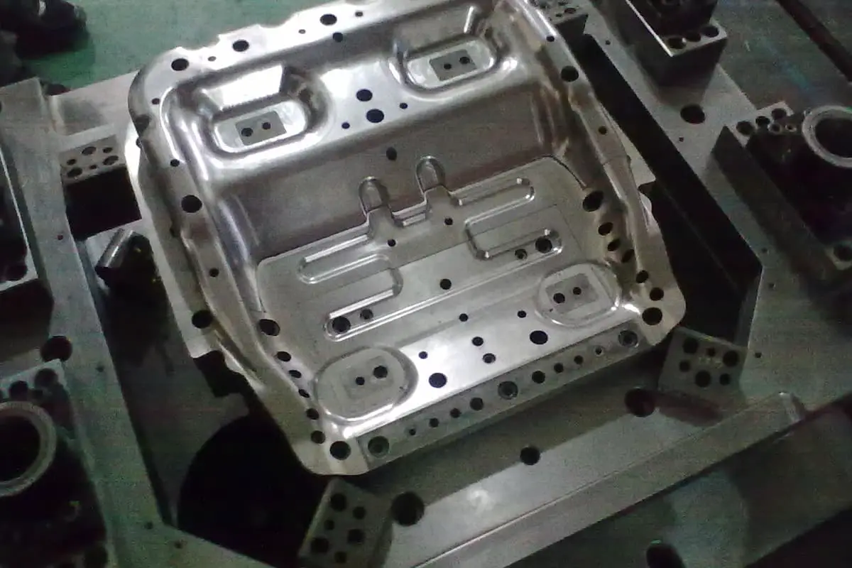
Factors Influencing Wrinkling in Stamped Parts and Solutions
1. Stretch Depth Impact
The resistance to material flow along the die cavity is directly related to stretch depth. Excessive stretch depth on concave and convex curves can cause uneven distribution of deformation resistance, leading to wrinkling. It’s best to avoid excessive depths whenever possible.
2. Adjusting the Blank Holder Force
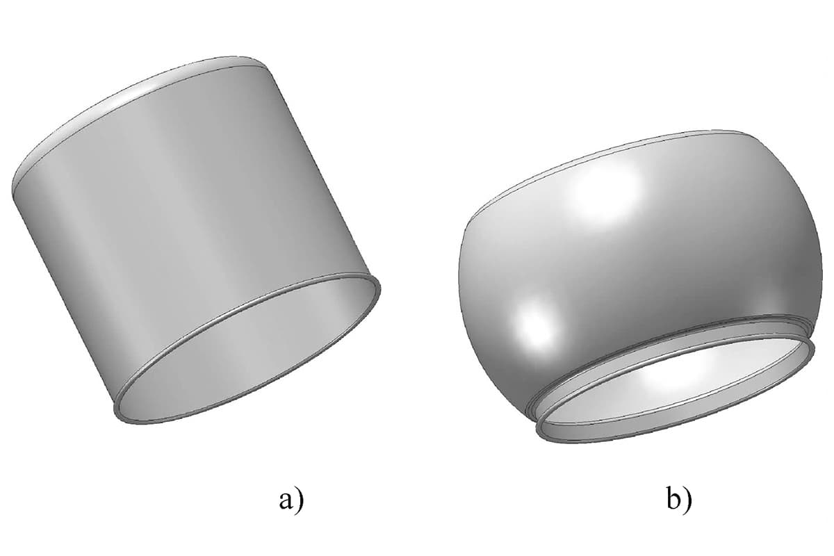
Uniform wrinkles around the part indicate insufficient blank holder force. Gradually increasing the blank holder force can eliminate wrinkles. When drawing conical and hemispherical shapes, most of the material is initially suspended, making sidewall wrinkling likely.
Apart from increasing the blank holder force, it’s also effective to introduce draw beads to increase the radial tensile stress within the sheet, thus eliminating wrinkles.
3. Influence of Die Corner Radius
A large die corner radius reduces the bending resistance encountered by the blank as it flows into the die, increasing the likelihood of wrinkling. A smaller radius increases the bending resistance and reduces the risk of wrinkling but can lead to cracking and tearing in the part.
Extensive production experience has shown that wrinkling in stamped parts mainly results from material accumulation and excessive local material movement speed during stretching. Practical solutions should consider adjusting the corresponding mechanisms in the mold to achieve good results.
Measures to Prevent Wrinkling in Stamped Parts
Preventing wrinkles involves ensuring that the die holds the material in place and controls the flow speed of the sheet during stretching. If the material flows too quickly, wrinkling can occur; conversely, if it flows too slowly, the part can crack.
1. Use of Proper Blank Holders
Blank holders press and hold the deforming section of the blank in place, applying force to prevent the flange from bulging and wrinkling. The force must be appropriate. Blank holders are categorized into elastic and rigid types, where elastic holders are suitable for shallow drawing and rigid holders for deep drawing.
2. Appropriate Use of Draw Beads
Draw beads on the blank holder are an effective method for adjusting and controlling deformation resistance. By regulating material flow, draw beads ensure uniform resistance during stretching, matching the volume of material flowing into the mold cavity to the part’s requirements, thus preventing excess that causes wrinkling or insufficient amounts leading to cracking.
For complex-shaped drawn parts, especially those with small flanges, draw beads should be placed where radial tensile stress is lower, i.e., where the sheet flows easily.
For parts with small flanges, additional material (process allowance) may be added to accommodate draw beads and later removed during trimming. For drawn parts with varying depths, draw beads should be placed in areas with less material flow to prevent excess material from entering the die cavity and causing wrinkling.
Analysis of Causes for Wrinkling in Drawn Parts Wrinkling during the drawing process can arise from several factors:
- Excessive stretch depth in stamping parts, causing material to flow too quickly and form wrinkles.
- A large radius in the die corner during drawing can prevent the punch from holding the sheet in place, leading to rapid material flow and wrinkling.
- Improperly sized or positioned draw beads, failing to effectively slow down the sheet flow, resulting in wrinkling.
- Insufficient pressure from the punch, resulting in incomplete part formation and wrinkling.
- Poor die design and alignment, causing the die to fail in holding the material or creating a small blank holder edge, which allows for rapid material flow and wrinkling during drawing.
- Excessive clearance between the punch and die, leading to inadequate control over the material and wrinkling. These are common causes of wrinkling in the drawing process of stamped parts. Specific problems require detailed analysis to identify precise reasons.