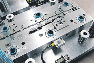
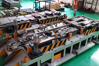
With the continuous improvement of worker wage levels in the stamping industry, reducing the manual manufacturing costs of stamping has become an urgent task for hardware manufacturers. The most commonly used method to achieve this is through the use of continuous die.
Continuous die technology is an effective way to establish a low-cost and efficient automatic stamping production line. However, the precision and complexity of the components required for continuous die pose certain challenges.
Designing continuous die requires more attention to detail than general stamping dies, as precision is critical. This is mainly reflected in the following aspects:
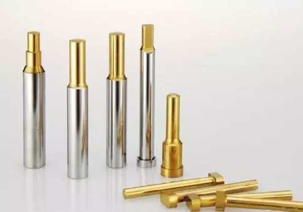
(1) When there are many punching holes, the length of small punch should not be too large
Multi-punch stamping dies can be equipped with punches of varying heights to create a stepped die, which helps to distribute the punching pressure and reduce the load on the punches.
However, it is important to note that when using stepped punches, the smaller punches must be shorter and the larger punches longer to ensure sufficient stiffness. The difference between the two should be equal to the height (sheet thickness).
When using the stepped die, it is recommended to punch the larger hole first and then the smaller hole. This helps to prevent the material from squeezing the smaller punch during the larger punch and causing it to break due to insufficient rigidity.
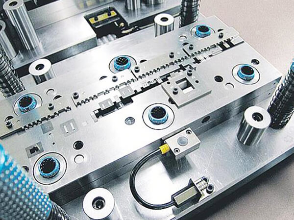
(2) The continuous die shall be equipped with step positioning devices such as retaining material and side edge as far as possible
To ensure the consistent step distance of a continuous die when stamping a workpiece, accurate positioning of the strip is crucial. Several commonly used positioning devices in continuous die include fixed retaining pins, guide pins, guide plates, side edges, etc.
During stamping, preliminary positioning should be done using fixed retaining pins, while guide pins installed in the die should be utilized for correct positioning of the strip during blanking. Side edges, on the other hand, control the feeding distance of the strip material in each step.
The length of the side edge must be equal to the step length plus 0.05-0.5mm, depending on the material thickness.
(3) The guide pin (guide needle) of the continuous die should not be too long
A good positioning device is essential for controlling the feeding step in a continuous die.
Commonly used positioning devices include guide pins, initial stop pins, side edges, and others.
The guide pin is a widely used precision positioning method in continuous dies. When used with a misdelivery detection sensor, it can also sound an alarm and shut down to protect the die. Therefore, it is often utilized in continuous stamping dies.
In high-precision continuous stamping dies, pre-punching is often carried out, followed by using the guide pin to direct the coil in each step. The diameter of the guide pin is usually about 1.2~6mm.
It is important to note that the length of the guide pin should not be too long, and the length entering the guide hole should not be excessive, as it can cause poor die feeding, belt feeding, and other issues.
Therefore, the straight body length of the guide pin of the continuous stamping die should be the thickness of the guide pin fixed formwork plus the thickness of one material.
(4) In the continuous die and other automatic stamping dies, it is not suitable to use urethane and polyhelium ester rubber as stripping elements
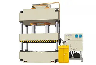
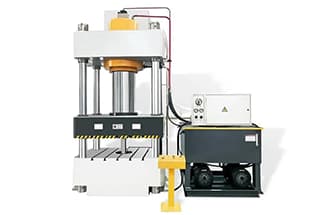
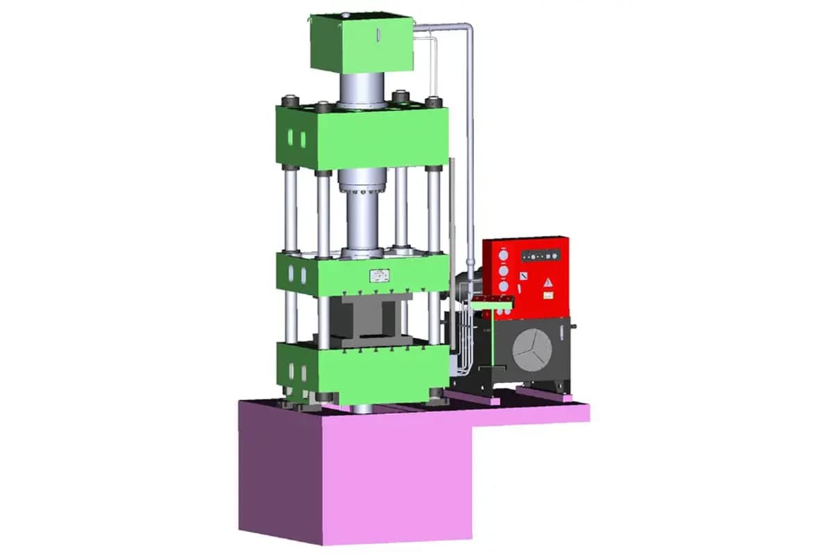
The continuous die is a high-efficiency production die with a service life of 500,000 to 5 million cycles and a punching speed of over 40 times per minute.
When using elastic elements like urethane or polyurethane for unloading, there is a risk of insufficient unloading force and unreliable performance due to their limited service life.
To ensure reliable and normal operation of the continuous die while reducing maintenance, it is recommended to use a spring with a strong service life as the unloading element.
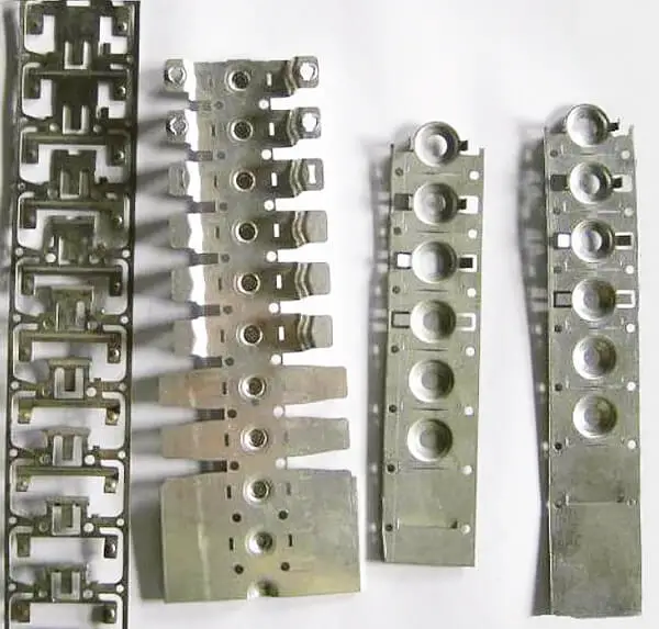
(5) The complex or slender shape in the continuous stamping die should not be punched out at one time
It is not advisable to punch out a complex and slender shape in one go using a continuous die. If possible, the process should be divided into several steps and punched in stages. This approach can make it easier to process the die hole, extend its service life, facilitate die repairs, and improve production efficiency.
(6) Empty steps are reserved in the design to facilitate debugging and mold modification
When designing continuous drawing parts or products with an unstable forming size, the design of an empty station cannot be ignored.
For this type of die, during the layout drawing design, one or two empty stations are often left after the first drawing and forming, providing some flexibility for necessary changes and adjustments after the die test.
For gland parts, an empty station is placed between the first drawing and the second drawing.
Furthermore, if the punch or die orifice is too close, a space should also be reserved on the layout to protect the structures such as punch, die insert, small die base, and cemented carbide insert.
An empty station is reserved between the shaping step and the last blanking step to facilitate the installation of the die and discharge plate and to improve the strength of the die.
(7) Anti chip jumping design
Continuous die is a process of continuously stamping products, especially when there are multiple punching and trimming operations involved.
To prevent product crushing and ensure die stability, an anti-jump waste structure is typically required during the stamping process.
Mainly from the following points:
- The punch is made into a special shape, which can increase the adhesion of waste on the knife edge;
- Add blowing hole for punch;
- The knife-edge shall be in the form of V-shaped or dovetail clamping;
- Reasonable blanking clearance to reduce skip;
- Waste suction device in the mold.
(8) The carrier of continuous mode cannot be deformed
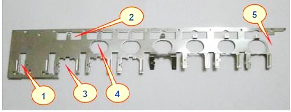
In a continuous die, the workpieces from each process are transferred using overlapping surplus materials as carriers.
During the final blanking process, the workpieces are generally separated from the belt materials.
The overlap used as a carrier in continuous die is called the carrier of continuous modules.
The common carrier forms used in continuous die are the edge carrier, intermediate carrier, double-sided carrier, single-sided carrier, and others.
The edge material carrier is used to punch a guide hole on the residual material’s edge of the workpiece, which helps in locating forming processes such as deep drawing and bending.
Carriers have the advantages of simple design, reliability, and material saving, making them widely used.
The middle carrier cuts most of the materials around the workpiece along the strip, leaving only a small amount of connecting material in the middle of the strip’s width direction. However, this carrier has poor rigidity and poor stability in continuous stamping.
A double-sided carrier is designed to minimize the amount of material left on both sides of the belt, while maintaining rigidity and avoiding deformation. This type of carrier is typically used for continuous stamping of thin materials and workpieces with large feed distances.
On the other hand, a single-sided carrier only leaves a small amount of material on one side of the workpiece. However, it has poor rigidity and is only suitable for continuous stamping of workpieces with thick material and small feed distances.
Since continuous die requires high step accuracy, it is crucial to ensure that the carrier remains rigid and free from deformation in order to maintain dimensional accuracy and improve working stability. Therefore, carrier design is a critical aspect of continuous die design.
To ensure that the carrier has sufficient strength and rigidity, the lap size is often increased appropriately. In cases where a single-sided carrier lacks sufficient strength, double-sided or intermediate carriers can be designed instead.
Additionally, to prevent the deformation of the workpiece from affecting the carrier, a process notch is punched between the carrier and the workpiece to separate them.
(9) Quick disassembly and parts protection
In the design of a continuous die, it is particularly important to ensure quick disassembly of parts and the use of standard parts to prevent errors.
To facilitate rapid mold repair, the entire set of molds is usually not removed from the machine during continuous maintenance. Instead, only the components and templates that require repair are removed individually when the machine is stopped. Therefore, it is crucial to design a quick disassembly structure.
During the replacement of parts and templates, it is common to mistakenly install parts or misalign templates, which can damage the mold. Thus, it is essential to pay attention to the anti-stupidity of the parts and templates to prevent such errors.
Conclusion
The above text shares some personal experience with mold designing. If you’re interested in stamping molds and are facing challenges with hardware manufacturing, please feel free to leave your comments below.