1. Die for Punching As shown in Figure 1, the die used in the punching experiment has an upper mold stroke of 45mm. When the punching process is completed, the distance between the bottom of the upper mold and the upper surface of the lower mold is 0.3mm, as depicted in Figure 2. This arrangement […]
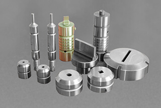
As shown in Figure 1, the die used in the punching experiment has an upper mold stroke of 45mm.

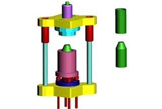
When the punching process is completed, the distance between the bottom of the upper mold and the upper surface of the lower mold is 0.3mm, as depicted in Figure 2.

This arrangement is made to prevent the blade from penetrating too deeply into the lower mold, thereby preventing excessive wear on the upper mold.
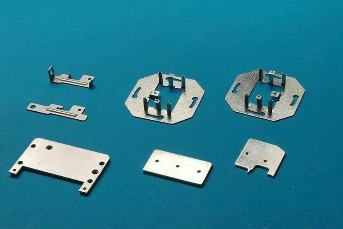
The material used in this experiment is a copper alloy (see Figure 3), with a thickness of 0.23mm.

This experiment utilized four different punching clearances of 0mm, 0.01mm, 0.02mm, and 0.03mm, at two punching speeds of 30mm/s and 80mm/s, making a total of eight experimental parameters.
The experiment was conducted on a press machine specifically designed for punching and used a Keyence digital microscope to observe the shape of the workpiece after punching.
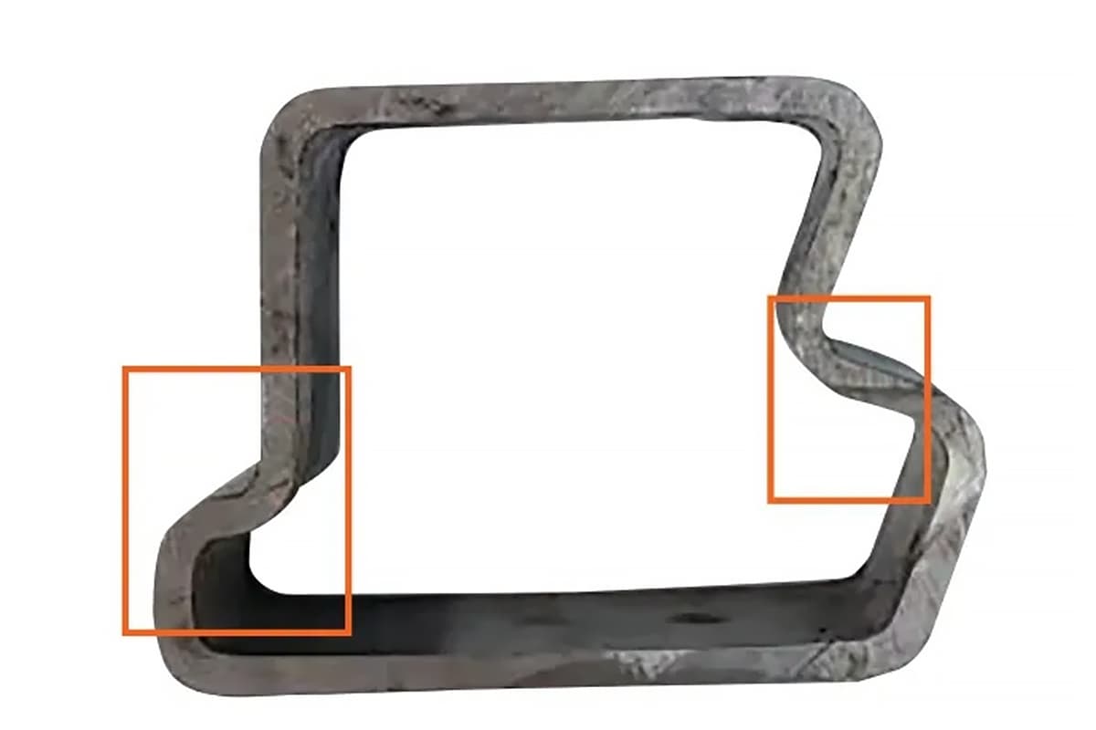
Figure 4 compares the burrs on the punched pieces when the punching speed is 30mm/s, and the punching clearances are 0mm and 0.03mm.

It is clear from Figure 4 that for a clearance of 0mm, the surface of the punched piece is very smooth with no burrs, whereas with a clearance of 0.03mm, burrs remain on the break, measuring approximately 75μm in width.
This could be due to the die’s blade edge rounding off from wear when the clearance is too large, thereby reducing the concentration of stress at the blade edge and causing the crack to appear further from the blade edge.
As the punching speed increases to 80mm/s, the effects of different punching clearances on the punched pieces are noticeably different.
For a clearance of 0mm, the cross-section of the punched piece remains burr-free, but the edge of the workpiece is much more complete than when the speed is 30mm/s (see Figure 5a), almost devoid of material loss due to shearing. Therefore, its surface quality is better than when the speed is 30mm/s.

In contrast, with a clearance of 0.03mm, the burrs on the punched piece are noticeably larger and wider than when the speed is 30mm/s, as shown in Figure 5b. Similar to the case of 0mm clearance, the edge of the workpiece produced at a clearance of 0.03mm is also quite complete.
Figures 6 and 7 present the cross-sectional images of punched pieces formed under two different punching speeds and various punching clearances, magnified 500 times.

Figure 6 illustrates that when the punching clearance is 0mm, the shiny and fractured zones of the punched piece are very noticeable.
Moreover, the shiny zone is wider, while the fractured zone is more flat. This suggests that when the punching speed is 30mm/s and the punching clearance is 0mm, the punched material undergoes a complete process of plastic shearing deformation and fracture.

In the case of a 0.03mm clearance, no distinct shiny and fractured zones appear, but rather noticeable collapsed corners and a gradual plastic flow process are observed.
This reveals that an increase in clearance is unfavorable for the material’s rapid fracture. Too large of a punching clearance weakens the shearing deformation of the material and increases plastic flow, thereby significantly impacting the precision of the punched piece’s cross-section.
On the other hand, when the punching speed increases, as seen from Figure 7a, the shiny zone decreases and the fractured zone enlarges at a 0mm clearance. This indicates that an increase in punching speed accelerates the shearing deformation and fracture process of the punched material.
Figure 7b also demonstrates that even with an increase in clearance under high-speed punching conditions, the shearing deformation and fracture process of the punched piece remain clear and complete. This shows that an increase in punching speed is beneficial for ensuring the quality and precision of the punched piece’s cross-section.
The impact of punching clearance and punching speed on the cross-sectional quality of the punched piece is evident.
For thinner copper alloy punched pieces, choosing a smaller clearance has a direct impact on suppressing burr formation: smaller clearances lead to rapid shearing deformation and fracture processes, resulting in smooth surfaces and a burr-free outcome.
Furthermore, an increase in punching speed can accelerate the elastic and plastic deformation of the material, controlling plastic flow and enhancing surface quality.


