Gears are a common type of spare part used in various industries, including aviation, shipping, and automobiles.
When designing and producing gears, there is a requirement for the number of teeth.
Some people claim that gears with less than 17 teeth cannot rotate, while others argue that this is incorrect and that there are many gears with fewer than 17 teeth.
In reality, both of these statements are correct, and the reason for this discrepancy is open to discussion. If you have any insights, feel free to share them in the comments.
Why is the number of teeth 17?
Why is the number 17 significant and not another number?
The significance of 17 relates to gear processing methods, as depicted in the illustration below. A common method is to use a hob for cutting.
When gears are manufactured in this manner, undercutting can occur when the number of teeth is limited, leading to a decrease in the strength of the produced gears.
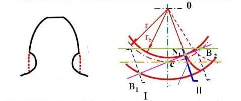
What is root cutting? Note the red box in the figure:
When the point where the top of the tooth intersects with the meshing line of the gear extends past the limit for the meshing point of the gear to be cut, a portion of the involute tooth profile of the gear to be cut’s tooth root is removed. This is referred to as undercutting.
Undercutting of tooth profile:
In the process of cutting gears using the generating method, it may occur that the cutter removes a portion of the involute tooth profile at the root of the gear tooth. This is known as undercutting.
Reasons for undercutting:
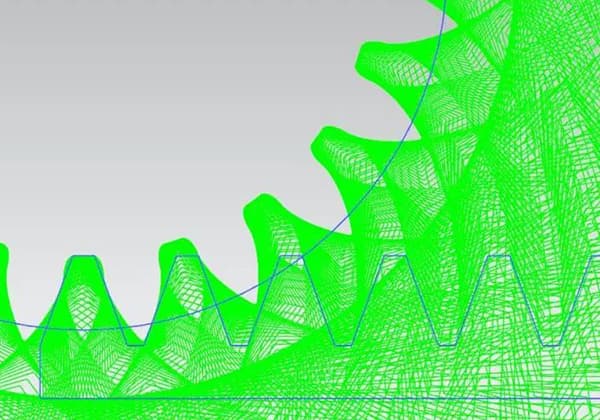
When the intersection of the top line of the tool tooth and the meshing line exceeds the meshing limit point N1 and the tool continues to move from position II, a portion of the involute tooth profile that was previously cut at the root will be cut again.
Undercutting can be avoided when the addendum height coefficient is 1 and the pressure angle is 20 degrees.
For proper gear operation, a transmission relationship must be formed between the upper and lower gears, allowing for smooth rotation. This is especially true for involute gears, where a well-meshed gear pair is crucial for their functioning.
There are two types of cylindrical gears: straight and helical. For standard spur gears, the coefficient of tooth top height is 1, the coefficient of tooth heel height is 1.25, and the pressure angle must be 20 degrees.
In gear processing, the tooth germ and the cutter are similar to two gears. If the number of teeth on the germ is less than a certain value, part of the root of the tooth will be removed, known as undercutting. This can affect the strength and stability of the gear if the undercutting is significant.
The number 17 mentioned is specific to gears. The number of teeth doesn’t affect the efficiency of the gears, but 17 is a prime number, meaning the number of overlapping cycles between a gear tooth and other gears is the lowest under a certain number of cycles, resulting in minimal force being applied at that point.
Gears are precision instruments, and although errors can occur, the likelihood of axle wear is low for 17. However, 17 may be sufficient for a short time, but not for a long period.
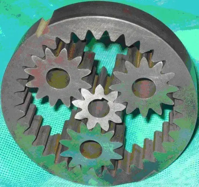
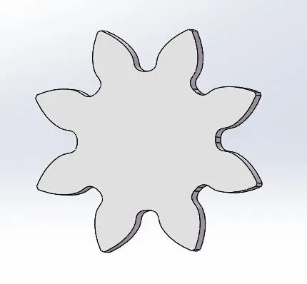
Despite this, there are many gears with fewer than 17 teeth on the market that still function well, as shown in the accompanying image.
Some netizens have pointed out that it is possible to manufacture standard involute gears with a number of teeth less than 17 by changing the manufacturing process. However, such gears can still become stuck during use due to gear interference. There are several solutions to this issue, including modifying the gear or using a different type of gear, such as helical gears or hypocycloid gears.
One netizen has noted that the commonly accepted idea that the number of teeth for involute spur gears must be greater than 17 to avoid undercutting is based on the assumption that the top fillet R of the rack cutter for machining gears is 0. However, in industrial production, it is unlikely that the cutters have no R angle as this would lead to stress concentration, making the cutter prone to cracking or wearing during use.
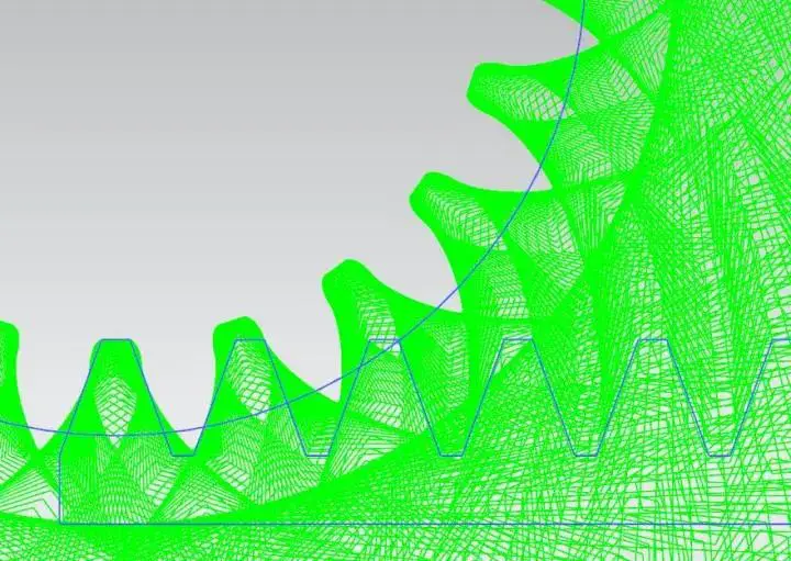
Furthermore, even if the cutter does have an R angle, the number of teeth for undercutting may not be 17, so the statement that 17 teeth is the limit for undercutting is open to debate. The accompanying images further illustrate this point.
It is evident from the figure that there is no noticeable variation in the tooth root transition curve from 15 teeth to 18 teeth when processing the gear with a cutter that has an R angle of 0 at the top of the rake face.
However, why does the number of teeth with involute straight teeth start to undercut at 17 teeth?
The picture was created by a mechanical engineering professional.
It is apparent that the R angle size of the cutter influences the gear undercutting.
The purple extended epicycloid equidistant curve in the above figure represents the profile of the tooth root after undergoing undercutting.
The impact of the undercutting of a gear’s tooth root on its use is determined by the relative movement of the top of the other gear and the strength reserve of the gear root.
If the top of the paired gear does not engage with the undercut portion, the gears can rotate smoothly. (Note: The undercut portion has a non-involute profile, and the engagement between a non-involute profile and an involute profile is usually not conjugate in the absence of a special design, resulting in interference.)
The figure shows that the meshing line of the two gears just engages the maximum diameter circle opposite the transition curve of the two gears. (Note: The purple section represents the involute profile, the yellow section represents the undercut part, and the meshing line cannot penetrate below the base circle as there is no involute below the base circle, and the meshing points of the two gears at any position are on this line.) This means the gears can engage normally.
However, this is not acceptable in engineering.
The length of the meshing line is 142.2, and this value divided by the base pitch equals coincidence.
Others argue that this issue is incorrect and the use of gears with fewer than 17 teeth will not be impacted. (The previous answer’s description of this point was incorrect, and the three conditions for correct meshing of gears have nothing to do with the number of teeth.)
Although 17 teeth may be difficult to process under certain conditions, it is worth noting that more knowledge about gears is available.
The involute is the most commonly used type of gear tooth profile. Why is it an involute?
What distinguishes this line from a straight line or an arc?
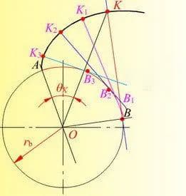
As shown in the figure below, it is an involute (only half a tooth’s involute is shown here).
In summary, an involute is the path traced by a straight line and its fixed point as the line rolls along a circle.
Its advantages are clear.
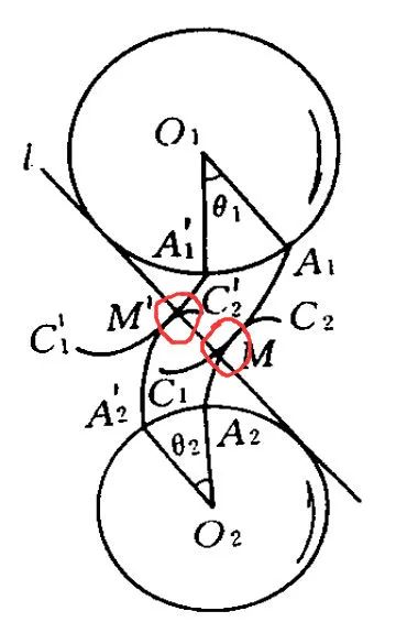
When two involutes engage with each other, as depicted in the figure below.
When two wheels rotate, the force on the contact point (such as M, M’) acts in the same direction along a straight line, which is perpendicular to the contact surface (section) of the two involutes.
Due to this perpendicularity, there is no “slip” or “friction” between them, reducing friction in the gear mesh, improving efficiency and extending the life of the gear.
However, involute is not the only option as the most widely used form of tooth profile.
As engineers, we must consider not only the feasibility and effectiveness of a theory, but also the practical aspects of its implementation, including material selection, manufacturing, precision, testing, and other aspects.
The commonly used processing methods for gears are divided into forming methods and generating cutting.
The forming method involves directly cutting the tooth profile by using a cutter that corresponds to the gap shape between the teeth, including milling cutters and butterfly wheels.
Generating cutting is more complex. It involves engaging two gears, one of which is hard (tool) and the other is still rough. The process of engagement starts from a distance and gradually moves to a normal meshing state, generating new gears through cutting.
Generating cutting is widely used, but when the number of gear teeth is small, the intersection of the cutter’s top line and the meshing line will occur, exceeding the meshing limit point of the gear being cut. In this case, the root of the gear being machined will be cut off.
Although the undercut part does not affect normal meshing of the gear, it weakens the strength of the gear teeth. When used in heavy-load situations such as a gearbox, the gear teeth may easily break.
The figure shows a model (with undercut) of a 2-die 8-tooth gear after normal machining.
However, 17 teeth is the limited number calculated based on the gear standards in China.
When the number of teeth is less than 17, undercutting will occur during normal processing using generating cutting.
In this case, it is necessary to adjust the processing method, such as modification. The figure shows a 2-mode 8-tooth gear (with minimal undercutting) processed through modification.
It is important to note that the information described here is not exhaustive.
Mechanical engineering involves many fascinating aspects and presents numerous challenges in manufacturing components.
In conclusion, the number of 17 teeth arises from the processing method and is dependent on the method used.
If the gear processing methods are altered or improved, such as through forming methods or modification processing (specifically referring to straight cylindrical gears), undercutting will not occur, and the limitation of 17 teeth will not be an issue.
This question and its answer highlight one of the defining traits of mechanical science – the close relationship between theory and practice.
Netizens’ opinion: It is incorrect to state that a gear cannot rotate if it has fewer than 17 teeth. This section will briefly explain the origin of the 17 teeth number.
Gear refers to a mechanical component equipped with teeth on its rim that continuously mesh and transfer motion and power. The profile of a gear can include involute, circular arc, etc. and among these, involute gears are widely used. Involute gears can further be divided into straight cylindrical gears and helical cylindrical gears, among others.
For standard straight cylindrical gears, the addendum height coefficient is 1, the dedendum height coefficient is 1.25, and the pressure angle is 20°. Gears are typically processed using generating cutting, where the motion of the cutter and the gear blank resembles the meshing of two gears.
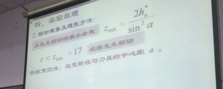
For standard gear processing, if the number of teeth is less than a certain value, a portion of the involute profile at the root of the gear blank may be removed, known as undercutting. This can severely affect the strength and transmission stability of the gear, as shown in the left figure below. To avoid undercutting, the minimum number of teeth required is 2 * 1/sin (20) ^ 2 (where 1 is the addendum coefficient and 20 is the pressure angle). For standard straight cylindrical gears, this minimum number is 17 teeth.
There are various ways to avoid undercutting, such as by using gear deflection, where the tool is positioned either far away from or close to the wheel blank’s rotation center. To avoid undercutting, it is recommended to position the tool far away from the contour rotation center, as shown in the figure on the right, resulting in a complete involute contour.
After proper modification, the gear can rotate without being impacted. This is also possible for gears with only five teeth.
Helical gears can also effectively avoid undercutting or lower the minimum number of teeth required to prevent undercutting.
This calculation is based on mathematical principles. It is not to say that gears with fewer than 17 teeth cannot rotate, but if there are fewer than 17 teeth, it is more likely that a portion of the gear root will be cut during gear processing, known as undercutting. This can weaken the strength of the gear.
The pressure angle a=20 degrees and the minimum number of teeth without undercutting is 17, as determined by the formula mentioned above.
Some users have expressed the opinion that whether the number of teeth can be less than 17 is a topic worth considering. However, for standard gears, the number of teeth cannot be less than 17. This is because when the number of teeth is less than 17, the gear is prone to undercutting.
Undercutting occurs when using the generating method to cut teeth and the tooth tip of the cutter cuts too far into the root of the gear tooth, thereby cutting a portion of the involute tooth profile of the tooth root.
Generating cutting and Radical Cutting
Generating cutting
The generating cutting method is a process used in machining gears that follows the principle of geometry known as the envelope. This method involves the use of two gears with involute tooth profiles. The angular velocity of the driven gear can be determined by engaging the two tooth profiles and meshing them together. The relationship between the angular velocity of the driving gear (w1) and the driven gear (w2) is fixed and is represented by i12 = w1/w2.
During the engagement of the two tooth profiles, the pitch circles of the gears roll against each other in a pure rolling motion. As a result, the tooth profile of the driving gear will occupy a series of relative positions with respect to the driven gear. The envelope of these positions is the tooth profile of the driven gear. This means that when the two pitch circles are in pure rolling motion, the involute tooth profiles of the gears can be considered as enveloping lines that are mutual to each other.
Undercutting phenomenon
Reasons for Undercutting:
Undercutting occurs when the intersection point of the tool’s tooth top line and the meshing line surpasses the meshing limit point N1, and the tool continues to move from position II. This results in the re-cutting of a portion of the involute tooth profile that was previously cut at the root.
For non-standard gears, it is mentioned that the number of teeth is less than 17.
Consequences of Undercutting:
Undercutting can have significant consequences for the performance and strength of gears. On the one hand, it weakens the bending strength of the gear teeth, making them more susceptible to failure under load. On the other hand, it also reduces the engagement of the gear transmission, which is unfavorable for transmission efficiency.