Deformation of Large CNC Press Brake Ram Solutions
Why do CNC press brake rams deform, causing costly production delays? This article explores the common causes of ram deformation in CNC press brakes, from prolonged usage to material stresses,…
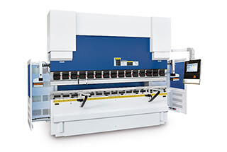
Have you ever wondered what makes a CNC press brake so precise and powerful? This article delves into the essential components that contribute to its efficiency, from the robust bed and ram to the intricate hydraulic system and CNC controls. By exploring the main structure, you’ll gain insights into how each part works together to ensure accurate and high-quality metal bending. Dive in to learn how these elements enhance performance and reliability in modern metalworking.

The CNC press brake is mainly composed of bed, ram, hydraulic system, rear stop, punch and die, protective barrier, electrical control system and front support frame.
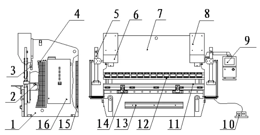
| 1. Body | 9. CNC system |
| 2. Rear material retaining device | 10. Foot switch |
| 3. Grating ruler | 11. Top punch |
| 4. Left and right shields | 12. Bottom die |
| 5. Safety laser barrier | 13. Front shield and compensation cylinder |
| 6. Left cylinder (Y1) | 14. Front support frame |
| 7. Ram | 15. Rear guardrail |
| 8. Right oil cylinder (Y2) | 16. Electrical box |
The bed is welded with steel plates and processed as a whole to ensure the rigidity and machining accuracy of the body.
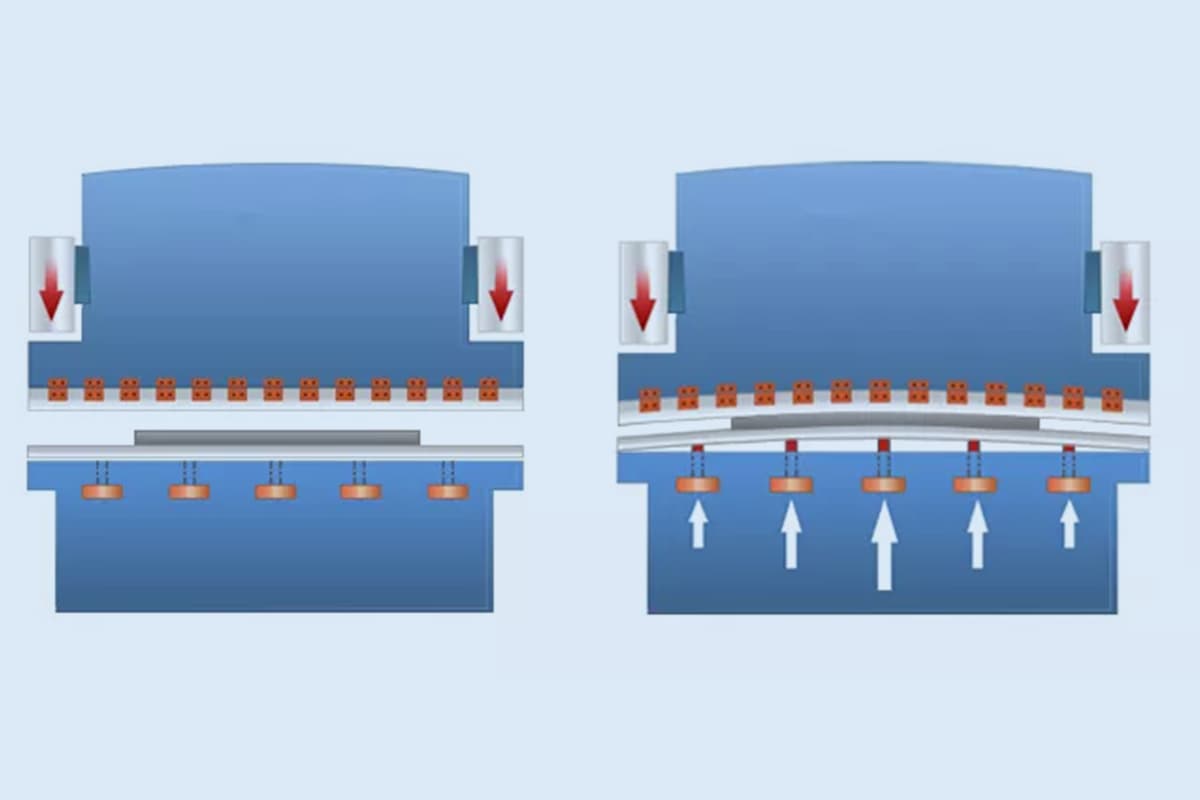
The bed worktable adopts a three-plate structure and hydraulic convex automatic compensation system, which solves the deformation of the worktable and ram during the sheet metal bending process and its impact on the quality of the bent workpiece.
The compensation amount is automatically adjusted by the CNC system, which is convenient and accurate, and can effectively improve the accuracy of sheet metal bending.
The main board of the ram is welded from a whole steel plate and a guide rail, and it is connected to the cylinder piston rod through bolts. The oil cylinder is fixed on the oil cylinder connecting plate above the left and right side plates of the bed. Through the hydraulic servo synchronous control system, the piston rod drives the ram to move up and down. The synchronous control precision is high, which can effectively improve the repeated positioning accuracy of the ram and the accuracy of bending the sheet metal.
The hydraulic system of the CNC press brake adopts an integrated hydraulic control system, which effectively reduces the installation of pipelines, overcomes the phenomenon of oil leakage, is convenient for maintenance, improves the working stability of the machine, and makes the appearance of the machine more beautiful and concise.
The CNC press brake is equipped with a high-speed and large lead backgauge mechanism that is driven by a linear guide rail and ball screw.
The system can control up to six axes based on the user’s needs, including X1 and X2 axes in the front and rear directions, R1 and R2 axes in the up and down directions, and Z1 and Z2 axes in the left and right directions, which facilitates workpiece positioning.
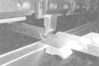
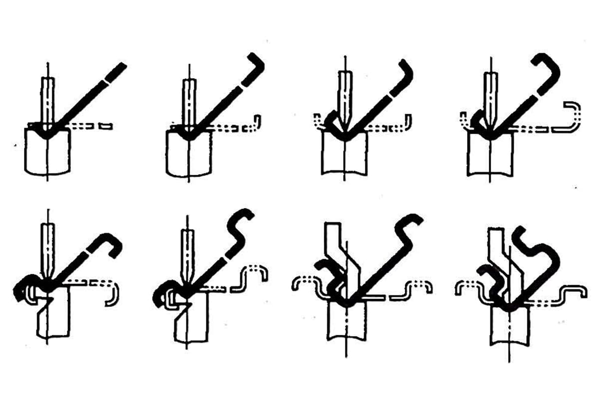
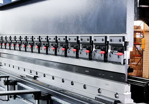
According to the users’ needs, sectional upper dies with varying lengths can be equipped. These can be assembled into a specific length to meet the processing requirements of special workpieces.
The equipment can also be fitted with an upper die hydraulic clamping device or a mechanical fast clamping device to reduce workers’ labor intensity and improve production efficiency.
The CNC system utilizes advanced press brake control systems from well-known brands such as Delem, Esa, Cybtouch, and Estun, making it among the most advanced systems in the world.
Protective barriers are installed on the left, right, and rear sides of the press brake to prevent machine operators or outsiders from accessing the hazardous area when the machine is in operation. As per user requirements, an upper limit switch can be installed on the inner side of these guardrails.
If the protective fence is opened while the machine is in operation, the safety protection alarm indicator will turn on, and the machine will stop functioning. After the operator resets the protective fence and presses the reset button, the machine can resume operations.
The front support frame is mounted on the front plate of the machine, making it convenient for holding large-sized workpieces for bending and forming.
The distance between the two supporting frames can be adjusted as per requirements, and the height can also be modified based on the height of various lower molds to accommodate the bending requirements of plates of different sizes.

As the founder of MachineMFG, I have dedicated over a decade of my career to the metalworking industry. My extensive experience has allowed me to become an expert in the fields of sheet metal fabrication, machining, mechanical engineering, and machine tools for metals. I am constantly thinking, reading, and writing about these subjects, constantly striving to stay at the forefront of my field. Let my knowledge and expertise be an asset to your business.