Press Brake Operation Manual (Training PDF)
Attention all mechanics and engineering enthusiasts! Have you ever wondered about the ins and outs of operating a press brake machine? In this blog post, we'll dive into the world…
Have you ever wondered how a press brake shapes metal with such precision? This article unveils the fascinating parts and functions of a press brake, showing you its essential role in manufacturing. By the end, you’ll grasp how each component contributes to its powerful performance.
Press braking is carried out on items with a high area-to-volume ratio.
Most sheet metal processed on press brakes is thinner than 6 mm. The machines used to bend sheet metal are called press brakes, which in most cases are hydraulically or electrically powered machines with numerical control.
They are very common in the metalworking field. They function by giving sheet metal an angled or rounded shape through the use of a punch and a concave die.
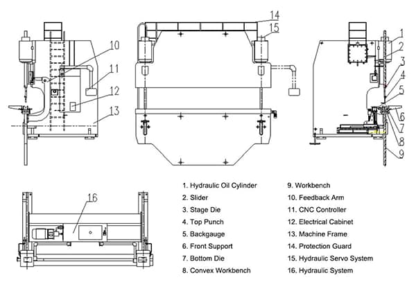
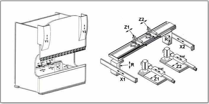
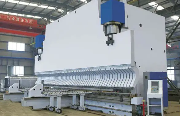
In order to define a common lexicon for this handbook, let’s briefly analyze the components of a press brake.
In the diagram below you can see the components that we will analyze in the following chapters.
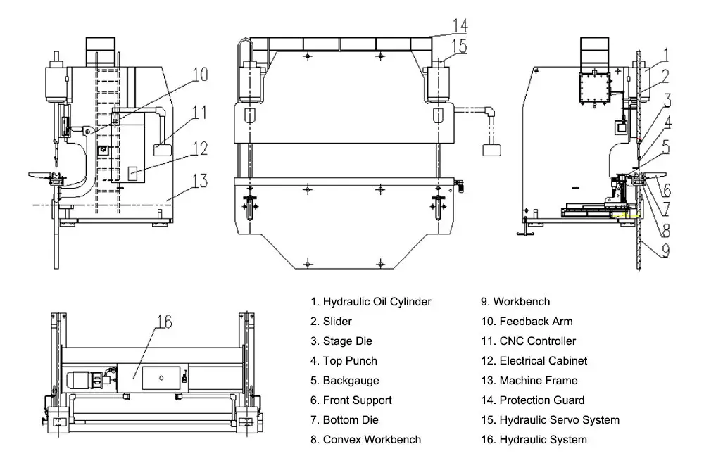
The press brake machine is made up of an oil cylinder, a hydraulic system, a grating ruler position feedback system, a ram, a frame, and various tools, typically comprises four main components:
Let’s explore each part in more detail.
The press brake’s frame is constructed from the welding of the left and right upright plates, the worktable, supporting bodies, and fuel tanks. The worktable is positioned beneath the left and right uprights, while the fuel tank is welded with the uprights.
This design enhances the frame’s rigidity and strength, as well as expands the area for the dissipation of heat from the hydraulic oil.
Features of the Press Brake Structure:
Press brake structure is the frame that supports the ram and it is welded to the lower table, it usually consists of two parts with a “C” shape in the back.
Further reading:

Press brake numerical control is a common featureof machines tools.
Numerically controlled machine tools or NC machine tools are machine tools whose operation is controlled by a computer integrated into the machine.
This computer governs the movements and functions of the machine in accordance with a specific working program.
Thanks to an encoder in the numerical control, it measures the positions of its moving parts and activates actuators, (motors, hydraulic pistons or others), which control the machine movements and position the tool at a specific arbitrarily chosen point.
A given movement of the machine measured by an encoder and controlled by a computer by means of a motor that can position the machine precisely at an arbitrary point along the available stroke is called controlled axis or simply machine axis.
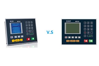
In addition to selecting the dimensions or features of a press brake, a buyer can choose from a number of different numerical control types, which are, mounted at one end of the machine, and are the main control point from which programming of the entire system takes place.
Numerical control types on the market differ in the number of axes they can control and in their ability to produce a video simulation of the bending sequence.

The ram of the press brake is constructed from a solid steel plate and is connected to the piston rod in the center of the left and right hydraulic cylinders. The cylinder is secured to the connecting plate of the left and right wall plates and the piston rod is driven by hydraulic power to move the slider up and down.
To ensure accurate positioning of the ram at the upper dead point, grating rulers are placed on both sides of the ram to transmit position information back to the NC controller, which then adjusts the position. This also ensures the synchronized operation of the ram.
The ram utilizes hydraulic transmission and its system consists of the ram, hydraulic cylinder, and a mechanical stopper for fine adjustment. The left and right cylinders are attached to the frame, and the piston is driven by hydraulic pressure to move the ram up and down. The mechanical stopper is controlled by the numerical control system.
Further reading:
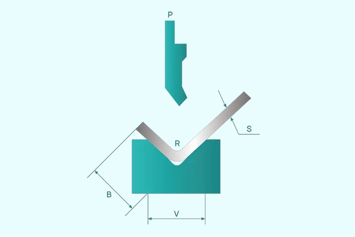
Stroke indicates the maximum available movement along the Y axis. This
dimension is extremely important for checking the possibility of using tall
punches. In such cases the operator must check that: [Daylight – die height
(from base to V bottom) – punch height (from upper beam to punch tip) –
sheet metal thickness < machine stroke.
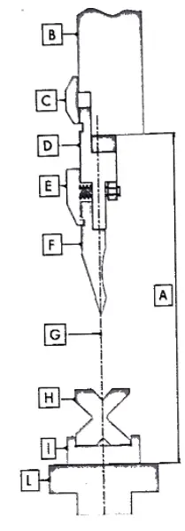
The diagram on the above shows a cross section of a press brake with a Promecam-Amada standard tool.
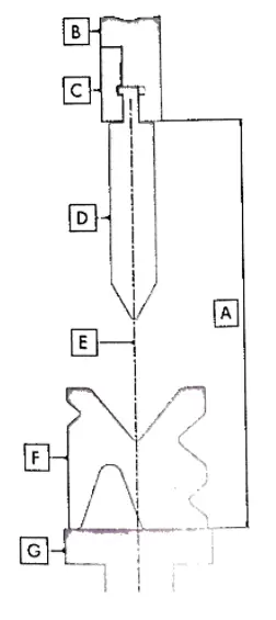
The image above, on the other hand, shows a press brake with an axial tool (Trumpf, Beyeler, etc…) In this case the punch is clamped directly into the upper beam and the press brake axis goes through both punch and tip.
The back stopper moves forwards and backwards through the operation of a motor, and the CNC controller controls its moving distance with a minimum reading of 0.01mm. There are stroke limit switches at both the front and back positions to limit the movement of the back stopper.
Further reading:
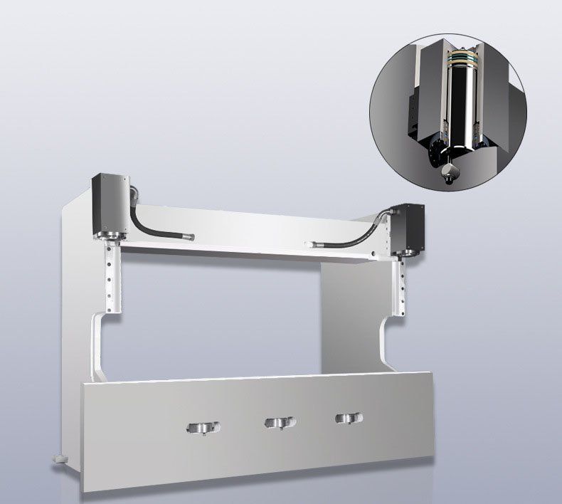
Synchronization System
The mechanical synchronization mechanism is made up of components such as torsion, swing arm, and joint bearings. It has a straightforward design, provides stable and reliable performance, and boasts high synchronization precision.
The position of the mechanical press brake stops is adjusted through the operation of a motor, and the data is controlled by the CNC controller.
Further reading:
| Axis | Description |
|---|---|
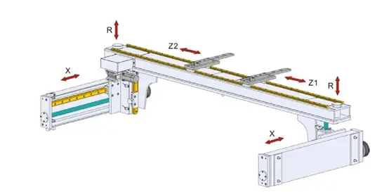
| X Axis | Controls the back and forth movement of the rear stop. In systems equipped with an X1 axis, it additionally controls the left finger. |
| R Axis | Manages the vertical lift (up and down movement) of the rear stop. |
| Z1 and Z2 Axes | Responsible for the movement of the left (Z1) and right (Z2) stop fingers, allowing them to move left and right along the backgauge beam. |
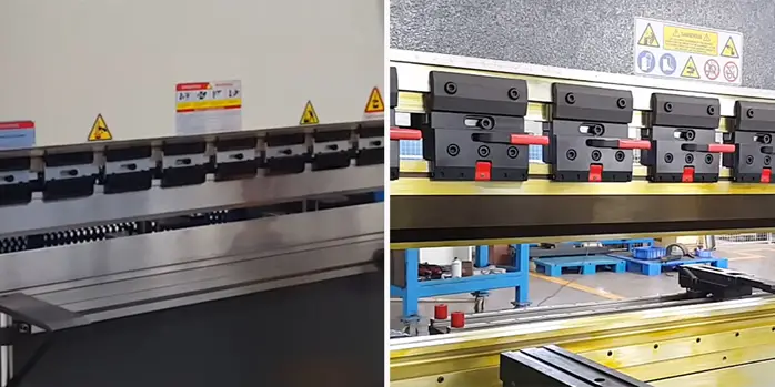
BACK GAUGES are the reference points for positioning the sheet metal. The sheet metal is laid onto dies and then pushed against the back gauges. Their movement, governed by numerical control, follows the working program entered by the operator.
Back gauges can usually y rotate upwards because, during bending, the sheet metal may collide with the lower part of a back gauge and lift it.
However, some types of back gauges make sure that the sheet metal is always stable for every kind of profile
The CNC press brake’s back gauge uses motor-driven transmission to achieve synchronized movement through the use of two ball screws and a timing belt. The back gauge’s distance is controlled by the CNC controller.
THE MAIN AXES of a press brake are X, Y, Z and R. The X, Y and Z axes can be driven by the numerical control or by the operator depending on the features of the press brake.
The directions of the press brake in the X, Y, and Z axes are indicated by the positive arrow in the figure.
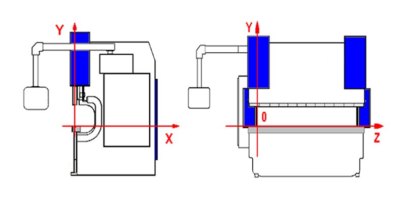
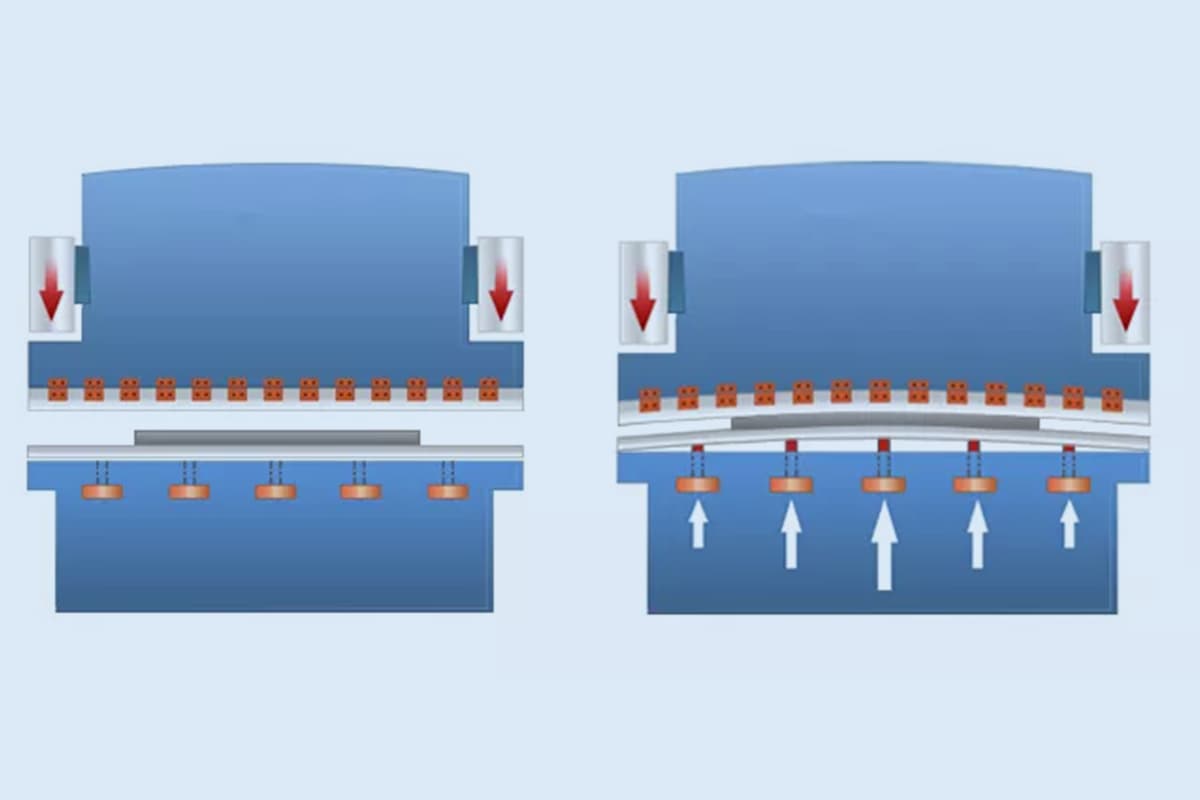
Y Axis: the upper beam moves along this axis (up and down) and as it does so, the bend angle changes. During the bending phase the operator must check that the Y1 and Y2 axes are aligned, because a 0.05mm difference in a 3m machine would cause a 1° difference between the two sides of the table.
The operator must therefore check the alignment of the two pistons before starting bending by zeroing the machine using the appropriate NC button.
Should any problems arise, the operator must check the condition of the surface of the upper can modify the Y axis.
X Axis: this axis determines the bending depth, i.e. the distance between the back gauges and the centre of the die.
The cross-bar where the back gauges are mounted moves along the X axis towards and away from the Y axis.
Z Axis: back gauges move along the cross-bar on which they are mounted and each stops in a specific position depending on the length of the sheet metal and on the part of the press brake where the bending is to be carried out (in the middle or to one side of the press brake).
In a press brake there are a minimum of 2 and a maximum of 4 back gauges. The operator must know the limits of movement along the Z axis, for example, the maximum movement allowed along the table or the minimum distance between two back gauges.
R Axis: the R axis adjusts the cross-bar in height, so that back gauges always adapt to dies with different height and sheet metal always rests against theback gauges.
The press brake axes can be categorized as follows:
Note: The position of the ram can be programmed using either an absolute value equation or an angular value.
The location of each control axis of the press brake is presented in the table below:
| Axis | Zero position | Actual value |
|---|---|---|
| Y1 ram left(Up or down) | Work surface | Distance from the surface of the table to the upper die |
| Y2 ram right(Up or down) | Work surface | Distance from the surface of the table to the upper die |
| X、X1、X2 backgauge〔back and forth〕 | Lower die center | Maximum distance from the center of the lower die to the back gauge |
| R、R1、R2 backgauge(Up and down) | Lower die surface | The distance from the lowest point of the back gauge to the highest point of the back gauge |
| Z1 backgauge left〔Left to right〕 | Machine left side | The distance from the leftmost side of the machine to the center of the left backgauge head |
| Z2 backgauge right(Right to left) | Machine right side | The distance from the rightmost side of the machine to the center of the left backgauge head |
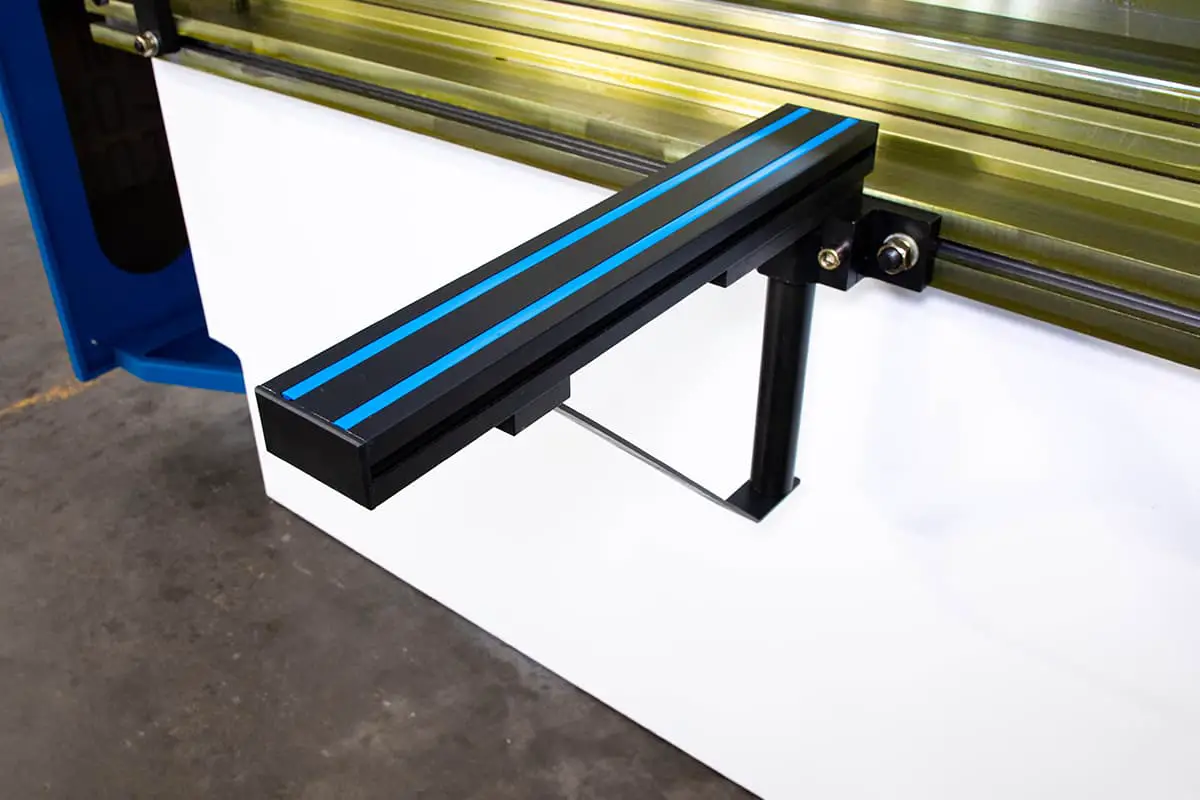
The front support arms of the press brake are attached to the T-groove or linear guide located in front of the machine. They have been designed with a manually adjustable back position claw.
FRONT SHEET SUPPORTING ARMS are optional items of equipment that support the sheet metal during press braking and prevent it from falling during the upper beam return.
They are mostly used during the bending of heavy or big sheets of metal but there are differenttypes of supporting arms to help the operator during bending.
The pedal switch of the press brake primarily serves to control the movement of the top punch during the bending operation, raising and lowering it. Additionally, there is an emergency button located on top of the pedal switch for emergency situations.

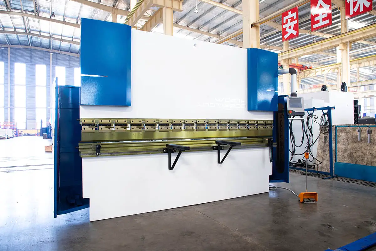
The press brake clamps consist of standard clamps and fast clamping tools that are used for quickly changing the top punch. The use of fast clamping tools significantly simplifies the process of changing the punch die, making it not only convenient but also time-efficient.
Further reading:
Kits and accessories
| 1 | User Manual | 1 Copy |
| 2 | Foundation Screw | 4 Pieces |
| 3 | Washer | 4 Pieces |
| 4 | Oil Gun | 1 Set |
| 5 | Front Supporter | 2 Pieces |
| 6 | Pedal Switch | 1 Set |

During press braking the sheet metal is hand-moved and positioned by the operator, who therefore is forced to stay very close to a running press brake.
For this reason and to comply with the strict safety rules in force, press brakes are provided with safety devices, which on the one hand protect the operator’s safety, and on the other slow down the production cycle.
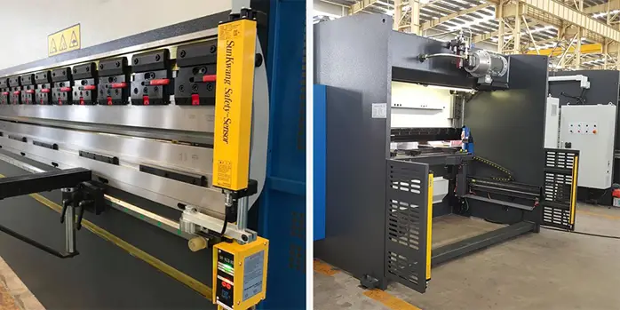
Whereas the back and sides of a press brake are protected by covers or panels, the front, which must always be accessible to the operator, is the most dangerous. It can be protected in two different ways: fixed photo-electric guards or a laser protection system.
In the first case two photoelectric guards mounted at either end of the working zone protect the entire front area up to a distance of 400mm from the machine. If during the rapid descent of the upper beam, the light beams of the guards detect an object in the working area that is of a thickness greater than the material to be bent (for example, the operator’s arm), the safety devices interact with the system management electronics and immediately halt the press.
With the laser protection system only the area near the punch tip is protected. It consists of two photoelectric devices, one transmitting and the other receiving, which can be adjusted manually and which are mounted at either end of the press brake upper beam.
They create a beam of light that moves vertically along with the upper beam to which they are affixed and for this reason they only protect the area belowthe punch.
Typically, the press brake is equipped with a steel fence for the safety of the workers. If a higher level of safety is desired, the use of a light curtain safety device and a laser protection device can be considered.

I am aware that a certain degree of safety must be achieved for a machine to be considered safe for use. Given this, I would recommend equipping the press brake with at least a light curtain device for safety purposes.
Press Brake Safety Guards
Press Brake Light Curtains

Press Brake Laser Guard
Further reading:
The commonly used press brake gauges include angle gauges, angle rulers, and verniers.

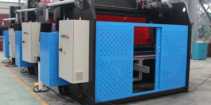
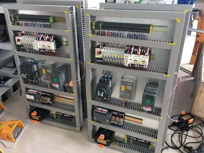
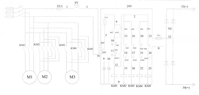
The electric control system consists of an electrical control cabinet, a numerical control system console, and an operator station.
The press brake is powered by a three-phase AC 50Hz 380V power supply (which can be customized). This power source can not only be utilized directly for the operation of the main motor, but also for the rear gear servo and for illuminating the equipment after the AC voltage has been output through the internal system transformer.
The power source is then transformed into two sets of DC 24V after rectification. One set is used for the CNC controller and the other for the control loop.
Different manufacturers may have different designs for their press brake wiring diagrams. Upon purchase, the supplier should provide the wiring diagram, along with the hydraulic diagram and installation and operation manuals. If these are not included with the machine upon receipt, it is recommended to immediately contact the supplier.
Please note that the following press brake wiring diagram is just for reference and is from us.
Development of electro hydraulic proportional technology
During the latter part of World War II, the speed of jet fighters was constantly improving, requiring more advanced control systems with higher requirements for rapidity, dynamic accuracy, and dynamic rate.
In 1940, the first electro-hydraulic servo system appeared on aircrafts. In the 1960s, various types of electro-hydraulic servo valves were developed, leading to a more mature electro-hydraulic servo technology.
However, by the late 1960s, the demand for electro-hydraulic servo technology in civil engineering was growing, but the traditional electro-hydraulic servo valve had strict requirements for fluid medium and consumed a lot of energy, making it expensive to manufacture and maintain.

In the 1970s, in order to develop a reliable electro-hydraulic servo control technology that met the actual needs of engineering, electro-hydraulic proportional control technology rapidly advanced. At the same time, industrial servo control technology also evolved.
Electro-hydraulic proportional technology is a comprehensive approach that combines hydraulic power transmission with the flexibility and accuracy of electronic control. With the advancement of numerical control technology and the availability of reliable proportional hydraulic components, electro-hydraulic proportional control technology has been widely adopted in recent years, with a typical application being the synchronous control of press brake machines.
The basic theory of hydraulic transmission is Pascal principle.

The motor, oil pump, and valve are connected to the fuel tank. To ensure that the oil tank is adequately filled with oil during rapid movement of the ram, a filling valve structure is employed. This not only improves the speed of the ram’s travel, but also saves energy.
The hydraulic control of CNC press brakes requires a high degree of automation and standardization in the manufacturing process. As a result, the press brake must integrate the hydraulic system into its design.
The frame of the press brake serves as the foundation for the installation of hydraulic components, with the oil tank integrated into the stamping frame.
The press brake has three control blocks. Two of them, with the middle plate filling valve, are directly installed in the hydraulic cylinder to eliminate the need for piping between the main control block and the hydraulic cylinder.
The back pressure assembly, designed to be non-leaking as per the customer’s requirement, consists of a reversing seat valve and two relief valves.
The key components installed in the main assembly include a proportional relief valve, a maximum pressure shut-off valve, and a monitoring system for the reversal valve located at the position of the pilot valve.
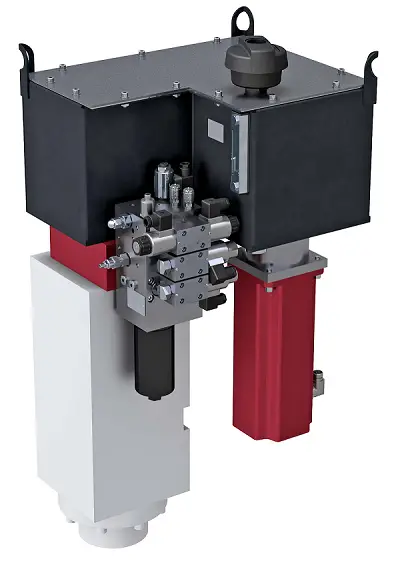
The central control block combines the three control blocks into one, and is mainly used in specialized structures for control purposes. The control block and the connection between the two hydraulic cylinders must be in a symmetrical arrangement.

It utilizes an SFA series of oil filling valves, which are designed in a flange structure and directly installed in the hydraulic cylinder, connected to the tank via a suction pipe.
Sensor and Axis Interface Distributor: All the solenoid valves are concentrated within a single control block and the electrical connections of the valves are also centralized into a single cable for easier connections. To achieve this, an interface distributor is provided on the central control block.

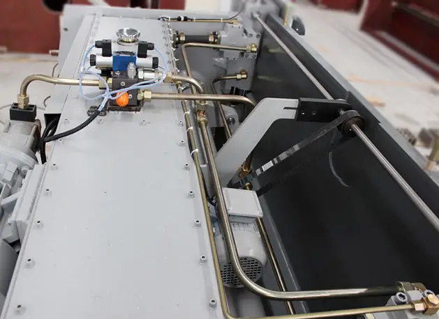
HYDRAULIC CYLINDERS (in hydraulic press brakes) in which a piston driven by a fluid (oil) under pressure from a pump moves the upper beam (or, rarely, the bench), generating the necessary force for bending. There are normally two cylinders that move on axes Y1 and Y2 and they must be perfectly parallel to avoid angle differences along the profile.
Further reading:
The hydraulic system requires that the hydraulic oil be kept clean. Cleaning the oil tank is crucial.
When replacing the hydraulic oil, the cover of the oil tank must be removed. Clean the bottom of the tank using a towel (do not use cotton yarn) and then wash it with cleaning coal oil gasoline.
Due to the limited reach of the arm to the end of the tank, a towel can be wrapped around a bamboo or stick to clean the corners. The leaking plug or brake valve should be loosened to allow the dirty oil to drain.
Use a cleaning towel to dry the sides and bottom of the tank until it is clean. If necessary, use a dough ball to pick up dirt at the welding seams or hard-to-reach areas and then put the cover back on.
Further reading:
Recommended hydraulic oil for press brake
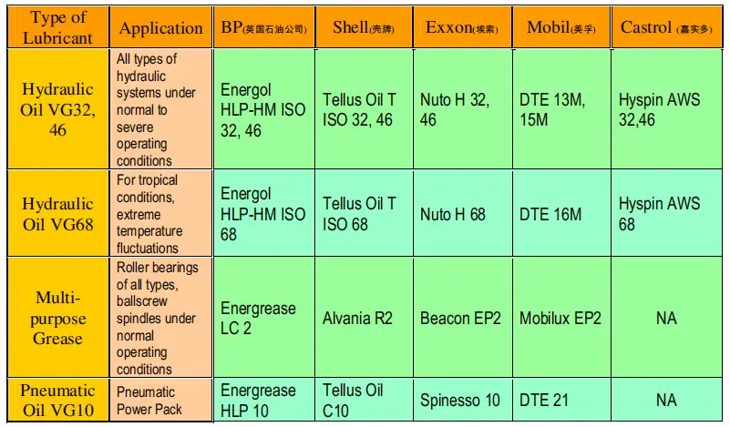
The mark value of hydraulic oil represents the average viscosity value at a temperature of 40°C. If the working pressure and temperature of the hydraulic system are higher and the working speeds are slower, a higher-marked hydraulic oil should be used.
It is recommended to use antiwear hydraulic oil ISO VG46# (with an average viscosity of 46mm2/s at 40°C). If the machine operates at temperatures below 5°C for an extended period, hydraulic oil ISO VG32# can be used.
It is not recommended to use the machine at very low temperatures (below -5°C). If this does occur, the machine should be allowed to idle for a while. If needed, an oil heater can be installed in the circuit.
Under normal working conditions, the oil temperature should not exceed 70°C. In special conditions, an oil cooler can be installed as necessary.
The hydraulic oil used must be clean. To fill the oil, unscrew the nut of the air filter and fill through the filter. If using filling equipment with a filter, the cover of the oil tank can be opened and the oil can be filled directly.
Observe the oil gauge and fill the oil to 80-90% of the interspaces when the ram stops at the top dead spot.
To ensure proper functioning, the machine should be run idle first, then at maximum stroke to eliminate any air bubbles in the hydraulic circuit.
NC press brake oil tank capacity chart
| Model | Oil Tank Capacity (L) |
|---|---|
| 30t/1600 | 65 |
| 30t/2000 | 65 |
| 40t/2500 | 130 |
| 63t/2500 | 140 |
| 63t/3200 | 150 |
| 80t/2500 | 130 |
| 80t/3200 | 165 |
| 100t/2500 | 230 |
| 100t/3200 | 230 |
| 100t/4000 | 250 |
| 125t/3200 | 220 |
| 125t/4000 | 250 |
| 160t/2500 | 260 |
| 160t/3200 | 260 |
| 160t/4000 | 285 |
| 160t/5000 | 290 |
| 160t/6000 | 300 |
| 200T/3200 | 470 |
| 200T/4000 | 550 |
| 200T/5000 | 550 |
| 200T/6000 | 550 |
| 250T/3200 | 470 |
| 250T/4000 | 540 |
| 250T/5000 | 550 |
| 250T/6000 | 560 |
| 300T/3200 | 540 |
| 300T/4000 | 540 |
| 300T/5000 | 550 |
| 300T/6000 | 560 |
| 400T/4000 | 540 |
| 400T/5000 | 550 |
| 400T/6000 | 550 |
| 500T/4000 | 560 |
| 500T/5000 | 560 |
| 500T/6000 | 620 |
| 500T/7000 | 620 |
| 600T/4000 | 650 |
| 600T/5000 | 650 |
| 600T/6000 | 650 |
| 600T/7000 | 650 |
CNC press brake oil tank capacity chart
| Model | SS Tank (L) | MS Tank (L) |
|---|---|---|
| 40T/1300 | 140 | 150 |
| 63T/1300 | 140 | 150 |
| 63T/2500 | 140 | 260 |
| 80T/2500 | 140 | 260 |
| 100T/3200 | 140 | 260 |
| 100T/4000 | 140 | 260 |
| 125T/3200 | 140 | 260 |
| 125T/4000 | 140 | 260 |
| 160T/3200 | 280 | 370 |
| 160T/4000 | 280 | 370 |
| 220T/3200 | 280 | 420 |
| 220T/4000 | 280 | 420 |
The oil seal is an important component of the press brake machine.


Goniometers can be mounted on the press brake table or directly onto tools thanks to the magnets with which they are equipped. They enable the operator to carry out bends with the sheet metal positioned at a preset angle.
The auxiliary mechanism is equipped with various functional components that can be selected according to the needs of the user, including a worktable compensation mechanism, a backgauge, a quick-release die clamping device, a material carrier, an oil temperature control system that can cool or heat the oil, a photoelectric protection device, a centralized lubrication system, and more.
Further reading:
The weight of the press brake machine can range from 5T to 300T, which largely depends on the size of the machine. For example, an 80T/2000mm press brake weighs approximately 6T, while a 2000T x 12000mm press brake weighs over 300T.

As the founder of MachineMFG, I have dedicated over a decade of my career to the metalworking industry. My extensive experience has allowed me to become an expert in the fields of sheet metal fabrication, machining, mechanical engineering, and machine tools for metals. I am constantly thinking, reading, and writing about these subjects, constantly striving to stay at the forefront of my field. Let my knowledge and expertise be an asset to your business.