Press Brake Operation Manual (Training PDF)
Attention all mechanics and engineering enthusiasts! Have you ever wondered about the ins and outs of operating a press brake machine? In this blog post, we'll dive into the world…
Ever wondered why your metal bends aren’t always perfect? The secret lies in press brake crowning, a technique that ensures precision and quality in metal fabrication. This article will reveal how different crowning methods can transform your bending results, enhancing accuracy and consistency. Dive in to uncover the key to flawless metalwork!
Press brake crowning may not be a term that is familiar to most people, but it is a crucial process that ensures the accuracy and straightness of the bending workpiece in metal fabrication.
When a sheet of metal is bent using a press brake, the deformation force is concentrated in the middle, causing the ram and the worktable to deform along with the upper and lower die.
This can result in unevenness along the length of the die edge, affecting the quality of the bending workpiece. To counteract this deformation, deflection compensation devices are designed, and press brake crowning is one such method.
In this process, the amount of deformation is matched to the actual work, thus compensating for the deformation (crowning) and improving the bending quality of the sheet material.
The article explores three types of press brake crowning methods – geometric crowning, hydraulic crowning, and mechanical crowning – and their advantages and disadvantages.
While each method has its benefits, it’s essential to understand which method is best suited for different types of press brakes.
If you’re interested in learning more about press brake crowning and how it can improve the accuracy and quality of your metal fabrication work, read on.
Crowning is a system that compensates for the deformation of the press brake
during bending. In fact, the elastic structure of the machine can cause a 0.15mm
variation on the Y axis in the middle of the ram in a 3m press brake.
To compensate for this deformation, crowning creates an opposite force so that, during bending, the press brake applies the same force along the entire metal sheet. In this way, bending problems, such as curved profiles, are avoided.

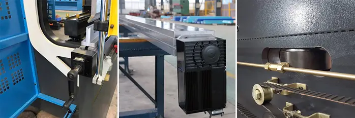
The press brake is pressurized by two working cylinders located at both ends of the ram. As a result, the deformation force of the bending workpiece is concentrated in the middle. Therefore, the ram and the worktable deform together with the upper and lower die.
This causes the sheet material to be uneven along the length of the die edge, which directly affects the accuracy and straightness of the bending workpiece. Therefore, it is necessary to take corresponding measures to reduce or eliminate the deflection caused by the deformation.
The deflection compensation device is designed to counteract this deformation. It is preset to deform in the direction opposite to the force-deformation in the ram and the upper die, or the worktable and the lower die working table. The amount of deformation should match the actual work, thus compensating for the deformation.
Therefore, to realize the compensation of the relative deformation of the ram to the worktable, the pressure distribution between the dies is more uniform and the bending quality of the sheet material is improved.
Moderm press brakes are sometimes equipped with automatic crowning systems, such as tables with wedges driven by a geared motor or tables with hydraulic cylinders with sensors connected to the CNC (this is called active crowning). In this instance, the sensors monitor pressure changes and immediately compensate for them to maintain the deformation.
The primary purpose of crowning in press brake operations is to provide flexibility in accommodating material variations and ensuring accurate and consistent bending. It helps to maintain a uniform force distribution across the bed and the ram, throughout the bending process. This minimizes the errors that can arise due to deflection and promotes better overall form.
In summary, crowning plays a crucial role in press brake operations by:
Crowning methods can vary from manual adjustments using an Allen key or digital readouts to motorized control systems, providing different levels of precision and automation in the process. Employing an effective crowning system is essential for press brake operators to achieve optimal bending accuracy, consistency, and efficiency in their work.
At present, the press brake crowning mainly has three types:
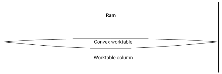
Generally, press brake manufacturers do not adopt this type of crowning method. The working table is fixed convex, meaning that during manufacture, the worktable is machined into an arc shape with a slight convex in the middle to compensate for the deflection caused by bending.
To make the appropriate correction for the upper mold, the middle part of the mold is slightly curved. So, when the slider undergoes upward deflection deformation, the upper die edge basically tends to be straight, therefore keeping each bending point along the bend line to generate the same bending force for the plate.
The advantages of the geometrical compensation method are low cost and ease of manufacture, but there are some disadvantages. It can only realize the compensation of fixed deformation and has small compensation flexibility. Additionally, the compensation block arc correction quantity needs to be calculated precisely.
The calculation method based on mechanics theory and finite element calculation has a certain error. Therefore, while this crowning method can achieve the deflection compensation effect, it is very difficult to realize.
Mainly used on electro-hydraulic synchronous CNC press brakes, hydraulic crowning is preferred since the compensation amount needs to be controlled by the controller such as DA52S, DA66T, and others.
Hydraulic crowning is achieved by installing two hydraulic cylinders on either side of the press brake frame, and another two auxiliary hydraulic cylinders in the middle of the machine. During the bending process, the auxiliary cylinder is filled with hydraulic oil and goes downward to generate downward deflection for compensation.
An automatic crowning system is formed by installing the auxiliary hydraulic cylinder in the lower part of the worktable, generating an upward force on the worktable during the bending process.
The pressure compensation device is composed of several small oil cylinders, a motherboard, an auxiliary plate, a pin shaft, and a compensating cylinder on the worktable, with a proportional relief valve forming the pressure compensation system. During operation, the auxiliary plate supports the oil cylinder, and the oil cylinder holds up the motherboard just enough to overcome the deformation of the ram and the worktable.
The convex device is controlled by a numerical control system, and the preload can be determined based on the thickness of the plate, the die opening, and the tensile strength of the material when bending different sheet materials.
Hydraulic crowning has the advantage of realizing deflection compensation for continuous variable deformation with large compensation flexibility. However, it also has some disadvantages of complex structure and relatively high cost.
The most widely used crowning method for the ordinary press brake is a good compensation method with low cost. In real operations, it is very convenient and easy for operators.
Mechanical crowning is a new deflection compensation method that generally uses a triangular oblique wedge structure. The principle is that two triangle wedge blocks with α angles are used, and the upper wedge moving is fixed at the X-direction and can only move in the Y-direction. When the wedge moves the △x distance along the X-direction, the upper wedge moves up the H distance under the lower wedge force.
Regarding the existing mechanical compensation structure, two bolster plates are placed in the full length on the worktable. The upper and lower plates are connected through the disc spring and bolts. The upper and lower plates consist of a number of oblique wedges with different slopes. The motor drives them to move relatively, forming an ideal curve for a set of convex positions.
The process of crowning involves compensating for the deformation of the press brake during bending. Crowning systems are essential in maintaining accuracy while working with a press brake. To set up the crowning system, operators need to input parameters such as sheet thickness, length, die opening, and material tensile strength into the machine’s control system. By analyzing these parameters, the control system automatically determines the real deflection of the table and ram, thereby obtaining the required preloading for each bend.
There are three common ways to perform crowning:
For manual crowning methods, shimming the die on the bed or adjusting the wedges is necessary to correct the alignment and maintain optimal bend accuracy. Programmable crowning systems, on the other hand, automate this process and eliminate potential errors.

The workpiece to be formed must be loaded onto the press brake and carefully aligned with the die. Before bending occurs, it is crucial to ensure that the workpiece is properly positioned, and any necessary adjustments have been made to the crowning system.
When the press brake is activated, the ram exerts force onto the workpiece, causing it to bend. The crowning system plays a critical role in compensating for any deformations that may occur during this process. As the workpiece is being formed, the crowning system ensures that the bending force is properly distributed along the entire length of the workpiece, resulting in precise and consistent bends.
To summarize, the process of crowning in press brakes involves setting up the crowning system, aligning the workpiece, and forming it with the help of the press brake’s ram. Achieving accurate and consistent bends relies heavily on a properly adjusted and functioning crowning system that compensates for any deformation during the bending process.
When the press brake machine is in operation, it will cause deformation, which is mainly due to the application of force at both ends of the machine. This force, generated during the bending process, causes deformation in the ram and the worktable, resulting in inconsistencies between the two ends of the workpiece and its central angle.
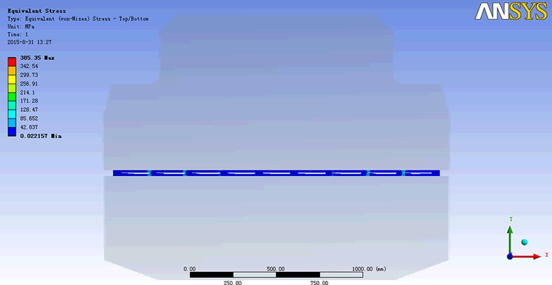
To analyze the press brake machine, the finite element method is widely used due to its speed and accuracy.
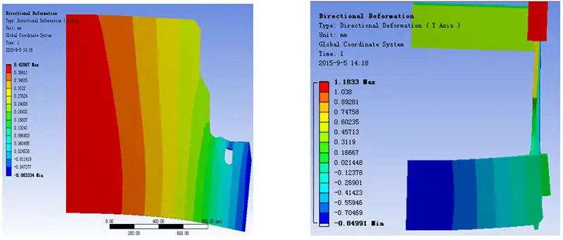
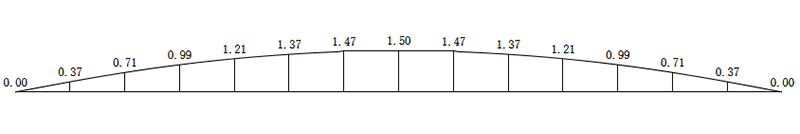
Convex curve of 100 ton 3-meter press brake machine obtained by finite element method:
There are several methods to compensate for deflection deformation:
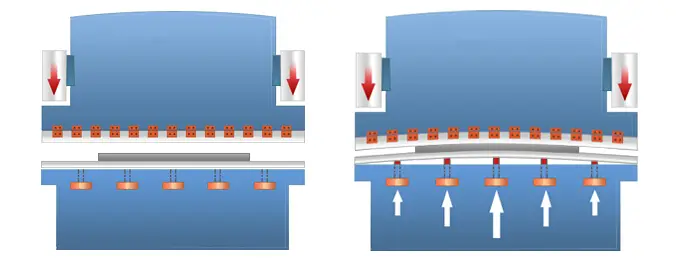
The worktable has a three-layer splint design, with compensating oil cylinders located throughout the structure.
When the system applies pressure to the compensating cylinders, it pushes up the middle splint of the three-layer splint, resulting in compensation for the deformation.

To control the position, compensation is provided at the corresponding point during bending to counteract the elastic deflection deformation of the machine.
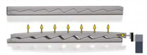
Mechanical compensation is achieved through a group of wedges with inclined planes, which can provide reverse compensation.

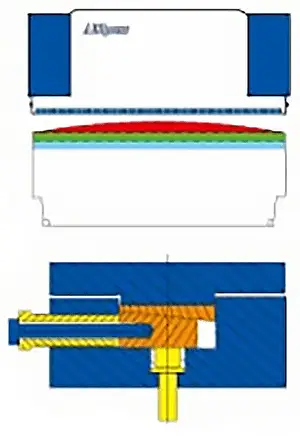
Before bending loading, pre convex state

After the bending is loaded, the actual compensation state is changed
Loading simulation animation of the convex worktable
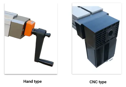
Driving mode
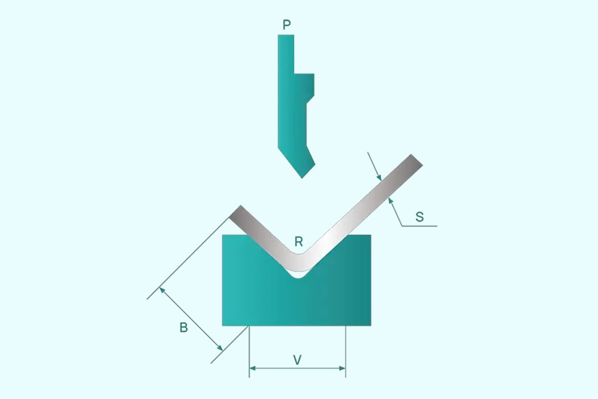
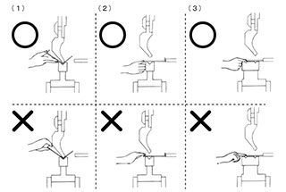
When it comes to bending workpieces, there are two key factors that determine its accuracy:
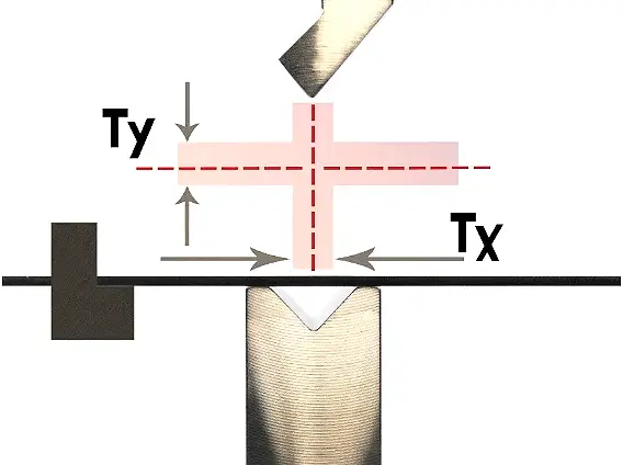
Fig. 1 Tx and Ty schematic
The greater the depth of the upper die of the press brake into the lower die, the smaller the bending angle.
Based on Figure 2, it can be calculated that when bending a 2mm carbon steel plate to 135° using the V12 lower die, a height direction deviation of 0.045mm can result in an angle deviation of 1.5°.

Fig. 2 Influence of height direction deviation on angle deviation
Further reading:
When a workpiece is bent using a press brake, the upper and lower beams may experience deflection and deformation due to their structural characteristics and the bending force applied, as illustrated in Figure 3.

Fig. 3 Deflection and deformation diagram of upper and lower beams
Currently, there is an inconsistency in the depth of the upper die entering the opening of the lower die along the full-length direction of the workpiece. This inconsistency can cause excessive deviation of the bending angle of the workpiece along its full-length direction.
This inconsistency typically results in a workpiece with a large middle angle and smaller angles at both ends, as depicted in Fig. 4.

Fig. 4 Schematic diagram of bending angle
Therefore, to ensure consistency of bending angle along the entire length of the workpiece, a crowning system needs to be introduced in the press brake.
As mentioned above, when the press brake bends the workpiece, the upper and lower beams, due to their structural characteristics, undergo deflection deformation under the bending force. This can lead to excessive deviation of the bending angle of the workpiece in the full-length direction.
However, the crowning system can effectively compensate for the deflection deformation of the press brake. By using the crowning system on either the upper or lower beam, the consistency of the bending angle can be ensured throughout the length of the workpiece.
The crowning system is divided into two categories:
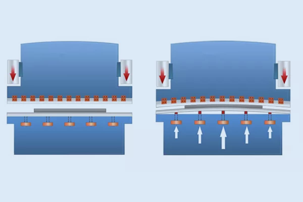
The hydraulic crowning system operates on the principle of embedding several hydraulic cylinders in the lower beam of the press brake. Each hydraulic cylinder can be controlled separately, causing the lower beam to form a certain bulge, as illustrated in Figure 1.
Theoretically, using more hydraulic cylinders increases the number of compensation points, resulting in higher compensation accuracy.
Hydraulic crowning is a discrete compensation method that is built-in.
To achieve a high-resolution compensation effect and high bending accuracy, the number of hydraulic cylinders and their hydraulic control system must meet higher requirements, resulting in a more complex overall structure and a higher cost of the press brake.
It is not possible to retrofit the hydraulic crowning system onto an existing customer press brake.
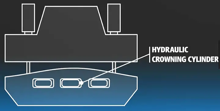
Fig. 1 Schematic diagram of hydraulic crowning system
The mechanical crowning system utilizes the filling method to compensate for the lower beam/lower die. Its main principle involves generating various compensation curves by means of the mutual movement of a pair of deflection compensation wedges, as demonstrated in Figure 2.

Fig. 2 Schematic diagram of mechanical crowning system
There are many types of mechanical crowning systems available in the market.
Let’s take the example of Wila’s mechanical compensation workbench. It falls under the category of external, relatively continuous compensation. This system can be directly installed on the lower beam of the press brake and is suitable for both new and old press brakes.
The compensation curves of this system can be adjusted continuously for various applications, as demonstrated in Fig. 3.
Further reading:
The length of a sheet metal bend greatly affects its bending accuracy. The longer the sheet metal, the greater the bending force required, leading to larger equipment inclinations and ram deformations, making accuracy harder to ensure. This bending accuracy, including the total bending length, is referred to as “straight line accuracy.”
Without effective measures, inconsistent amounts of concave die entering the full length direction of the bending upper die can cause the bending part to have a “boat belle” effect. To address this issue, a finite element simulation method was used to analyze the ram’s force and deformation displacement. The deflection compensation curve was extracted and modified, and combined with empirical data to design and manufacture a new mechanical deflection compensation device.
The linear accuracy of large-size press brake machines can be improved by using a driving motor or manual adjustment to compensate for deflection in the whole or part of the length.
Modeling
The press brake ram is made of steel plates of various shapes. During the modeling process, only the main structure of the ram is considered, while details that have little impact on the results are ignored. The main body dimensions are 8000mm x 2500mm x 120mm.
The elastic modulus is set to 2 x 10⁵ MPa, Poisson’s ratio to 0.27, and density to 7.8 x 10³ kg/m3. Given the structural characteristics of the ram, a solid95 element defined by 20 nodes was selected for the analysis.
This element has the capability to adapt to curved boundary models and accurately analyze the elastic deformation of the ram, as it has arbitrary 3D orientation.
(1) Constraints
In real-world conditions, the ram is always in motion. However, to perform a static analysis of the ram, it is necessary to simplify and approximate the constraints of the ram. To do this, symmetrical constraints are imposed on the nodes located on the middle symmetry plane of the ram.
The ram is fixed by connecting the guide rail on the frame to its back, where a full constraint is applied. This ensures that the ram remains in a fixed position during the analysis.
(2) Load condition
The surface load is applied to the contact area between the bottom of the hydraulic cylinder and the ram block. As the vertical deformation of the ram block is small compared to its total length, it is considered to be small elastic deformation. As a result, a uniform load is applied to the stress surface at the bottom of the ram block in the model.
To ensure that the force is evenly transmitted from the ram block to the upper die, the bottom of the ram block is connected to the upper die by a connecting block. This ensures that the load is distributed evenly and does not cause any imbalances in the system.
Extraction and analysis of simulation results
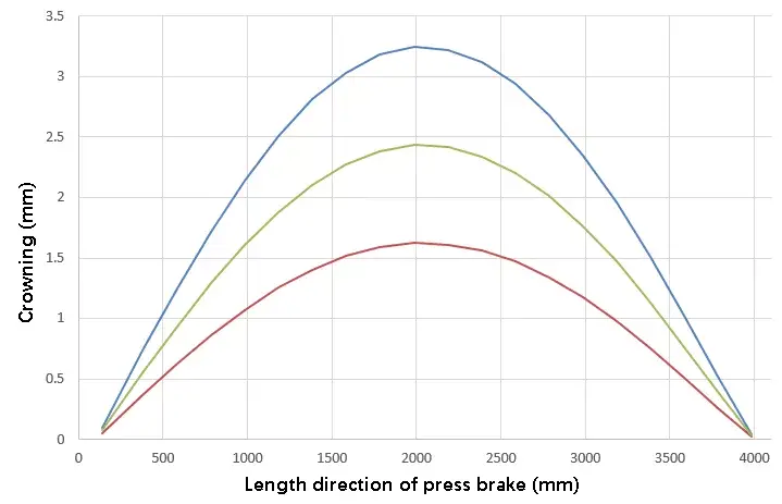
The displacement diagram of the ram block under load is shown in Figure 1. The path is set in ANSYS for result processing, and the deformation deflection curve of the stress surface at the bottom of the ram is extracted and shown in Figure 2.
As seen in the figure, the maximum displacement appears at the center of the ram and decreases gradually towards both sides in a parabolic shape. At the same time, the deformation displacement at any position along the bending length direction can be obtained, providing data support for designing wedges with different array angles to form the deflection curve.

The analysis shows that when a press brake machine is loaded, its stress surface on the ram produces parabolic deflection deformation due to its own structure, resulting in inconsistent bending angles of the workpiece along its full length. Additionally, local wear on the bending die also affects the straightness of the bent workpiece.
Currently, there are two common methods to address this issue. The first method is to install a hydraulic top cylinder at an appropriate position on the upper ram or lower worktable of the bending machine and control the ejection height of each top cylinder to compensate for the deformation. The second method is to use a mechanical deflection compensation device on the lower worktable, which compensates for deformation by adjusting the wedge blocks with different angles.
The hydraulic top cylinder method is easy to operate and meets the general accuracy requirements of bending production. However, for large-size and high-accuracy bending parts, the mechanical deflection compensation method is primarily used.
The traditional method for mechanical crowning involves manual adjustment of the compensation block or adding a gasket at worn areas, which is time-consuming, labor-intensive, and not very efficient, making it difficult to guarantee accuracy.
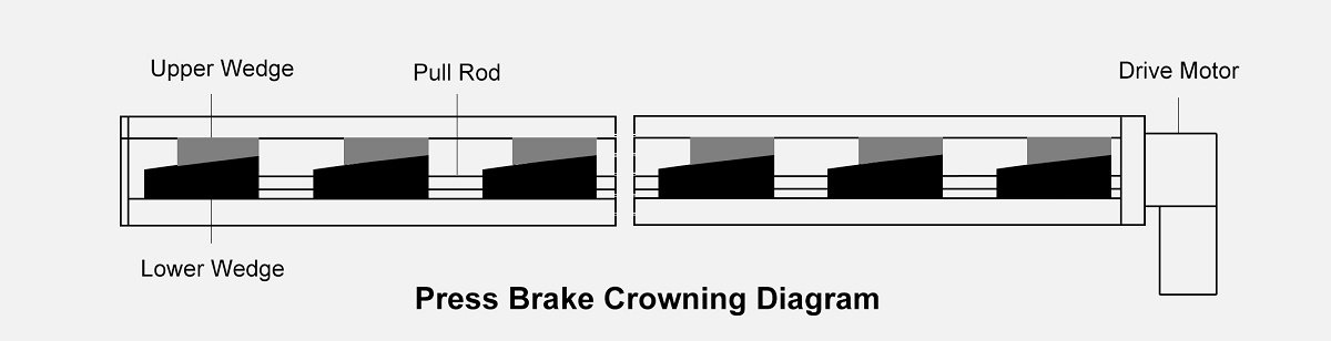
More advanced press brake machines, on the other hand, have automatic or semi-automatic deflection compensation mechanisms, such as the commonly used wedge type and pull rod type compensation devices. The wedge type device can ensure consistent angles and improve bending accuracy, but it requires a lot of manual labor and is not very efficient. The pull rod type device, on the other hand, easily compensates for deflection along the whole length, but it does not solve the issue of local wear.
Figure 3 (a) and (b) depict two types of deflection compensation devices.

Fig. 3 Common mechanical deflection compensation device
To address the issue of local wear, our mold company designed a four-piece wedge deflection compensation device. This device not only automatically compensates for the entire deflection of the workpiece, but also allows for manual adjustment to compensate for local wear of the die.
Figure 4 is a two-dimensional sectional view of the device, and its working principle is described as follows:

Fig. 4 Four piece wedge type deflection compensation device
(1) A rectangular groove is set along the length direction (i.e. longitudinally) on the base. In this groove, odd groups of wedge mechanisms are evenly distributed longitudinally. Each group consists of two pairs of four wedges, i.e. Wedge I, Wedge II, Wedge III, and Wedge IV, stacked from bottom to top.
(2) In each group of wedges, the lower pair, Wedge I and Wedge II, form a local adjusting mechanism. The inclined planes of each pair are matched correspondingly and arranged in a transverse direction.
Screw holes are set in the middle of the front and rear seat walls of the base corresponding to the big end of Wedge I. Adjusting bolts are installed on the outside of the base wall and each one extends into the base to connect with Wedge I.
To achieve local compensation, the bolt can be adjusted manually to move Wedge I forward and backward (transversely), thereby adjusting the upper cover plate and causing the worktable to move up and down.
(3) The upper pair, Wedge III and Wedge IV, form an integral adjusting mechanism. They are set longitudinally in each group and form an integral adjusting inclined wedge device.
Each pair of Wedges III are matched with the inclined plane of Wedges IV, with the largest inclination located in the middle of the rectangular groove on the base. The inclination gradually decreases towards the left and right sides of the groove. When the Wedges III move equidistantly along the length direction, the middle lift is substantial, forming a curve that adjusts the deflection based on the movement of the Wedges. This realizes the overall deflection compensation.
The short axis of each Wedge IV is symmetrically arranged on the front and rear side walls. A vertical notch groove is arranged on the upper part of the front and rear side walls of the rectangular groove of the base, corresponding to the short axis. The short axis of each Wedge IV slides in each notch groove, allowing only up and down movement and ensuring the lifting effect of Wedge IV.
(4) Longitudinal screw holes are set on Wedge III at the right end, while longitudinal through holes with the same center line as the screw holes are set on the other Wedge III. A hollow spacer sleeve is installed between each pair of adjacent Wedge III. A pull rod is installed in each Wedge III and hollow spacer sleeve. The right end of the pull rod is threaded into the Wedge III at the right end. An adjusting screw is installed at the right part of the screw hole of the Wedge III at the right end, and a motor is installed at the end of the adjusting screw to start the motor, which can achieve automatic overall deflection compensation.
Figure 5 shows an 8-meter-long device for double pull rod four-piece wedge deflection compensation.

Fig. 5 8m double strut wedge type deflection compensation device
Wrap it up
In this post, the small elastic deformation of the ram in a press brake machine is simulated and analyzed, and the deflection deformation data of the stress surface at the bottom of the ram is extracted.
Based on the experience data, a four-piece wedge deflection compensation device has been designed. It not only automatically adjusts the overall deflection compensation of the processed parts but also allows for manual adjustment of local die wear compensation.
The device has a well-designed structure, is convenient and reliable to use, improves the quality and production efficiency of sheet metal bending parts, and provides a new solution for large precision bending compensation.

As the founder of MachineMFG, I have dedicated over a decade of my career to the metalworking industry. My extensive experience has allowed me to become an expert in the fields of sheet metal fabrication, machining, mechanical engineering, and machine tools for metals. I am constantly thinking, reading, and writing about these subjects, constantly striving to stay at the forefront of my field. Let my knowledge and expertise be an asset to your business.