Deformation of Large CNC Press Brake Ram Solutions
Why do CNC press brake rams deform, causing costly production delays? This article explores the common causes of ram deformation in CNC press brakes, from prolonged usage to material stresses,…
Ever struggled with achieving precision and efficiency while using a CNC press brake? This article dives into practical tips to optimize your CNC press brake operations, covering everything from adding auxiliary tooling to refining die usage and improving bending techniques. By reading this, you’ll discover how to enhance processing capabilities, reduce setup time, and boost production quality, ultimately streamlining your metalworking processes. Whether you’re a seasoned operator or new to CNC press brakes, these insights will help you get the most out of your equipment.
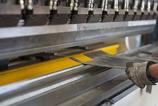
The press brake is primarily utilized for bending sheets of metal in a straight line. The sheet metal can be molded into various geometric shapes through the use of a simple die and processing equipment, as well as through stretching, stamping, punching, and corrugated pressing.
In practical production, the press brake is mainly employed for bending metal cabinets, boxes, U-beams, and rectangles with diverse geometric shapes. This process boasts several advantages, such as high bending straightness, absence of tooth marks, no peeling, and no wrinkles.
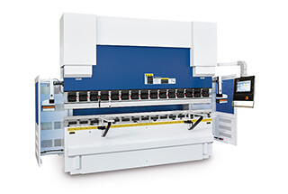
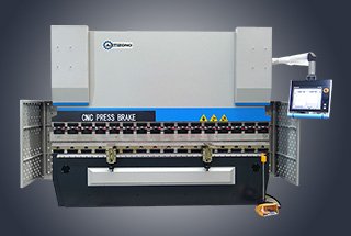
With the continued advancement of CNC press brake manufacturing technology, it has become increasingly popular among sheet metal manufacturing companies due to its high positioning accuracy, convenience, flexible disturbance compensation, and consistent processed products.
However, optimizing the utilization of the press brake to maximize its functions and benefits remains a pressing issue for CNC press brake manufacturers in limited circumstances.
Over time, we have effectively expanded the press brake’s functionality and accumulated experience through the addition of auxiliary tooling and modification of existing dies, as well as through flexible application on the job site.
This article, using the AMADA HFT170 numerical control press brake as an example, provides a comprehensive guide to its usage and techniques.
To use the machine tool with flexibility and ease, it is essential to incorporate auxiliary tooling. The addition of auxiliary tooling not only expands the processing capabilities of the machine but also enhances its processing efficiency.
The opening height of a press brake refers to the distance between the upper and lower worktables. The numerical control press brake HFT170 features a large opening height, which allows for an expanded processing range.
As illustrated in Figure 1, the addition of a transition plate to the original one can increase the bending height of the side of the component by 85 mm, enabling deep bending processing with a higher bending edge.
The width of the custom-made transition plate can be adjusted to fit the size of commonly used parts, making it ideal for small width components with high bending edges on both sides.
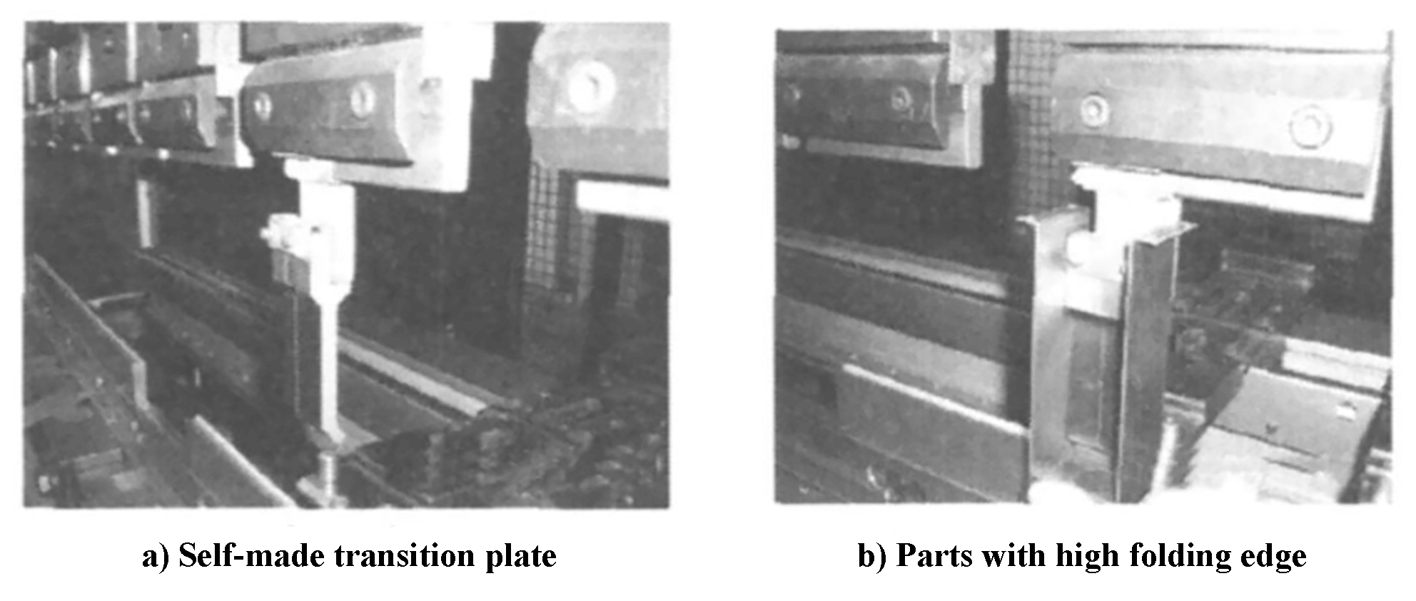
Fig. 1 Self-made transition plate and parts with high folding edge
As demonstrated in Figure 2, a bench angle has been installed in front of the machine to hold small parts, reducing the time required to retrieve them. Additionally, a small worktable has been added to facilitate the processing and collection of small workpieces.
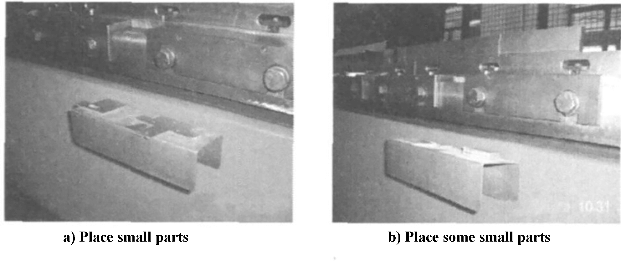
Fig. 2 Front bench angle
The effectiveness of a press brake largely depends on the upper and lower dies. If the number of dies is limited, the processing range of the machine tool becomes severely restricted.
Therefore, within fixed conditions, optimizing the combination and localized transformation of existing dies to maximize their function is a challenge that all machine tool users must consider.
The following section will provide an introduction on how to expand the function of a CNC press brake through die changes.
1) Tip of upper die R
Over time, the tip of the upper die may wear unevenly, causing changes in its height and impacting bending accuracy. To address this issue, the tip of the die can be ground and corrected to have a consistent R shape, in combination with a large V-shaped groove. This allows for the folding of thick plates, extending the service life of the die.
2) Change scrapped die to realize leveling
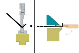
If there is no compound bending die, the problem of forming the pressed dead edge needs to be addressed. The pressed dead edge is a bending shape with two overlapping layers, commonly used for reinforcement. This type of edge is rare on plates with a diameter larger than 2.0 mm.
Typically, the pressing dead edge is formed through a compound bending die that requires at least two processes. Figure 3 illustrates the common method of using a compound bending die. In the first step, the material is bent at a 30° angle, and in the second step, the 30° bend is placed at the front of the compound die and further pressed into the pressed dead edge shape.
However, in this case, there is no compound bending die available. The only die that exists is a 30° acute bending die. The first step of the compound bending process can be achieved using this die. However, the second step requires an alternate solution.
One solution for the second step is to use the upper and lower parts of the die as the upper and lower planes. The upper die needs to be flattened, which can be achieved by removing the existing scrap upper die and grinding the knife edge into a flat style. This will solve the problem of forming the pressed dead edge.

Fig. 3 Hemming & flattening process
The modified die can be flattened for use. However, during the actual processing, machine operators may sometimes make mistakes such as reversing the bending edge or having unequal bending sizes. Unfortunately, when the surface requirements of the parts are not high, the parts may have to be scrapped.
Although it is possible to flatten only the bending edge, it is difficult to do so. However, using the combination of the upper and lower dies makes it easier to achieve a flat surface. By pressing the parts manually onto the upper and lower dies and using a CNC press brake, the parts can be flattened efficiently.
1) Bending material placement and die processing
When planning, the following factors should be considered to minimize the time and frequency of replacing the die:
a. Grouping materials of the same thickness;
b. Arranging dies of the same type together;
c. Placing dies with similar shapes together.
By following these guidelines, the time and effort required for die replacement can be reduced.
2) Right angle positioning of narrow and small parts
Positioning can be challenging when the bending part is narrow and long. During the process, it is common to use a gauge for positioning, but this can result in the bending part tilting. To address this, the method shown in Figure 4 can be employed. In this method, the die is firmly attached to the lower die to ensure a right angle and prevent tilting during bending.
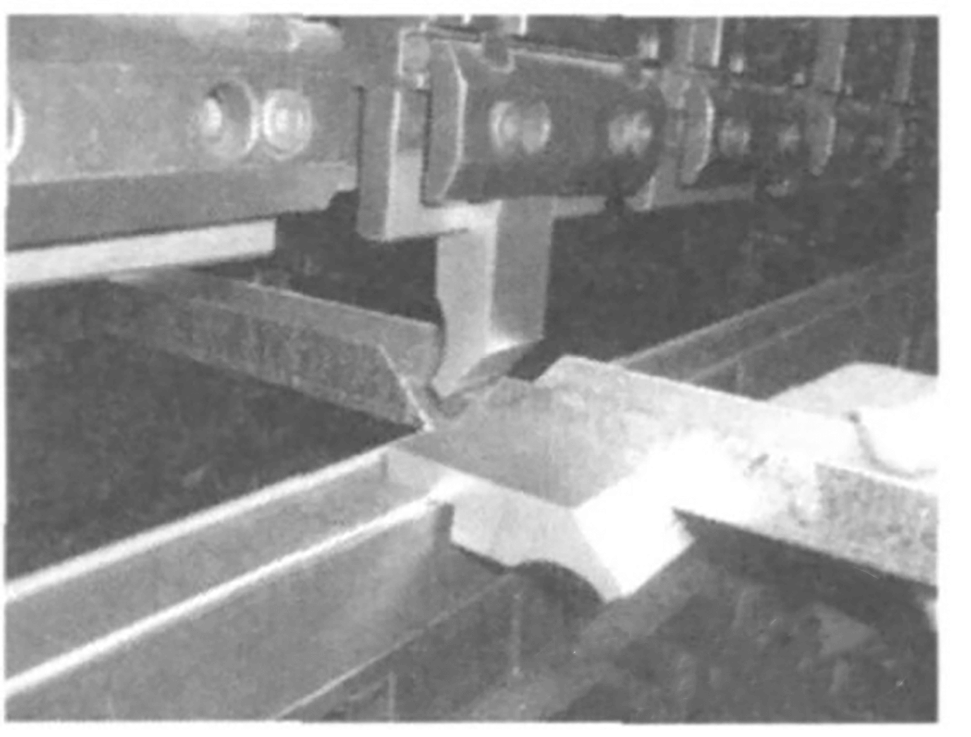
Fig. 4 Positioning processing method of right angle in narrow parts
3) Triangle parts bending
Bending sharp-edged parts can be difficult to bring close to the back of the gauge. The minimum size L is typically less than or equal to 10 mm, immediately after the fixed gauge, and requires the use of positioning devices. Neglecting this design and process step during actual work can often result in such problems.
The choice of bending die depends on the size of the parts. A single-part die is used for small parts, while a parallel pair die is used for double parts.
4) Add sheet R
Customers may have different requirements for the R value on the same bending edge. During the machining process, for parts that do not require high dimensional accuracy, the base plate can be used to increase the R value to meet the required specifications after bending.
To determine the required R value, the thickness of the plate is selected based on the relationship between V and inner R and is then bent into the shape shown in Figure 5. During use, the upper die is clamped using a clamp. This method is user-friendly and can be applied to multiple layers.
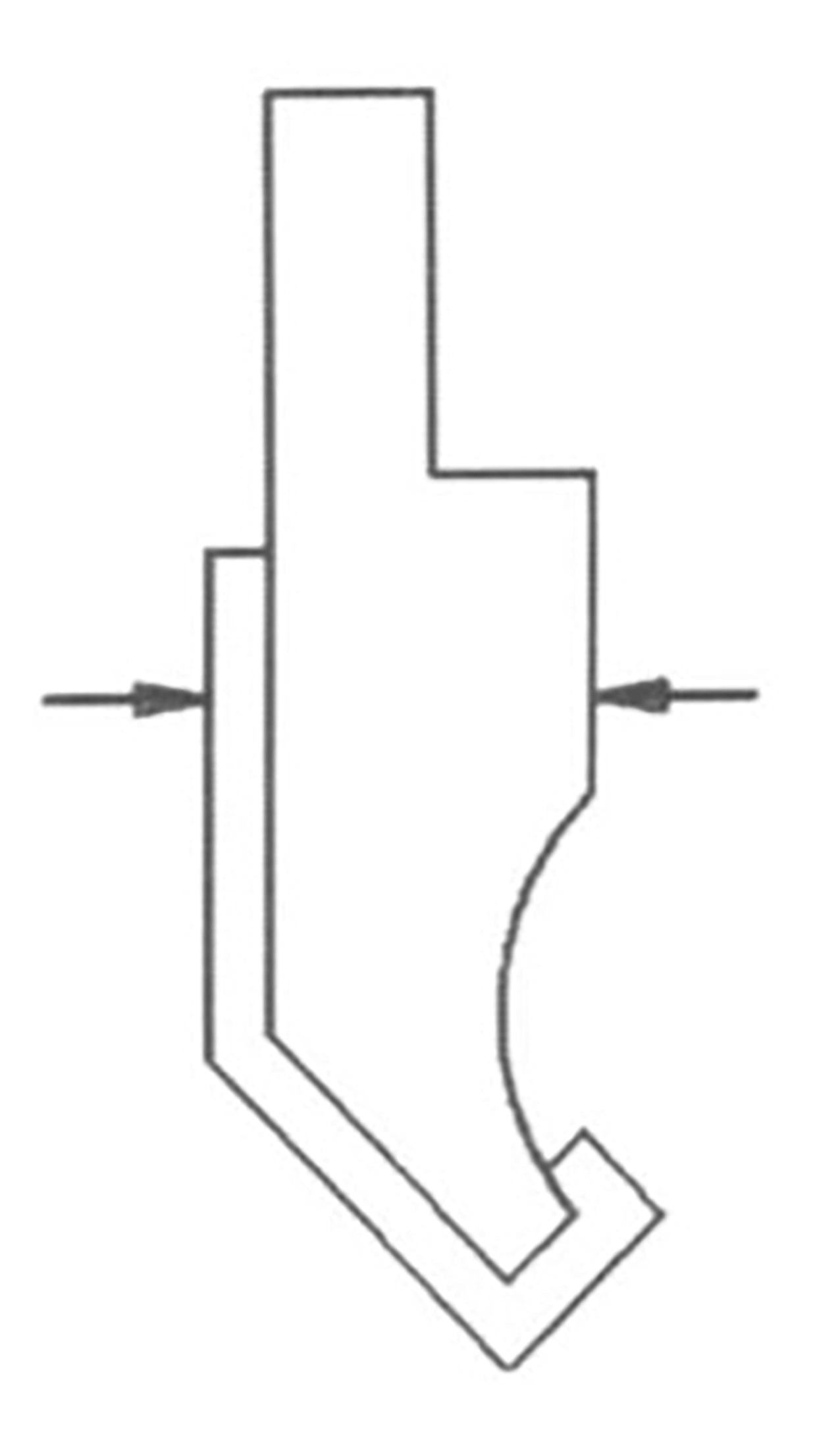
Fig.5 Folded shape
5) Single part with multi-die setting
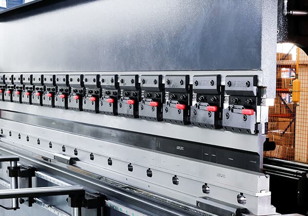
We utilize the HFTI70 press brake with two hydraulic cylinders and employ the multi-die setting as depicted in Figure 6.
This setup allows us to install both the upper and lower dies of the same model simultaneously, enabling us to perform multiple bending processes on the entire part, thereby reducing the time required for die installation and repetitive handling of the parts.
Currently, the market has introduced equal height bending upper dies, where the height of the upper die is standardized.
Additionally, various mold shapes can be utilized on the same worktable, enabling us to segment and bend different dies, resulting in a single installation of dies and a single transportation of parts.
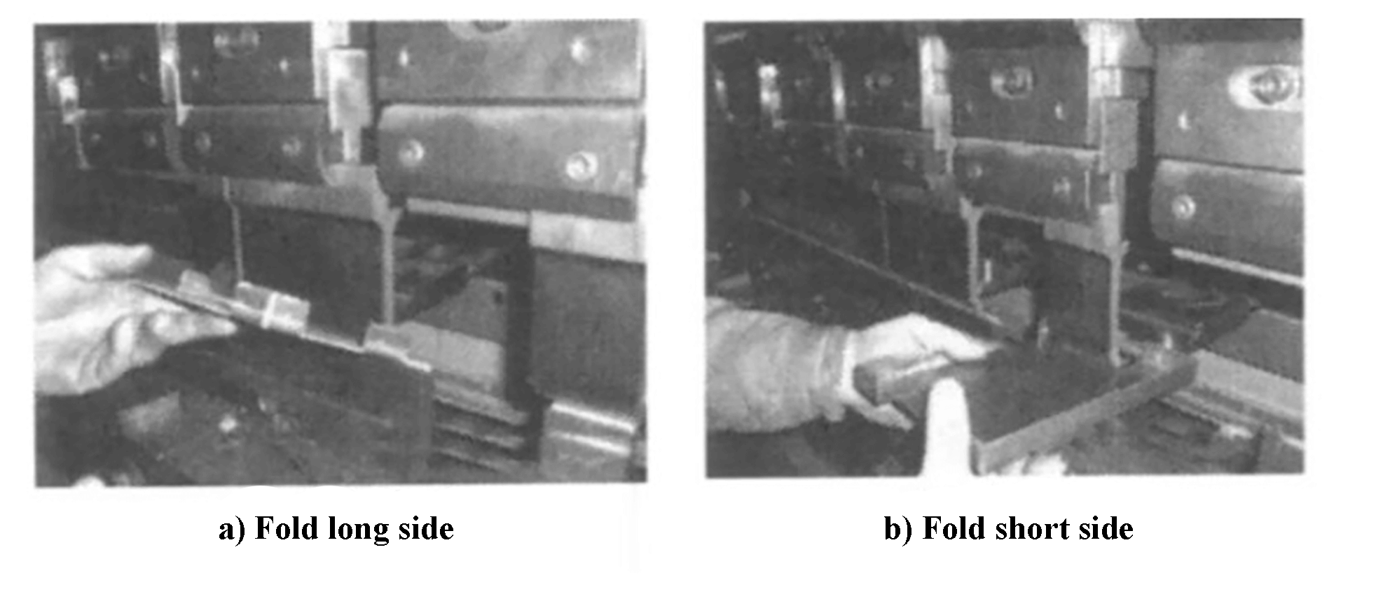
Fig. 6 Multi die setting
6) Program record of typical parts
After processing typical parts, it is important to record the processing parameters in a timely manner and store the program in the press brake’s storage area along with the part drawing number.
This way, the program can be easily reused in the future, significantly reducing the time required for preparatory work before bending.
We also maintain a table that contains detailed information such as the part name, drawing number, figure, material, and bending parameters.
The table is organized by material type, including steel plate, aluminum plate, and stainless steel plate, and each type is further differentiated by material thickness, making it easier to locate typical parts.
When combined with the process cards, this table serves as a comprehensive machining guide, allowing even inexperienced employees to follow the steps for processing parts.
7) The length of the die is not enough to bend in sections
In on-site processing, the length of the die is often shorter than the bending edge due to the use of specific dies that are designed for specific products.
When the length of the die is shorter than the bending edge, we use a segmented bending method.
At the point where the die length is close to the bending edge, it is perpendicular to the bend of the bending edge, and then the bending edge is folded into the desired size in segments.
Figure 7a illustrates the left-side bent part, and figure 7b depicts the right-side bent part.
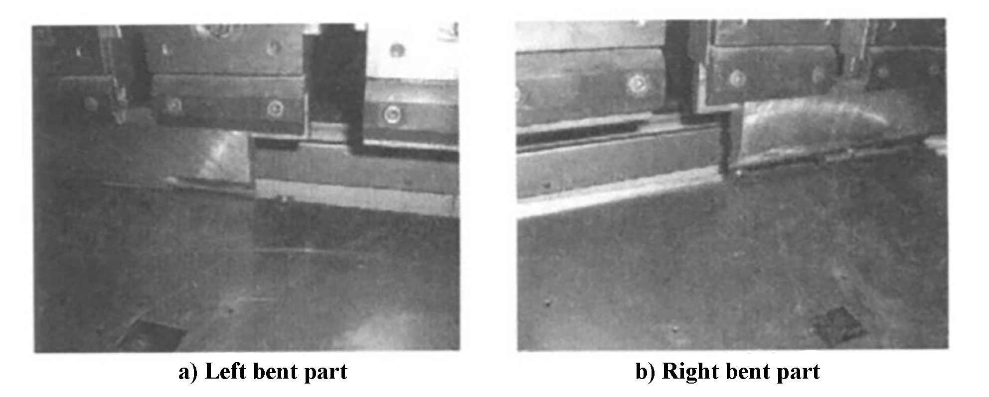
Fig. 7 Bending parts
8) Position with the stud on the back gauge
When the size of the bending part is large, it often results in the part sinking due to its weight and a short hand-held part, making it challenging for the operator to hold the workpiece in place.
To ensure the level of the parts, an operator must be stationed at the rear gauge to hold the parts in a horizontal position by hand. This requires two operators to be present during processing.
During the work, it was discovered that the back gauge can be lowered to a certain extent and the stud on the back gauge can be utilized for positioning.
By placing the parts horizontally on the back gauge, not only is the number of operators reduced, but the accuracy of the machining process is also effectively maintained.
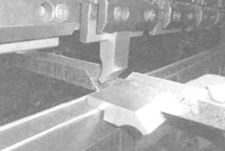
9) Bending of deep size closed shape parts
In actual processing, flexible use of deep-size closed shape parts can be achieved through bending.
Without the use of a closed deep bending die, when bending the parts as shown in Figure 7, we adopt the clamping state depicted in Figure 8 to separate the transition plates. The spacing is slightly larger than the width of the parts, allowing for the bending of two parts at a time with a reasonable size distribution.
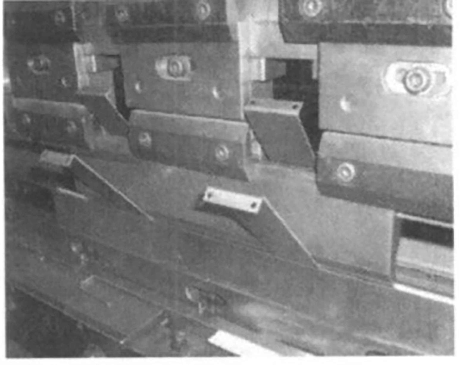
Fig. 8 Clamping status
The processing methods and techniques described above have effectively addressed the processing challenges faced in the production of a large number of similar parts in the company’s products.
They are highly suitable for the current trend of producing multiple varieties in small batches with a short production cycle.
Through years of production experience, these techniques have not only reduced tooling expenses but also shortened the production and processing cycle, lowering production costs and enhancing product quality.
These machining methods and techniques can also be applied to CNC press brakes with a similar structure.

As the founder of MachineMFG, I have dedicated over a decade of my career to the metalworking industry. My extensive experience has allowed me to become an expert in the fields of sheet metal fabrication, machining, mechanical engineering, and machine tools for metals. I am constantly thinking, reading, and writing about these subjects, constantly striving to stay at the forefront of my field. Let my knowledge and expertise be an asset to your business.