Ever wondered why robot laser cutting is revolutionizing manufacturing? This article explores how advanced programming methods and precision tools are enhancing accuracy in laser cutting. You’ll discover key factors affecting cutting precision and learn practical solutions to optimize performance. Dive in to understand how these technologies can streamline your operations and elevate product quality.
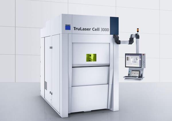
The laser cutting technology of series six axis robot and fiber laser can be used to trim and cut holes.
Compared with the traditional open die stamping technology, it shortens the process flow, greatly reduces the labor cost and mold cost, improves the product grade and added value, and is widely used in automobile manufacturing, aerospace industries.
This post mainly analyzes the main factors that affect the cutting accuracy of robot laser cutting machine after off-line programming and provides the corresponding solutions.
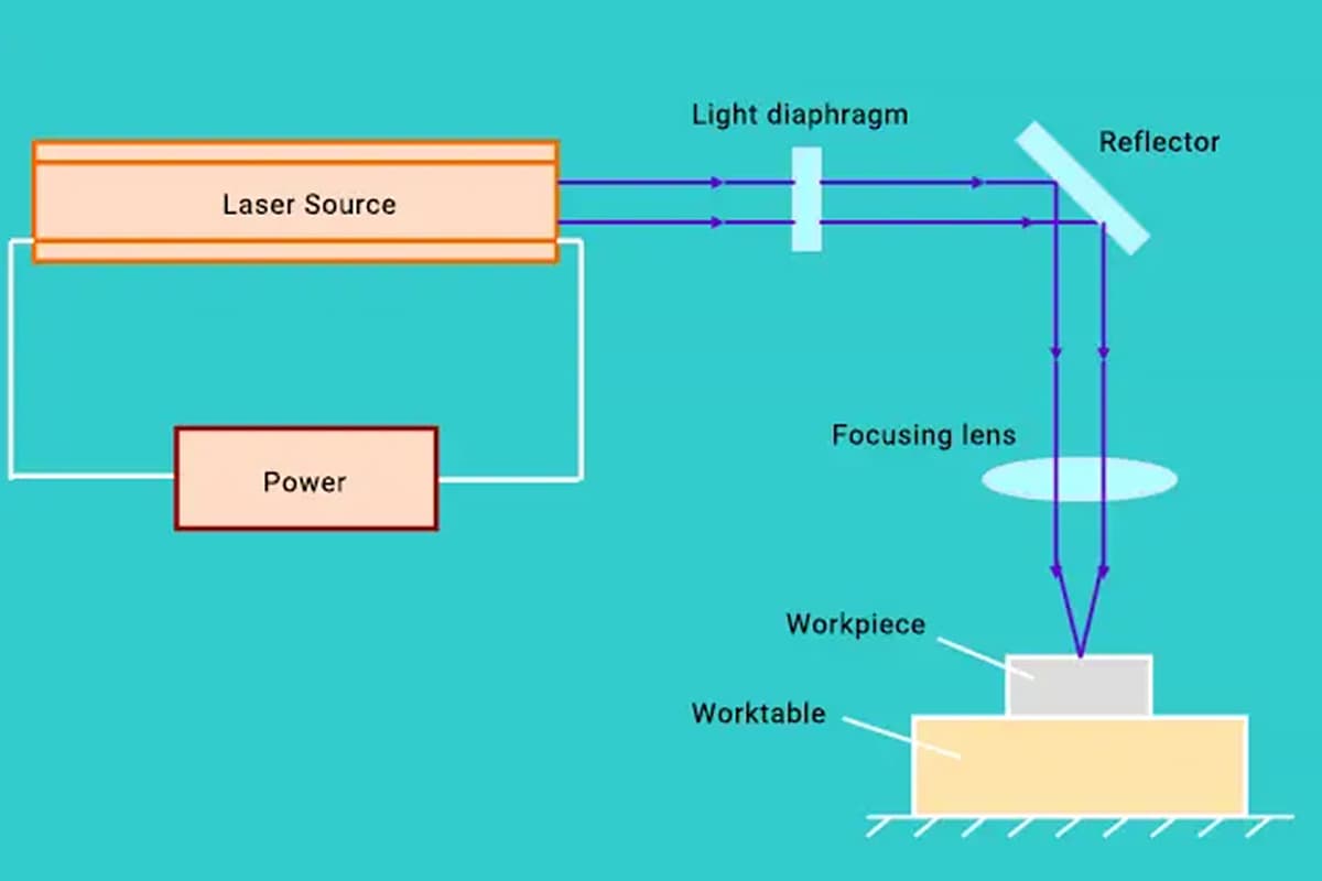
Programming mode of robot cutting machine
In recent years, the concept of industry 4.0 is deeply rooted in the hearts of the people, and the development of robot laser cutting machine towards intelligence has become a major trend.
If we want to develop and transform, we need to understand how the robot laser cutting machine completes the established work, and then we need to talk about its programming method.
Generally, the programming methods of serial robot laser cutting machine are mainly divided into teaching programming and off-line programming.
Teaching programming means that the operator’s “eye (observation) + brain (judgment) + hand (record)” will manually walk the end effector along the required track, and store it in the robot controller.
After the robot reads and learns, it will repeat these trajectories.
Its advantages are low threshold, easy to learn and can correct the error caused by mechanical structure.
However, the disadvantages are also obvious, the actual operating environment is needed.
The cutting quality depends on the operator’s experience, and it is not suitable for complex trajectory.
And the machine needs to stop production, which affecting productivity.
Off-line programming is to reconstruct the 3D virtual environment of the whole working scene in the computer through off-line simulation software.
Then, according to the size, shape and material of the parts to be processed, the software can automatically generate the trajectory of the robot with some operations of the software operator, that is, the control command.
Then the trajectory is simulated and adjusted in the software, and the robot program is generated and transmitted to the robot.
The advantage of this method is that it has the functions of trajectory simulation, path optimization and collision detection, and it doesn’t rely on the experience of the operator.
It can be far away from the actual operating environment, and is suitable for complex trajectories.
In addition, there is no need to stop production, improve production efficiency, and overcome many shortcomings of teaching programming.
Comparatively speaking, off-line programming is more suitable for the intelligent development direction of robot laser cutting machine.
However, many users use off-line programming, generally reflect that the cutting accuracy is poor.
Absolute positioning accuracy error of serial six axis robot
Offline programming needs to import simulation model into computer software.
The model represents the perfect design, and there are no geometric and kinematic errors in the simulation.
However, there are tolerances in the actual processing and assembly of robot parts, and there are also deviations between the encoder feedback value and the actual motion value in the motion process of the joint axis, which leads to errors between the actual position of the end effector and the theoretical target position when the robot executes the instructions given by the off-line programming.
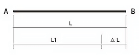
As shown in Figure 1, cutting a straight line from a to B, the offline programming software measures the theoretical length L between AB, and sends the command to the robot controller, but the robot’s own geometric size and motion error only walks L1 in actual execution, and there is a difference △L with the theoretical length, which is the absolute positioning accuracy error of the robot.
Fig. 1 absolute positioning difference △L
The series six axis robot generally has the characteristics of high repositioning accuracy (about 0.05mm) and extremely low absolute positioning accuracy (about 3mm difference per meter), which leads to worse geometric dimension accuracy when the robot adopts off-line programming.
Solution:
(1) modify the part model
For some parts with simple outline and low precision, cut a cuboid as shown in Figure 2.
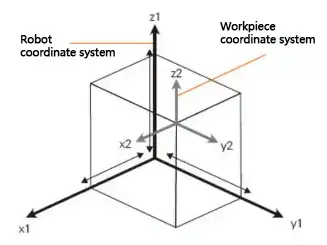
Firstly, the workpiece coordinate system is parallel to the robot coordinate system, then a solid sample is cut or marked according to the instructions generated by the normal part model, and the difference between the cutting dimension and the target dimension is measured along the workpiece coordinate system.
Then through the 3D modeling software or offline simulation software, the part model is enlarged or reduced along the workpiece coordinate system according to the difference, and the cutting program is regenerated to improve the dimensional accuracy.
Fig. 2 the model built when cutting a cuboid
(2) the laser tracker compensates the absolute positioning accuracy of the local area of the robot.
For parts with complex contour and high accuracy requirements, laser tracker can be used to compensate the accuracy of the robot end effector in the cutting area, as shown in Figure 3.
Fig. 3 laser tracker compensates the absolute positioning accuracy of the local area of robot
Using off-line programming to generate several spherical point positions from a known spherical model. The robot reads and executes.
The laser tracker captures and maps these points, and finally draws the actual spherical model by computer software.
After comparing with the known spherical model by offline programming, the absolute positioning accuracy of the robot in this area is calibrated and compensated.
Error of tool center point TCP
The end effector of the robot, also known as the tool, is installed on the end flange of the robot.
When we let the robot approach a certain point in space manually or programmatically, its essence is to let the tool center point approach the point.
Therefore, it can be said that the trajectory motion of the robot is the motion of the tool center point (TCP).
When the robot leaves the factory, it only knows the coordinates of the center point of the end flange, and the coordinates of the tool center point (TCP) need to be input into the robot controller after teaching.
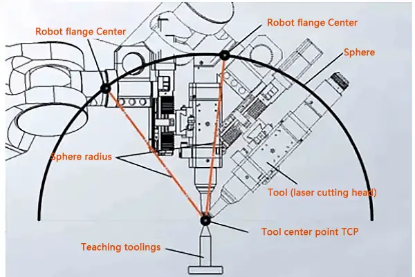
At present, the center point of the robot tool is generally calculated by four point drawing ball method, as shown in Figure 4.
Fig. 4 calculation tool center point TCP
That is to say, taking the center point of the tool as the center of the ball, drawing the sphere by collecting the center points of four different positions of the robot flange, and then calculating the coordinates of the center of the ball, which is the center point of the tool.
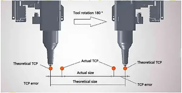
Since the position of the ball center is manually calibrated by observing the relative position of TCP and teaching fixture, there is an error between the center point of the tool calculated by this method and the center point of the actual tool, as shown in Figure 5, which is generally about 0.5mm.
Fig. 5 there is an error between the calculated tool center point and the actual tool center point
In the off-line programming software, there is no error in the tool center.
In the actual cutting of parts, as long as the laser cutting head rotates around the center of the tool, it will produce large size and position deviation.
Use infrared tool calibrator to calibrate tool center point
As shown in Figure 6, there are two orthogonal infrared transmitters and corresponding inductive switches in the circle of the tool calibrator.
Figure 6 TCP correction of tool center point with infrared tool calibrator
By performing a specific calibration procedure, the robot makes the tool move in the calibration circle.
When the robot tool blocks the infrared ray, the corresponding induction switch sends a signal to the robot controller, and finally the controller calculates and judges the position of the tool center point.
After calibration, the TCP accuracy of the tool center point can reach 0.1 mm.
Final thoughts
In addition to the above two main factors, the accuracy of robot laser cutting machine based on off-line programming is also related to the establishment of workpiece coordinate system, the attitude and load of robot, and the fitting degree of the part physical model.
However, the cutting accuracy errors caused by these factors are acceptable to most users, and can also be compensated by the operation experience of personnel to reduce these errors.
In short, in the near future, with the development and deep integration of vision technology, sensing technology, intelligent control, network and information technology, big data and other technologies, the off-line programming technology of robot laser cutting machine will be further developed to intelligence, such as automatic perception, identification and reconstruction of workpiece and processing path, realizing the independent path planning, automatic correction and adaptive environment.
With less and less human intervention, the user’s operation will be simpler and the cutting accuracy will be higher and higher.
As the founder of MachineMFG, I have dedicated over a decade of my career to the metalworking industry. My extensive experience has allowed me to become an expert in the fields of sheet metal fabrication, machining, mechanical engineering, and machine tools for metals. I am constantly thinking, reading, and writing about these subjects, constantly striving to stay at the forefront of my field. Let my knowledge and expertise be an asset to your business.
Are you curious about the cutting-edge technology revolutionizing manufacturing? In this blog post, we'll dive into the world of laser cutting machines, exploring their advantages and the top manufacturers dominating…
Have you ever wondered how a laser can cut through metal like a hot knife through butter? In this fascinating article, we'll explore the science behind fiber laser cutting technology.…
Why is laser cutting revolutionizing the shipbuilding industry? As shipbuilders face intense market competition and increased quality demands, laser cutting technology offers a solution with its high efficiency, precision, and…
Imagine cutting intricate car parts with the precision of a laser beam. Laser cutting technology is transforming the automotive industry, allowing manufacturers to create high-quality components with unmatched accuracy and…
Have you ever wondered how a laser cutting machine is set up for optimal performance? In this article, we’ll explore the essential steps for unpacking, inspecting, and installing your new…
Have you ever wondered how a powerful laser beam can cut through metal like a hot knife through butter? In this fascinating blog post, we'll explore the inner workings of…
Have you ever wondered how modern industries achieve such precise and efficient production? This article explores the world of fiber laser cutting machines, revealing their benefits and guiding you on…
This article explores the fascinating world of CO2 laser cutting technology, a game-changer in modern manufacturing. You'll learn how this method delivers unmatched precision and efficiency, transforming industries worldwide.
Imagine cutting intricate 3D shapes with the precision of a laser. This article dives into the latest advancements in 3D laser cutting machines, highlighting their flexibility, accuracy, and efficiency across…