Laser Cutting Nozzle Selection: Cutting-Edge Tips
Have you ever struggled with choosing the right laser cutting nozzle for your project? Selecting the optimal nozzle is crucial for achieving clean, precise cuts and maximizing efficiency. In this…
This article explores the fascinating world of CO2 laser cutting technology, a game-changer in modern manufacturing. You’ll learn how this method delivers unmatched precision and efficiency, transforming industries worldwide.
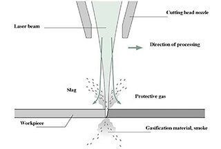
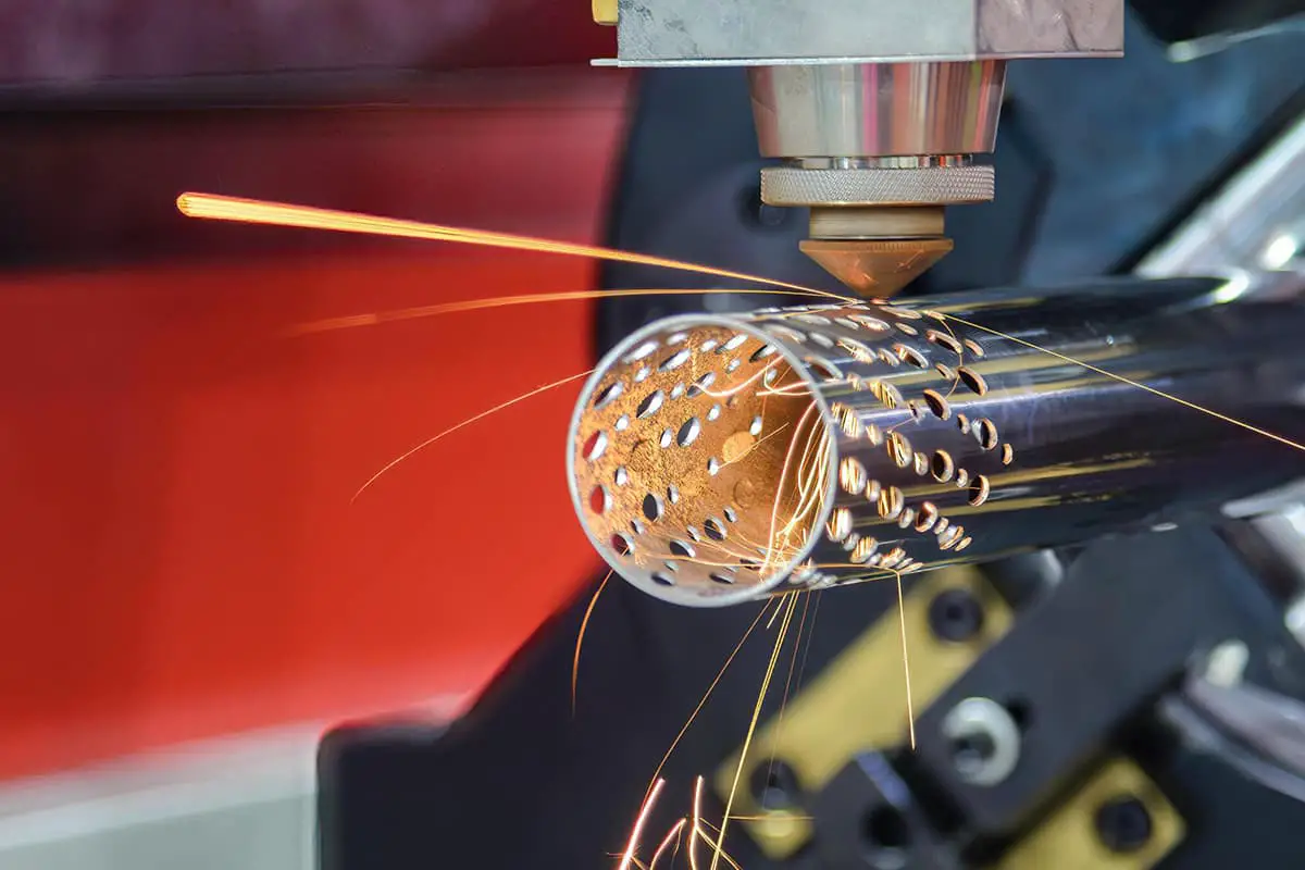
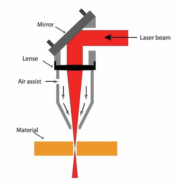
CO2 laser cutting employs a focusing lens to direct CO2 laser beams onto the material’s surface, causing it to melt.
Simultaneously, the melted material is removed by a coaxial flow of compressed gas, allowing the laser beams and material to move relative to each other along a defined path, resulting in a precise cut shape.
Since the 1970s, the development of CO2 lasers and numerical control technology has made CO2 laser cutting a highly advanced method for cutting plates.
In the 1950s and 1960s, plate cutting methods included:
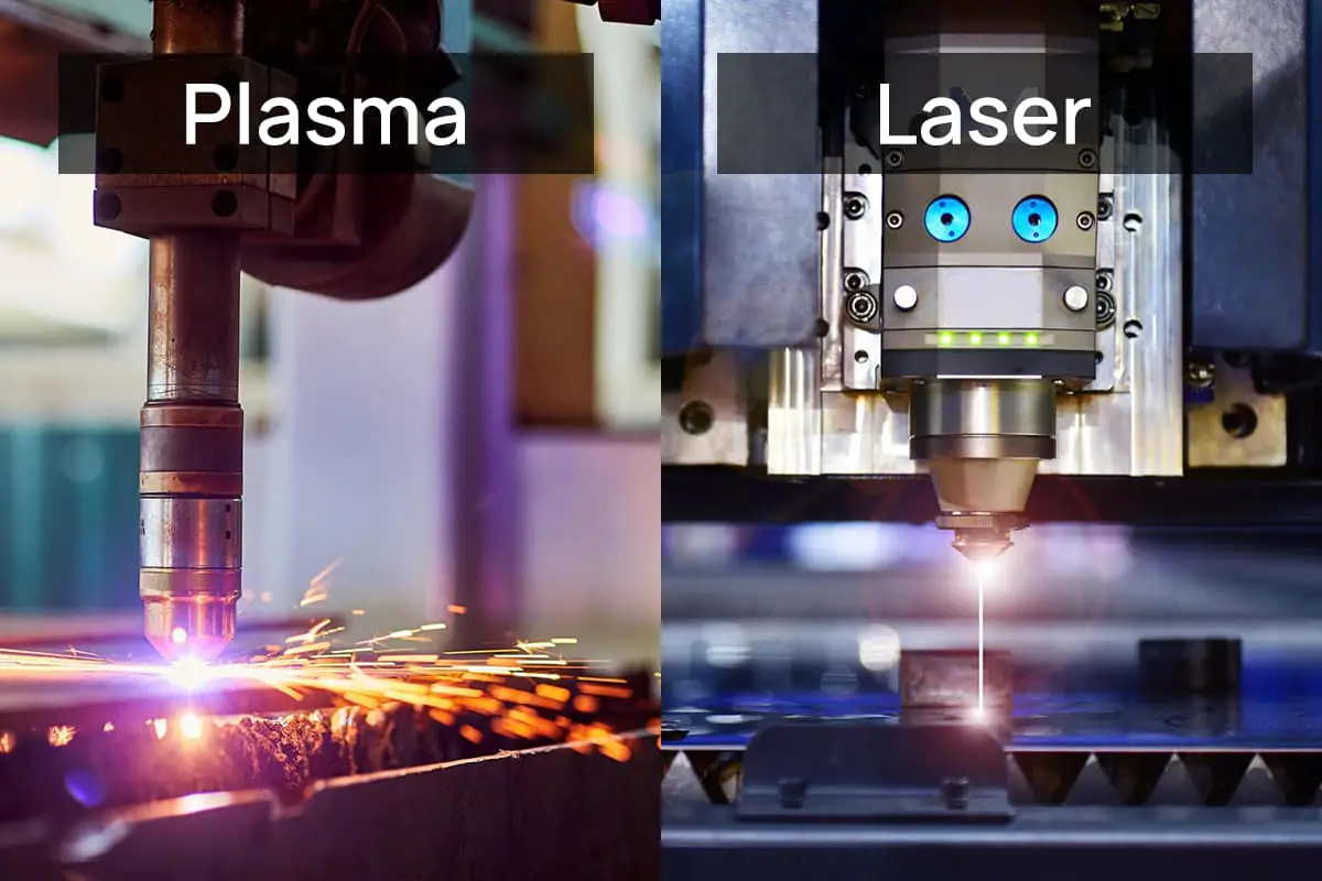
In the 1970s, to improve the quality of flame cuts, oxyethane precision flame cutting and plasma cutting became popular.
To reduce the manufacturing cycle time for large-scale stamping molds, CNC stamping and electroprocessing technology were promoted.
Each type of cutting and blanking method has its own limitations and is used in specific industrial production applications.
Good cutting quality:
High cutting speed:
For instance, a 2KW laser with a cutting speed of 1.6m/min can cut through 8mm thick carbon steel, while a cutting speed of 3.5m/min can be achieved for 2mm thick stainless steel. The laser cutting process results in a small thermal influence area and minimal deformation.
Clean, safe and non-pollution:
The use of CO2 laser cutting significantly improves the working environment for operators. While it may not surpass electro-processing in terms of precision and surface roughness of cuts, and may have limitations in cutting thickness compared to flame and plasma cutting, its advantages have led to its replacement of traditional cutting techniques, particularly for cutting non-metallic materials.
In China, since the 1990s and the development of the socialist market economy, there has been intense competition among enterprises, causing each company to carefully choose advanced manufacturing technologies that meet their specific needs in order to improve product quality and production efficiency. As a result, CO2 laser cutting technology has seen rapid growth in China.
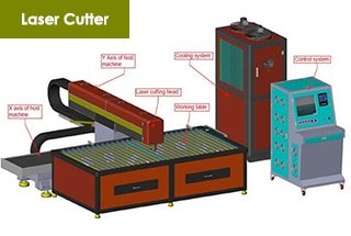
The first CO2 laser cutting machine was invented in the 1970s. Over the past three decades, the machine has undergone continuous improvement as its application fields expanded.
Currently, many international and domestic companies produce various types of CO2 laser cutting machines to meet market demand, including 2-D plate cutting machines, 3-D spatial curve cutting machines, and pipe cutting machines.
Prominent foreign companies in this field include Trumpf (Germany), Prima (Italy), Bystronic (Switzerland), Amada and MAZAK (Japan), NTC (Japan), and HG Laser Lab (Australia).
According to the 2000 Annual Report of “Industrial Laser Solution,” a leading American laser industry magazine, the total sales of laser cutting systems worldwide (primarily CO2 laser cutting systems) in 1999 were 3325, totaling $1.174 billion.
In China, nearly 100 CO2 laser cutting machines are produced each year, totaling 150 million RMB, but their usage in the country is relatively low compared to developed countries. By 2003, the number of CO2 laser cutting systems used in industrial production in China had reached around 500, accounting for approximately 1.5% of the world’s total.
There are two main types of organizations that utilize CO2 laser cutting technology: large and medium-sized manufacturing enterprises and processing stations.
Large and medium-sized manufacturing enterprises have strong economic and technical resources and require cutting and blanking for many of their materials.
Processing stations, also known as Job Shops abroad, specialize in providing laser processing services to others and do not have their own dominant products. These stations can meet the needs of small and medium-sized enterprises and also play a role in promoting the early adoption of laser cutting technology.
In 1999, there were 2,700 laser processing stations in the United States, with 51% of them specializing in laser cutting.
In the 1980s, laser processing stations in China primarily focused on laser heat treatment. However, since the 1990s, the number of laser cutting and processing stations has increased.
As reforms in China’s large and medium-sized enterprise system continue and the country’s economic strength grows, more and more enterprises are expected to adopt CO2 laser cutting technology.
Domestically, CO2 laser cutting is widely used for cutting low carbon steel plates with a thickness of 12mm or less, stainless steel plates with a thickness of 6mm or less, and non-metallic materials with a thickness of 20mm or less. It has also been used in the automobile and aviation industries for cutting three-dimensional spatial curves.
Currently, products suitable for CO2 laser cutting can be broadly categorized into three groups:
In addition to the aforementioned applications, CO2 laser cutting is being used in an increasing number of industries. For example, 3D laser cutting systems or industrial robots are used to cut spatial curves and specialized software has been developed to streamline the process from drawing to cutting parts.
Researchers are focused on improving production efficiency by developing specialized cutting systems, material conveying systems, and linear motor drive systems. Cutting speeds have now surpassed 100m/min.
In order to extend its use in the engineering machinery and shipbuilding industries, the cutting thickness for low-carbon steel has been increased to over 30mm, and there is growing interest in nitrogen gas low-carbon steel cutting technology to improve plate incision quality.
Thus, it is still very important for engineering technicians in China to expand the use of CO2 laser cutting and to address some technical problems in practical applications.
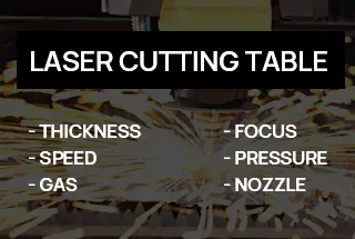
The laser beam parameters and the performance and precision of the machine and CNC system have a direct impact on the efficiency and quality of laser cutting. Key technologies such as those required for parts with high cutting accuracy or thicker materials must be mastered and solved.
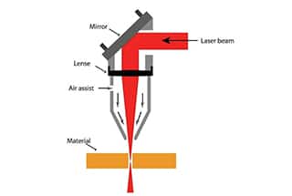
One of the benefits of laser cutting is the high energy density of the beams, which is generally greater than 10W/cm2. The energy density is inversely proportional to 4/πd^2, so the focal spot diameter is kept as small as possible to produce a narrow slit.
The focal spot diameter is directly proportional to the focal depth of the lens, meaning that the smaller the focal depth, the smaller the focal spot diameter. However, cutting can cause spatter and if the lens is too close to the workpiece, it can easily be damaged.
Therefore, high-power CO2 laser cutting typically uses lenses with a focal length of 5″ to 7.5″ (127 to 190mm). The actual focal spot diameter is between 0.1 and 0.4mm.
The effective focal depth also depends on the lens diameter and the material being cut. For example, when cutting carbon steel with a 5″ lens, the focal depth should be within a range of +2% of the focal length, or about 5mm, for optimal cutting quality.
To ensure the best cutting results, focusing is crucial and depends on the material’s thickness. For metal materials less than 6mm, the focus should be on the surface. For carbon steel thicker than 6mm, the focus should be above the surface. For stainless steel thicker than 6mm, the focus should be below the surface, but the exact size should be determined through experimentation.
Three simple methods for locating focus position in industrial production:
There are three methods to determine the focus of the CO2 laser cutting machine:
For flying light path cutting machines, the focus determination is more complex as the divergence angle of the laser beams causes differences in the distance between the near end and the distal end, leading to differences in the beam size before focusing. The larger the diameter of the incident beam, the smaller the focal spot.
To minimize the variation in focal spot size caused by changes in beam size before focusing, manufacturers of laser cutting systems have offered some special devices for users to choose from:
Laser cutting technology, except in a few cases, typically requires a small hole to be drilled on the material. In the past, laser stamping machines first used a punch to drill a hole, then used a laser to cut from the hole. For non-stamping laser cutting machines, there are two basic drilling methods:
For pulse drilling, the laser used should not only have high output power, but also high time and space characteristics of beams. The pulse drilling process should also have a reliable gas path control system to control the type of gas, gas pressure switching, and drilling time. The transition from pulse drilling to continuous cutting of the material should also be emphasized in order to achieve high-quality cuts.
In industrial production, it is more practical to change the average power of the laser, such as changing the pulse width, frequency, or both simultaneously. The third method has been shown to have the best effect.
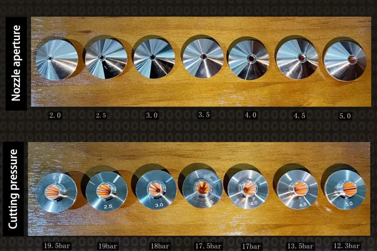
When cutting steel with a laser, oxygen and laser beam are aimed through a nozzle at the material to form a stream. For the cutting to be effective, the air flow needs to be large and fast to produce enough oxidation and exothermic reaction in the cut material. Additionally, the air flow must have enough momentum to remove the melted material. The design of the nozzle and the control of air flow, such as the pressure and position of the nozzle and the workpiece, are crucial factors that affect cutting quality.
Currently, nozzles used in laser cutting are simple in design, consisting of a cone with a small hole at the top. The design of the nozzle is usually done through experiments and derivation methods. However, since the nozzle is usually made of copper and is small and vulnerable, it requires frequent replacement and is not typically considered in fluid mechanics calculations and analysis.
When in use, gas with pressure Pn enters the nozzle and creates nozzle pressure. The gas sprays out from the nozzle and reaches the surface of the workpiece after a certain distance, forming cutting pressure Pc. Finally, the gas expands to form atmospheric pressure Pa. Research has shown that as Pn increases, the airflow velocity and Pc also increase.
The formula for calculating the airflow velocity is:
V = 8.2d^2 (Pg + 1)
where:
V = airflow velocity in L/min
d = nozzle diameter in mm
Pg = nozzle pressure (surface pressure) in bar
When the nozzle pressure exceeds a certain value, the airflow can transition from subsonic to supersonic and become a normal oblique shock wave. The threshold value depends on the ratio of nozzle pressure (Pn) to atmospheric pressure (Pa) and the degree of freedom (n) of the gas molecules. For example, when n=5 for oxygen and air, the threshold Pn is 1.89 bar.
If the nozzle pressure is higher, namely, Pn/Pa > 4 bar, the normal oblique shock wave of the airflow can change into a normal shock, causing the cutting pressure (Pc) to decrease, the air velocity to reduce, and a vortex to form on the workpiece surface, which weakens the effect of air flow in removing molten material and affects the cutting speed.
To avoid this, the nozzle pressure of oxygen is often kept below 3 bar when using a nozzle with a cone and a small hole at the top.
To enhance the speed of laser cutting, a convergent-divergent nozzle called the Laval nozzle has been designed based on aerodynamic principles. This nozzle increases pressure without causing normal shock waves. The structure of the nozzle is depicted in Figure 4 for ease of manufacturing.
The laser center at Hanover University in Germany conducted experiments by pairing a 500W CO2 laser (with a focal length of 2.5) with a cone hole nozzle and a Laval nozzle. The results of the experiments are depicted in figures, which show the relationship between surface roughness (Rz) and cutting speed (Vc) for No. 2, No. 4, and No. 5 nozzles under different oxygen pressures.
As shown in the figures, when the pressure (Pn) is 400 Kpa (or 4 bar), the cutting speed of the No. 2 hole nozzle only reaches 2.75 m/min (for a 2mm thick carbon steel plate). However, at Pn of 500 Kpa or 600 Kpa, the cutting speed of the No. 4 and No. 5 Laval nozzles reaches 3.5 m/min and 5.5 m/min, respectively.
It’s important to note that the cutting pressure (Pc) is dependent on the distance between the workpiece and the nozzle. The oblique shock wave is reflected repeatedly at the airflow boundary, causing the cutting pressure to fluctuate periodically.

The first high cutting pressure zone is located near the nozzle outlet, with the distance between the surface of the workpiece and the nozzle outlet being approximately 0.5 to 1.5mm. This results in high and stable cutting pressure (Pc), making it a widely used parameter in industrial production.
The second high cutting pressure zone is approximately 3 to 3.5mm away from the nozzle outlet and also exhibits high cutting pressure, contributing to good cutting results and protection of the lens, thereby improving its service life.
However, other high cutting pressure zones on the curves are too far from the nozzle outlet to align with the focused beam.
In conclusion, CO2 laser cutting technology is increasingly being utilized in China’s industrial production. Abroad, efforts are being made to study cutting technologies and equipment that can achieve higher cutting speeds and handle thicker steel plates.
To meet the growing demands for high-quality industrial production and increased efficiency, it is important to focus on solving key technological issues and implementing quality standards, making this new technology more widely adopted in our country.

As the founder of MachineMFG, I have dedicated over a decade of my career to the metalworking industry. My extensive experience has allowed me to become an expert in the fields of sheet metal fabrication, machining, mechanical engineering, and machine tools for metals. I am constantly thinking, reading, and writing about these subjects, constantly striving to stay at the forefront of my field. Let my knowledge and expertise be an asset to your business.