0° – 180° Bend Allowance Chart for Sheet Metal Bending
Have you ever wondered how sheet metal parts are designed and manufactured with precision? In this blog post, we'll dive into the fascinating world of bend allowance - a crucial…
Ever wondered how to precisely unfold sheet metal for bending? Understanding the K-factor is key. This article breaks down the calculation process, providing engineers and technicians with a practical guide to achieving accurate dimensions. Learn how theoretical analysis and 3D modeling software can transform your sheet metal projects, improving efficiency and precision. Get ready to enhance your metalworking skills and optimize your production process with these essential insights.

In recent years, the process of sheet metal bending has seen rapid development in the rail transit industry, as it is an essential processing method.
Accuracy in the dimensional aspects of the bending process is crucial for sheet metal processing companies, as bending is a comprehensive cold working process.
This post utilizes theoretical analysis of 90° bent sheet metal parts to deduce the method for calculating the K factor and explains the scope of its application. It provides engineers and technicians in the sheet metal industry with both a theoretical foundation and practical reference.
In the bending process, the outer layer of the sheet metal is subjected to tensile stress while the inner layer experiences compressive stress.
Between the outer and inner layers lies a transition layer known as the neutral layer, which experiences neither tensile nor compressive stress.
The length of the neutral layer remains constant before and after bending, making it an important factor in the calculation of the unfolding size of the sheet metal.
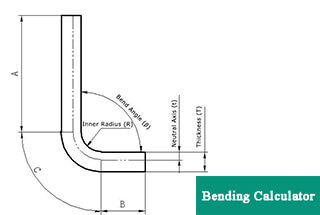
Figure 1 is a schematic illustration of the dimensions involved in sheet metal bending.
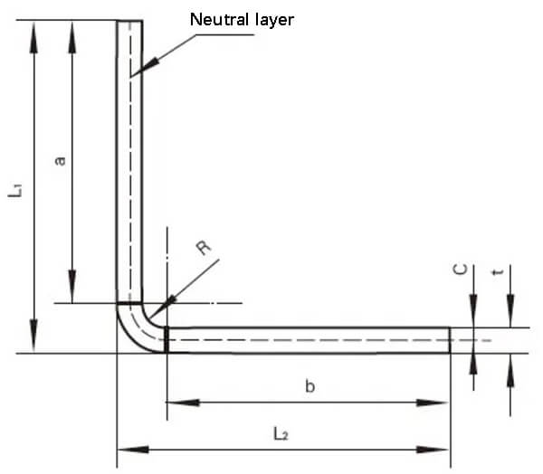
Fig. 1 Schematic diagram of sheet metal bending size
As shown in Fig. 1, the unfolding size of the sheet metal is set as L, so there is:
L=a+b+2π(R+C)/t ①
L1=a+R+t ②
L2=b+R+t ③
Where K factor: 0<K=c/t<1 ④
Derived from equations ① ~ ④, it can be obtained that:
K=2(L-L1-L2+2R+2t)/πt – R/t ⑤
The results obtained from equation ⑤ show that the value of the K factor is dependent on the overall dimensions, bending inner diameter, and material thickness of the sheet metal parts.
Traditionally, sheet metal technicians would create a CAD sheet metal unfolding drawing based on the bending coefficient derived from years of bending experience. They would then draw the unfolded sheet metal shape, export it in DXF format, and input it into a laser cutting machine to obtain the unfolding shape of the part.
In this traditional manual calculation method, the bending coefficient can vary between different processing facilities.
As an example, consider the back cover of a power cabinet for an electric locomotive, made of 1.5mm thick cold-rolled steel plate, as shown in Figure 2. One processing plant would calculate its expansion size as follows:
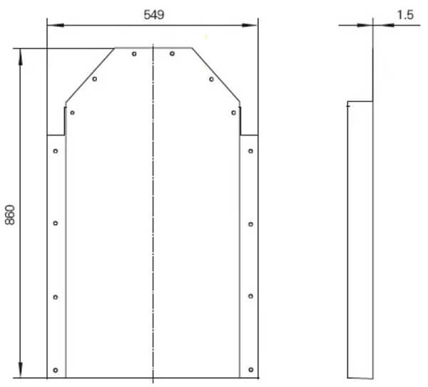
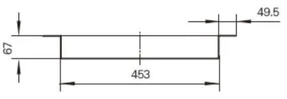
Fig. 2 Dimension diagram of rear cover of a power cabinet
Total width = 453 + 67 × 2+49.5 × 2-8 × 1.5 (material thickness) + 4 × 0.5 (bending factor) = 676mm
Total length = 860 + 67-2 × 1.5 (material thickness) + 0.5 (bending coefficient) = 924.5mm
The manual drawing process is low in efficiency.
By using a three-dimensional modeling software and the K-factor method, the efficiency of sheet metal unfolding calculation is significantly improved.
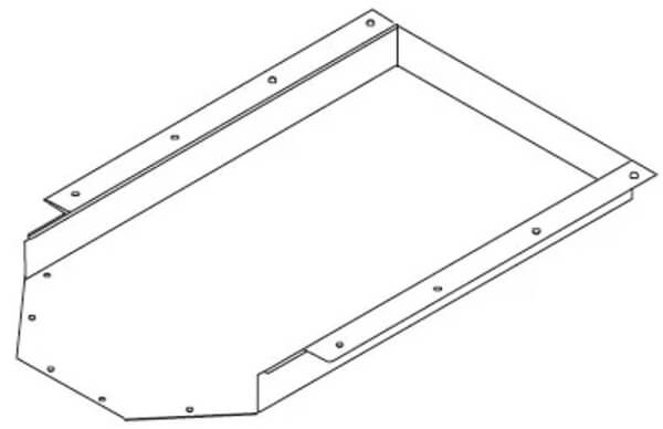
Fig. 3 3D view of the back cover of a power cabinet
By using the traditional manual method of calculating the unfolded size of sheet metal, the unfolded size and bending inner diameter are plugged into equation ⑤ to determine the corresponding K factor.
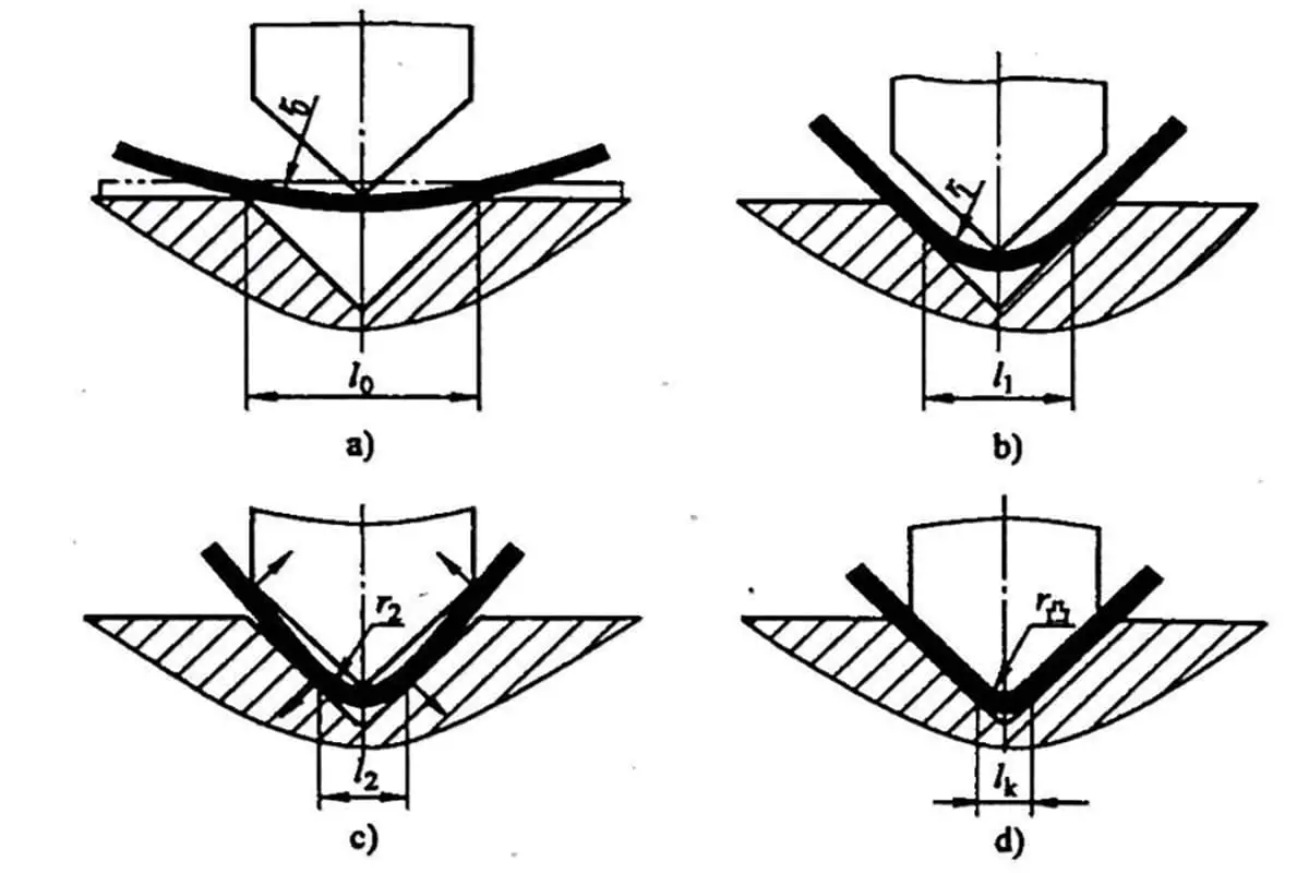
During the sheet metal bending process, a smaller bending inner diameter results in increased compression and tension on the inner and outer layers of the material. If the yield strength of the material is exceeded, cracks and fractures can occur.
For example, the rear cover of a power cabinet for an electric locomotive in Figure 2 has a bending inner diameter of 1.5mm, and the corresponding K factor calculated using equation ⑤ is 0.486 when using a three-dimensional modeling software.
Similarly, the K factor for other thickness specifications can be calculated.
Table 1 lists the bending parameters used by a sheet metal processing enterprise.
Table 1 SolidWorks bending parameters
| Material thickness (mm) | K factor | Bending inner diameter (mm) |
| 1.5 | 0.486 | 1.5 |
| 2 | 0.486 | 2 |
| 3 | 0.486 | 3 |
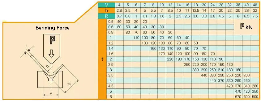
Fig. 4 Quick check table of the bending force of press brake machine
The K factor calculation result can be entered into the 3D modeling software.
However, when the software is used for direct expansion, there may be gaps in the expanded drawing, such as those seen in local enlarged drawings I and II in Figure 5.
These gaps must be corrected to meet the requirements for laser cutting, as demonstrated in Figure 6.
The 3D modeling software can also export DXF drawings with bending lines to aid in subsequent bending processes.
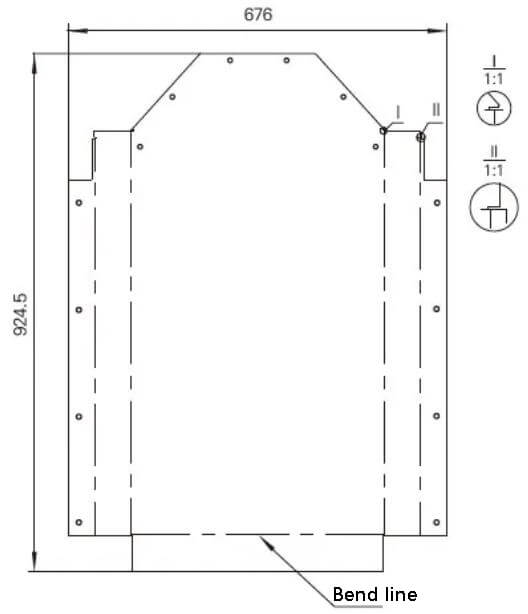
Fig. 5 Expanded view of the rear cover of power cabinet directly exported by 3D modeling software
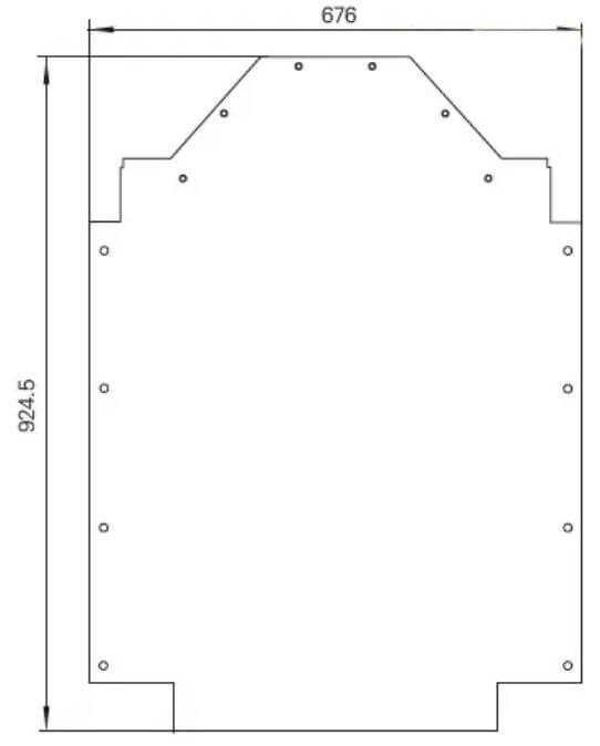
Fig. 6 Modified expanded view
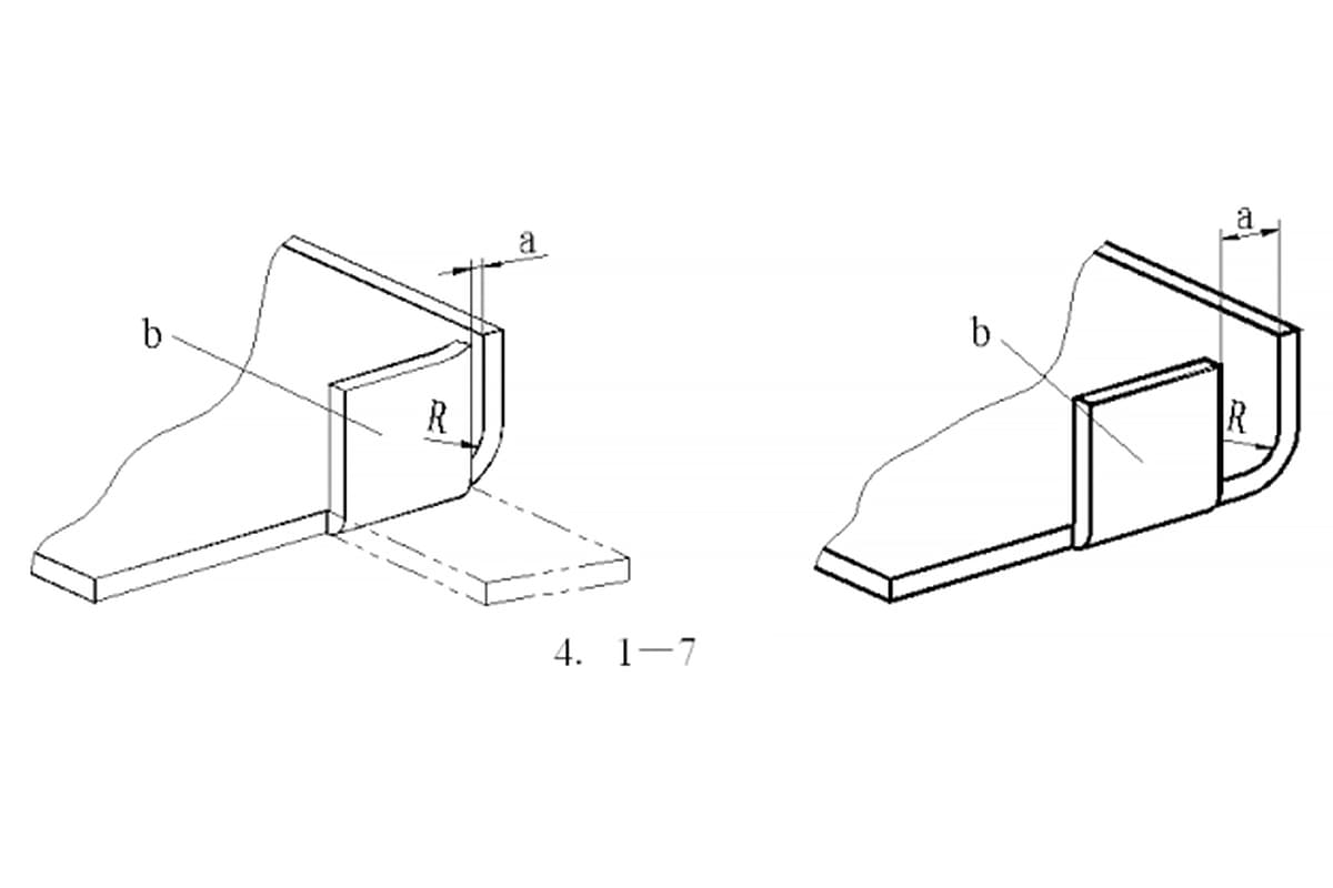
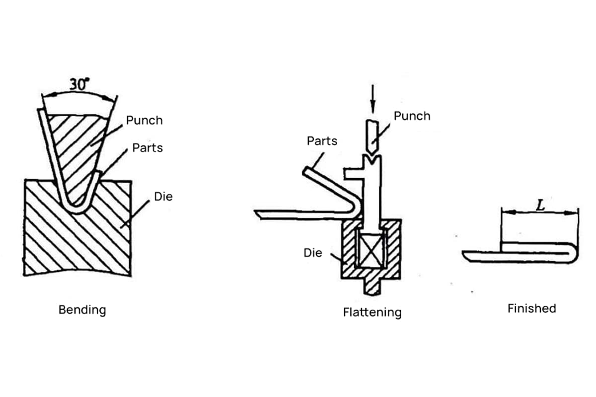
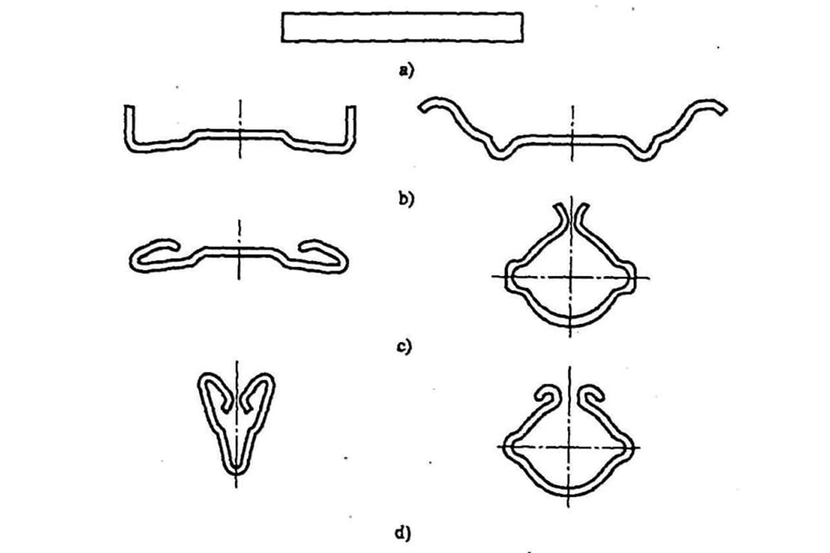
The forms of bending tools are displayed in Figure 7.
When processing, the appropriate tools are chosen based on the shape of the workpiece.
Most processing enterprises have a wide range of bending tools, especially those with a high level of specialization.
To bend various complex sheet metal parts, many custom-made bending tools of various shapes and specifications are used.
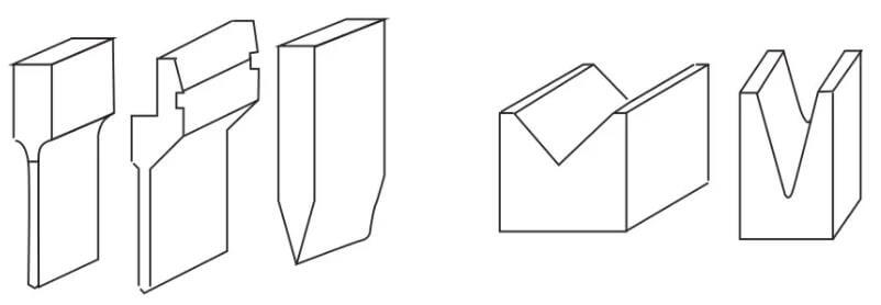
Fig. 7 Bending tool
Many factors can affect the bending process, including the arc radius of the upper die, material properties, material thickness, strength of the lower die, size of the lower die, and so on.
To meet product requirements and ensure the safety of the bending machine, sheet metal processing enterprises have standardized their bending dies.
It is important to have a general understanding of the available bending dies during the structural design process.
As seen in Figure 7, the left side represents the upper die and the right side represents the lower die.
The basic principle of bending is to use the bending knife (upper die) and V-groove (lower die) of the bending machine to shape the sheet metal parts.
Bending accuracy:
One fold: ± 0.1mm
Two fold: ± 0.2mm
Three fold: ± 0.3mm
and so on.
The use of the K-factor method in three-dimensional modeling software for sheet metal unfolding calculation results in highly precise unfolding drawings that can be directly exported. This eliminates the need for sheet metal unfolding technicians to redraw the unfolding drawings, improves the processing efficiency of sheet metal production enterprises, and reduces the delivery cycle.

As the founder of MachineMFG, I have dedicated over a decade of my career to the metalworking industry. My extensive experience has allowed me to become an expert in the fields of sheet metal fabrication, machining, mechanical engineering, and machine tools for metals. I am constantly thinking, reading, and writing about these subjects, constantly striving to stay at the forefront of my field. Let my knowledge and expertise be an asset to your business.