Top 10 Press Brake Manufacturers (2024 Updated)
In the vast world of manufacturing, one machine stands tall: the press brake. With its ability to bend and shape metal with precision and power, it has become an indispensable…
Have you ever wondered how to revolutionize your CNC press brake operations? This article explores two advanced hydraulic clamping designs that enhance efficiency and precision in sheet metal bending. By delving into the mechanics, benefits, and unique features of these clamping devices, you’ll discover how to achieve quicker die changes and improve bending accuracy. Learn how these innovations can elevate your manufacturing process and boost productivity in your workshop.
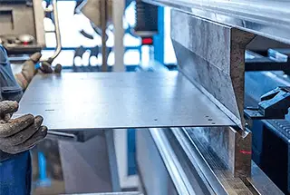
As one of the most widely used sheet metal bending equipment, the CNC press brake is widely used in the sheet metal processing and equipment manufacturing industry. It is a crucial supporting equipment for sheet metal processing along with CNC turret punch, CNC plate shearing machine, and CNC laser cutting machine.
The CNC press brake works by using a simple general die and repeatedly moving the ram to bend the sheet into a variety of complex cross-sectional shapes. With the advancement of new technologies such as CNC, servo, and die, the CNC press brake technology is primarily focused on energy-saving and high efficiency.
Additionally, with the continuous improvement of bending accuracy and efficiency, various functional components are becoming increasingly available. Some companies with strong research and development capabilities are focusing on the design of various functional components, striving to improve the degree of automation in machine tools.
Among all the functional parts, the upper die quick clamping device has the most significant impact on bending accuracy and efficiency, particularly in multi-variety and small-batch bending production where the improvement of die change efficiency is particularly noteworthy.
This article introduces two new upper die clamping devices that are easy to operate, energy-saving, and efficient. The technical principle, mechanism design, technical characteristics, and working process are described in detail.
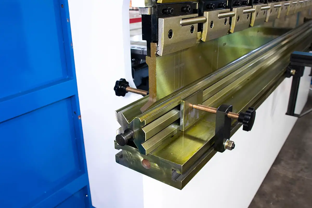
China’s CNC press brake upper die clamping device usually adopts mechanical structure, as shown in Fig. 1 and Fig. 2.

The eccentric quick clamping mechanism shown in Fig. 1 is characterized by having a cam rod at the end of the operating handle. The operating handle is securely attached to the front clamping block via a cylindrical pin and a spring is clamped between the front clamping block and the fixed block.
To quickly clamp the upper die of the press brake machine, the upper die must be inserted from the side of the quick clamping device. The die can be quickly clamped by rotating the operating handle.
When the operating handle is rotated in the reverse direction, the front clamping block is quickly reset by the spring between the front clamping block and the fixed block, releasing the die and allowing it to be transported out from the side.
The device is user-friendly and easy to operate, but it does have some limitations, such as an uneven clamping force and the need to insert the die from the side.
Figure 2 features a threaded quick clamping mechanism. To quickly clamp the die of the press brake machine, the upper die must be inserted from the side of the quick clamping device.
The operating handle is rotated to drive the screw, which in turn drives the front clamping block to move forward and clamp the die. When the handle is rotated in the reverse direction, the front clamping block moves backward, driven by the screw, to release the die and transport it from the side.
This structure offers the advantages of having a large clamping force, good self-locking capabilities, and simple operation. However, it does have some limitations such as uneven clamping force and a slower clamping speed.
In this paper, two solutions are proposed to address the stress situation and size of the upper die of the press brake machine, based on the characteristics of the hydraulic automatic clamping device for the upper die of the bending machine.
Scheme 1:
The die is secured by the force of expansion generated when pressure oil is injected into the compressed rubber hose.
Both ends of the clamping device are equipped with a safety lock.
When the upper die is secured, the safety pin on the safety lock is inserted into the pinhole on the die.
When the internal pressure of the rubber hose dissipates, the operator and die are effectively protected.
The hydraulic automatic clamping device is ideal for large-scale forming dies, such as those used in the automobile industry to press arc-shaped doors and windows.
Scheme 2:
The force generated by the compression hose is utilized to extrude the die as well.
Furthermore, the hydraulic automatic clamping device is equipped with a mechanism for compensating for the deflection of the upper die and a safety locking mechanism.
The upper wedge of the deflection compensation mechanism can be adjusted to extrude the top pin, thereby compensating for any deflection in the upper die.
The safety pin in the safety locking structure provides effective protection for both the operator and the upper die.
This hydraulic automatic clamping device is suitable for use with standard dies and can accommodate segmented dies.
According to the design idea of scheme 1, the hydraulic automatic clamping device of upper die as shown in Fig. 3 and Fig. 4 can be obtained.
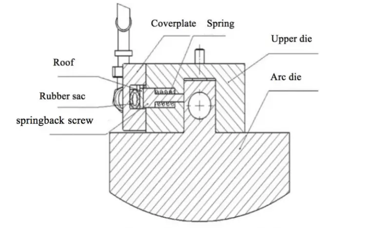
Fig. 3 Scheme 1: Upper die hydraulic automatic clamping mechanism
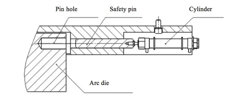
Fig. 4 Safety lock mechanism
The hydraulic automatic clamping device for the upper die comprises of a clamping mechanism and a safety locking mechanism. The components of the clamping mechanism include the upper die base, rebound screw, top plate, spring, cover plate, rubber bag, follow-up hose, transition joint, and plug.
The upper die base is securely attached to the bottom of the sliding block using screws. The upper die seat has a vertical groove to hold the upper die handle and several parallel countersunk holes on one side. The rebound screws for extrusion dies and springs for spring-back reset are placed in these countersunk holes.
The cover plate is fixed on the side of the upper die base and has a through groove. A top plate and a rubber tube are inserted through this groove, with the top plate positioned between the rebound screw and the rubber tube. The hose is in a compressed state when not in use.
As shown in Fig. 4, a safety lock mechanism is located on either side of the clamping device and consists of an air cylinder and safety pin. Pinholes are positioned on the left and right sides of the upper die seat and the press brake machine.
When the upper die is clamped, the cylinder pushes the safety pin through the pinhole in the upper die seat and into the pinhole in the upper die to ensure that the upper die remains suspended in the groove of the upper die seat even if the internal pressure of the rubber hose suddenly drops. This guarantees the safety of both the operator and the die.
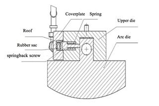
Following the design concept of scheme 2, a second hydraulic automatic clamping device for the upper die can be produced, as shown in Fig. 5, 6, and 7.

The schematic diagram of the hydraulic automatic clamping device of the upper die reveals that it comprises a clamping mechanism, a deflection compensation mechanism, and a safety locking mechanism.
The device consists of a first cover plate, a clamping head, a top plate, a rubber tube, and a clamping head.
The bottom of the sliding block is fixed to the upper die base with screws.
The upper die base has a horizontal through groove on the bottom and a first countersunk hole on the side.
The first countersunk hole is fitted with a first spring, which is placed on the surface of the springback screw.
The springback screw passes through the first countersunk hole and interacts with the upper die handle of the bending machine.
The through pipe has one end equipped with a through pipe, while one end of the rubber pipe is connected to the rubber sac.
A roof is positioned between the hose and the springback screw.
In its initial state, the hose is compressed by the preload of the first spring.
The device shown in Fig. 6 includes a safety locking mechanism consisting of a safety pin, a jacking screw, and a second spring. The mechanism is designed to ensure the safety of the operator and the die in case the clamping mechanism stops working.
The side of the upper die base is equipped with several second countersunk holes. One end of these holes is connected to the horizontal through groove, while the other end is threaded. The safety pin passes through the second countersunk hole and engages with the groove of the upper die on the bending machine. The preload of the second spring can be adjusted by rotating the top screw, which regulates the extrusion force between the safety pin and the upper die.
In addition to the safety locking mechanism, the device also includes an upper die deflection compensation mechanism, as shown in Fig. 7. This mechanism consists of several upper wedges, lower wedges, jacking pins, disc spring groups, and a third spring.
The upper part of the upper die base features multiple grooves, each equipped with two third countersunk holes. One end of the third countersunk holes is connected to the lower part of the upper die base. The upper and lower wedges are installed in the groove of the upper die base and connected to it by screws. A disc spring group is positioned between the upper wedge and the upper die base.
A third spring is placed on the surface of the ejector pin and installed in the third countersunk hole. The ejector pin engages with the upper die on the bending machine through this hole.
Scheme 1:
The first step in using a press brake machine is to place the upper die onto the lower die of the worktable, either through manual operation or with the help of a manipulator. The sliding block then drives the upper die seat to move downwards.
Next, the upper die handle is inserted into the groove of the upper die base and the sliding block moves to the bottom dead center. The relevant hydraulic system is then activated.
Pressure oil enters the rubber tube for stamping, causing the tube to expand and extrude the top plate and cover plate. Since the cover plate is fixed to the upper die base, the roof extrusion causes the spring back screw to extend, which in turn clamps the upper die handle and spring.
The cylinder in the safety locking mechanism then pushes the safety pin into the pinhole of the upper die seat and enters the pinhole of the press brake machine. During the bending process, if the middle pin is pressed, the safety die is pulled out from the air cylinder.
Once the bending is complete, the pre-tightening force of the spring ejects the springback screw, releasing the upper die of the machine. The die can then be changed manually or with the help of the manipulator.
Scheme 2:
When operating the device, first insert the upper die handle of the bending machine into the through groove of the upper die base either manually or with the help of a manipulator. Overcome the preload of the second spring by sliding the upper die handle along the chamfered edge of the safety pin in the safety device.
Once the upper die handle has been fully inserted into the through groove of the upper die base, press the safety pin into the groove of the upper die of the bending machine. The safety locking mechanism will then lock and secure the upper die of the bending machine in place.
The pre-tension force of the second spring can be adjusted by turning the top screw, thus adjusting the extrusion force between the safety pin and the upper die of the bending machine.
After all the required upper dies have been placed into the device, close both the upper and lower dies of the bending machine and activate the relevant hydraulic system.
Pressure oil will then flow into the inner part of the rubber tube, causing it to expand and extrude the top plate and cover plate. The cover plate and upper die seat are fixed in place by screws, so as the roof extrudes, it also pushes the rebound screw, which in turn compresses the first spring and clamps the upper die of the bending machine.
At this point, the bending machine’s upper die deflection compensation mechanism can be utilized. To do this, adjust the position of the upper wedge by turning the second screw clockwise.
The upper wedge will then extrude the disc spring group and the lower wedge, causing the lower wedge to extrude the ejector pin. The ejector pin then compresses the second spring and the upper die of the press brake machine, effectively compensating for any deflection of the upper die.
When the deflection compensation is cancelled, turn the second screw counterclockwise and move the upper wedge backwards by the preload of the disc spring group.
The jacking pin and the lower wedge are lifted by the preload of the second spring, causing the deflection compensation of the upper die to disappear.
When changing the die, first release the pressure of the rubber tube. The first spring will then eject the spring-back screw through the pre-tightening force, causing the rubber sac to flatten and releasing the upper die of the bending machine.
Remove and replace the upper die of the bending machine through manual operation or manipulator operation, overcoming the preload of the third spring.
The processing and manufacturing industry is rapidly developing and automation is rapidly improving, so the demand for efficient die change in press brake machines is growing. As a result, it is crucial to develop a rapid clamping device for the upper die of press brake machines.
Research in this technology not only advances the die changing technology and increases efficiency, but it also enhances bending accuracy. When used properly, this technology can improve the competitiveness of enterprises in the market and result in substantial economic benefits.

As the founder of MachineMFG, I have dedicated over a decade of my career to the metalworking industry. My extensive experience has allowed me to become an expert in the fields of sheet metal fabrication, machining, mechanical engineering, and machine tools for metals. I am constantly thinking, reading, and writing about these subjects, constantly striving to stay at the forefront of my field. Let my knowledge and expertise be an asset to your business.