Essential Structural Designs for Common Bending Dies
Have you ever wondered how intricate the designs of bending dies can get? This article dives into the structural designs of common bending dies, from V-shaped to Z-shaped, explaining their unique features and applications. You’ll discover how each design meets specific bending requirements and improves precision in metalworking. By reading, you’ll gain insights into the mechanics behind various bending die structures and learn which designs are optimal for different manufacturing scenarios.
The structure of a bending die varies depending on the characteristics of the bent part (shape, size, precision level, etc.) and production volume. The complexity varies, and there are numerous forms. Here, we only briefly introduce some common bending die structures.
1. V-shaped Bending Die
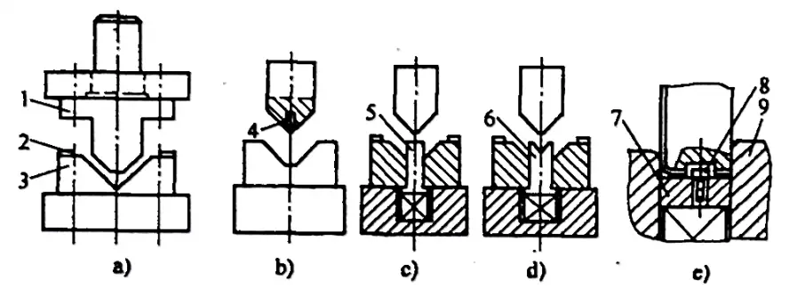
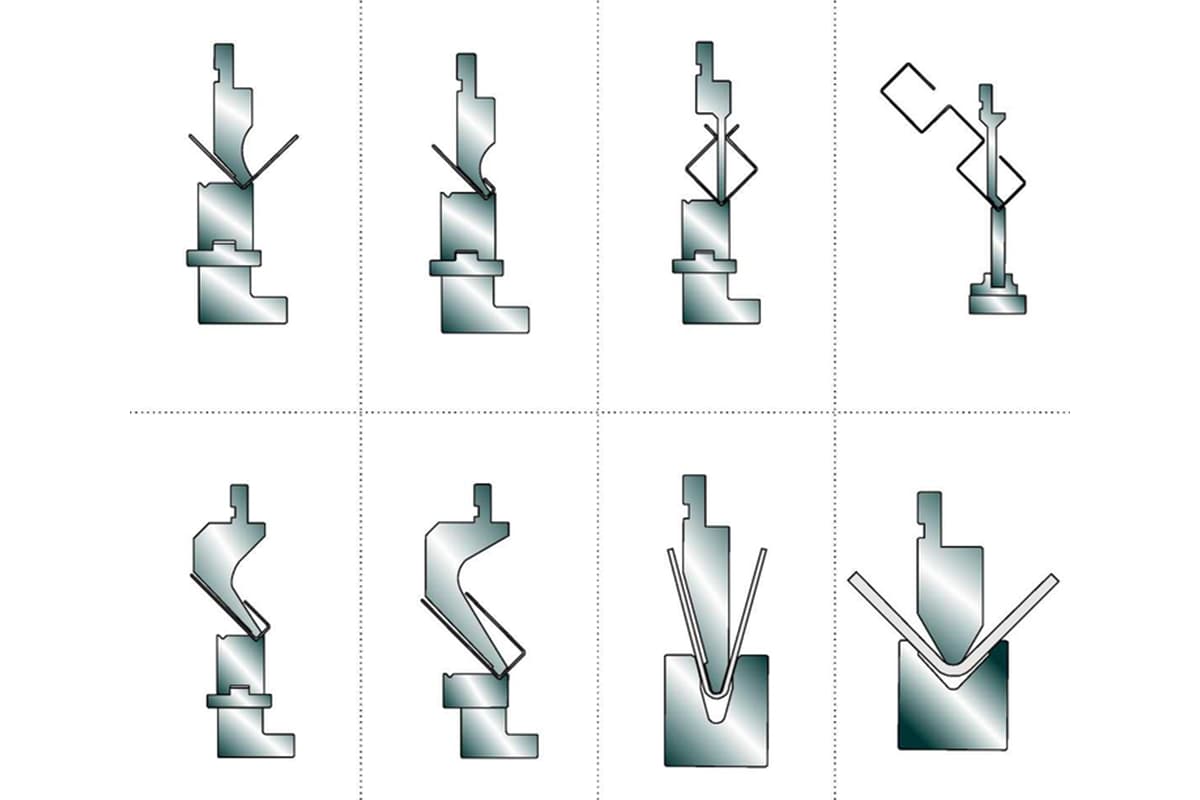
There are many forms of the commonly used V-shaped bending die structures, as shown in Figure 2-23.
Figure 2-23: Schematic Diagram of Common V-Shaped Bending Die Structure
1 – Punch
2 – Positioning Plate
3 – Die
4 – Positioning Pin
5 – Ejector Rod
6 – V-Shaped Ejector Plate
7 – Ejector Plate
8 – Positioning Pin
9 – Backstop.
1) The structure shown in Figure 2-23a is a common V (or L) shaped part bending die structure. Its characteristics are simplicity and versatility, but with lower efficiency and precision.
2) The structures shown in Figures 2-23b to 2-23d are bending die structures with positioning pins, ejector rods, and V-shaped ejector plates. Their feature is that they can prevent the workpiece from shifting during bending, improving the precision of the bent parts.
3) The structure shown in Figure 2-23e is a bending die structure with positioning pins and an ejector plate. It can effectively prevent the workpiece from shifting during bending, improving the precision of the bent parts, and capable of processing bent parts with a side length tolerance of 0.1.
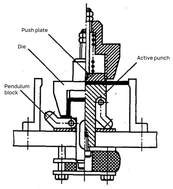
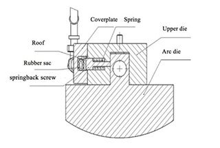
4) Figure 2-24 shows a V-shaped bending die structure with a flip plate. Its working principle is: The two parts of the die are connected together by a dumpling chain and inserted into the pivot in the two pillars, keeping the center vertical, and bending the part along with the die. When the punch retracts, the die flips and is returned to its starting position with the help of the buffer ejector rod below.
Its feature is: During the bending process, the sheet metal workpiece is always in contact with the flip die, suitable for bending operations that do not have sufficient support area for pressing and are narrow and long.
Figure 2-24: V-Shaped Bending Die Structure with Flip Plate
1 – Punch
2 – Pillar
3 – Positioning Plate
4 – Flip Die
5 – Dumpling Chain
6 – Backstop
7 – Ejector Rod.
2. U-Shaped Bending Die
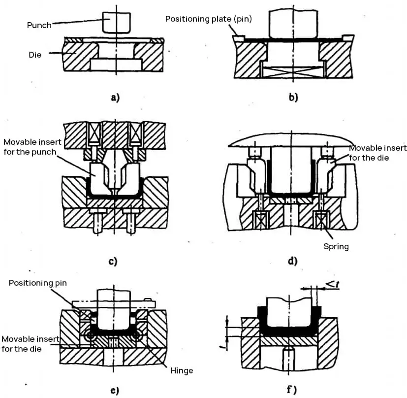
As per the diverse requirements of U-shaped components, commonly adopted bending die structures are illustrated in Figures 2-25 and 2-26. A brief introduction to their applications and characteristics is provided below.
Figure 2-25: Bending Die for U-Shaped Components
Figure 2-26: Bending Die for U-Shaped Components with a Bend Angle of Φ less than 90°
4) The structure shown in Figure 2-25d is used for components with higher internal dimensional requirements. When the blank thickness tolerance is large, the sides of the punch are made into movable inserts. Under the action of the spring, the punch width can be automatically adjusted according to the material thickness.
5) The structure shown in Figure 2-25 is used for components requiring coaxial holes on both sides. The movable inserts on both sides of the die have locating pins for blank positioning. When the punch descends, it presses the blank and the movable inserts into the die together, ensuring the coaxiality of the holes on both sides.
When the punch ascends, the movable die and the pressure plate return to the top of the die under the action of the spring. The downside is its complex structure and difficulty in manufacturing.
6) The structure shown in Figure 2-25f is for workpieces with thinning side walls.
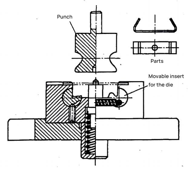
7) The structure shown in Figure 2-26 is used for bending U-shaped components with angles φ<90°. The movable inserts on both sides of the die can rotate within the cavity. During the press bending, the punch first bends the blank into a U shape.
When the punch continues to descend, the movable inserts on both sides of the die rotate and bend the blank into the U-shaped component to the desired angle φ<90°. When the punch ascends, the movable insert resets under the action of the spring, and the punch carries the part out of the die, and the part is unloaded from the punch along the Z-axis direction.
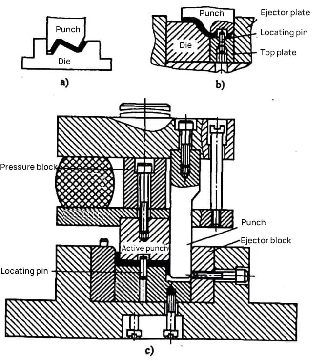
When the step height H is within 2t<H≤Z (the minimum bending edge height of the Z-shaped bend), consider using a step die or a simple die and a loading and unloading structure to press-bend into shape in one go, as shown in Figure 2-27.
1) The structure shown in Figure 2-27a is simple. However, without a pressing device, the blank can easily slip during press bending. It is only suitable for parts with low precision requirements.
2) Figure 2-27b shows a Z-shaped (step) bending mold structure with a top plate and locating pin, which effectively prevents the blank from sliding and shifting during the press bending process, thus improving the machining precision of the parts.
3) Before the press bending starts in the structure shown in Figure 2-27c, the movable punch and the punch are flush at the top under the force of a rubber sheet. As press bending starts, the movable punch and the top plate clamp the blank, and under the action of the rubber sheet force (>top plate spring force), the movable punch and the top plate descend, causing the left side of the blank to bend.
When the top plate contacts the lower mold base, the force of the top plate increases, compressing the rubber sheet. The punch descends, bending the right side of the blank into shape. When the upper mold base contacts the pressure block, the part is checked and corrected. This structure can achieve high-precision parts, but it is complex and difficult to manufacture.
Figure 2-27 Z-shaped (step) bending mold
4. Four-corner Bending Mold
Four-corner bending parts can be formed in one or two steps.
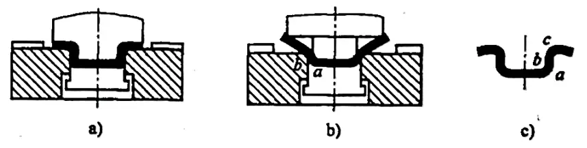
1) The structure of the simple one-step four-corner bending mold is shown in Figure 2-28. When bending parts with this mold structure, there often arises inaccuracies in the external corner shape and thinning of the straight-wall sections (especially when the material thickness t>1~1.5mm, and its straight-wall part is relatively tall).
This can be seen from the molding process shown in Figure 2-28b. When the male mold descends, the internal corner a bends at a fixed bending line position. However, the bending line position of the external corner isn’t fixed, first at point b, and finally at point c.
Therefore, the final part obtained is shaped as shown in Figure 2-28c, and the straight-wall section tends to thin out due to the tensile force during bending. As this bending mold structure is simple and easy to manufacture, it can be used when the part requirements are not high and production volume is not large.
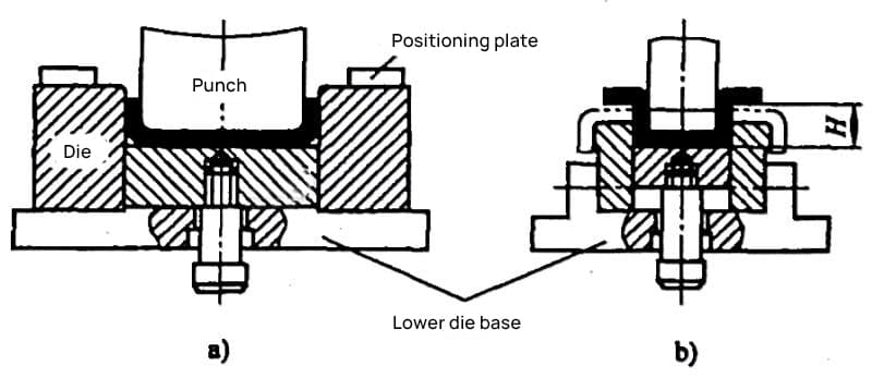
2) Figure 2-29 shows the structure of a two-step four-corner bending mold. This structure ensures that the internal and external corners bend on the bending line, thereby avoiding the thinning phenomenon shown in Figure 2-28c, and improving the quality of the bent parts. However, this mold has a low production efficiency and can only ensure sufficient strength of the concave mold when the height H of the bent parts (see Figure 2-29b) is >(12~15)t.
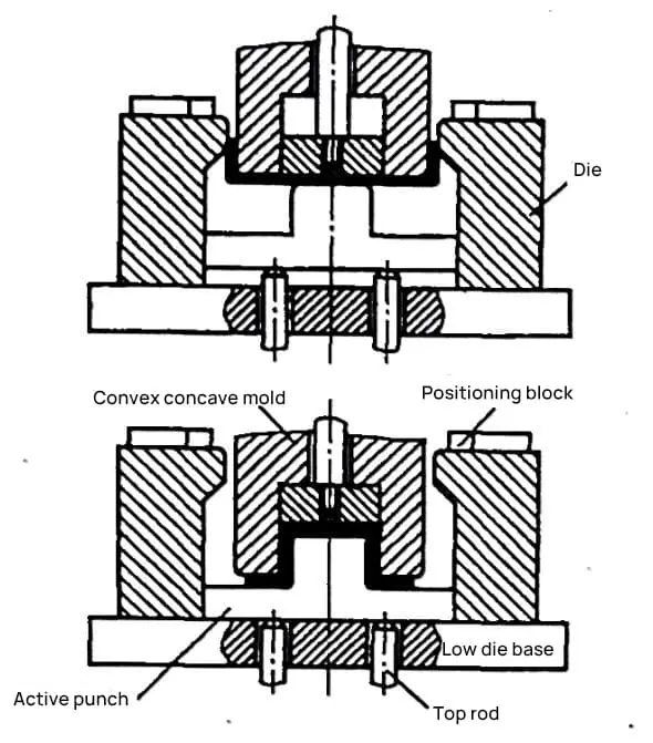
3) Figure 2-30 shows the structure of a two-step composite bending mold. This structure ensures that the internal and external corners bend on the bending line, thereby avoiding the bending deformation phenomenon shown in Figure 2-28. As the convex and concave molds descend, the blank is first bent into a U shape by the concave mold (convex-concave mold pushing force > active convex mold ejection force).
When the active convex mold contacts the lower mold base (active convex mold ejection force > convex-concave mold pushing force), the convex-concave mold continues to descend, and the active convex mold finally shapes the part by bending it. The disadvantage of this bending mold is that it requires a large cavity space in the lower mold to facilitate side forming of the part.
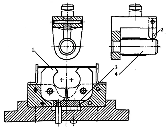
4) Figure 2-31 shows another structure of a two-step (with swinging block) composite bending mold. As the concave mold descends, the blank is first bent into a U shape by the active convex mold’s ejection force. The concave mold continues to descend and when it contacts the top of the top plate, it forces the convex mold to descend and the swinging block to rotate towards the side.
Under the force of the swinging block, the part is finally shaped by bending. The disadvantage of this composite bending mold is the complexity of the mold structure.
The bending method for cylindrical parts is typically determined by the diameter of the cylinder. For cylinders with a diameter (d) less than 5mm, it is considered small circular bending. For cylinders with a diameter (d) equal to or greater than 20mm, it is categorized as large circle bending.
(1) Bending of Small Circular Parts with Diameter (d) Less Than 5mm
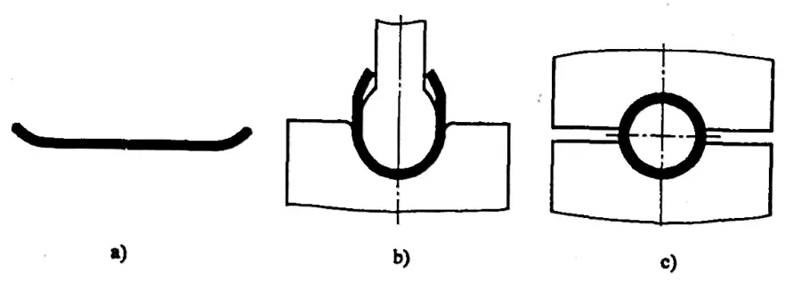
The bending process for small cylindrical parts involves first bending into a U-shape, then bending that U-shape into a cylindrical formation. This is done using two pairs of simple bending molds to form a cylinder, as shown in Figure 2-32.
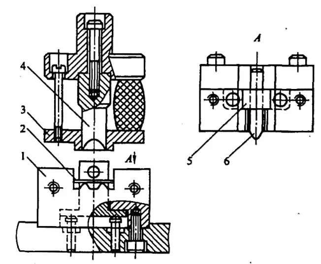
Due to the small size of the workpiece, it is inconvenient to perform the bending operation twice, so the two steps can be combined or a skip-step bending mold can be used for shaping. Figure 2-33 shows a one-step bending mold for small cylindrical parts.
When the upper mold descends, the pressure plate presses the slider down. The sinking determines that the core rod billet is first bent into a U-shape. As the upper mold continues to descend, the convex mold bends the U-shape into a cylindrical shape. This structure is suitable for soft materials and bending of small and medium diameter cylindrical parts.
Figure 2-32 Bending mold for small cylindrical parts formed in two steps
a) First step: Bending into a U-shape
b) Second step: Bending into a cylindrical shape
Figure 2-33 One-step bending mold for small cylindrical parts
1 – Concave mold
2 – Sheet material
3 – Pressure plate
4 – Convex mold
5 – Slider
6 – Core rod
(2) Bending of Large Circular Parts with Diameter (d) Equal to or Greater Than 20mm
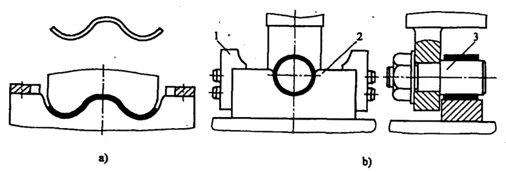
Figure 2-34 shows a one-step bending mold for large cylindrical parts with a swinging concave mold. As the convex mold descends, it initially forms the blank into a U-shape. As the convex mold continues to descend, the swinging concave mold bends the U-shape into a circular form.
The part can be removed by pushing the support along the direction of the convex mold axis. This mold has a relatively high production rate, but due to the rebound, there are gaps and a small amount of straight edge left at the part seam, resulting in poor part accuracy and a more complex mold structure. Figure 2-35 shows a two-step bending method for large cylindrical parts.
First, it is pre-bent into three 120° waves, then it is bent into a circular shape using the second pair of molds. The part is removed in the direction of the convex mold axis. Figure 2-36 shows a three-step bending method for large cylindrical parts, which has a lower production rate and is suitable for parts with larger material thickness.
Figure 2-34 One-step bending mold for large cylindrical parts
1 – Swinging concave mold
2 – Convex mold support
3 – Top plate
4 – Convex mold
Figure 2-35: Two-stage bending process for large circular simple parts.
a) The initial bend forms a 120° wave shape.
b) The second bend features: 1 – a positioning plate, 2 – a male die, 3 – a female die.
Figure 2-36: Three-step bending formation of large circular simple parts
a) First bending
b) Second bending
c) Third bending
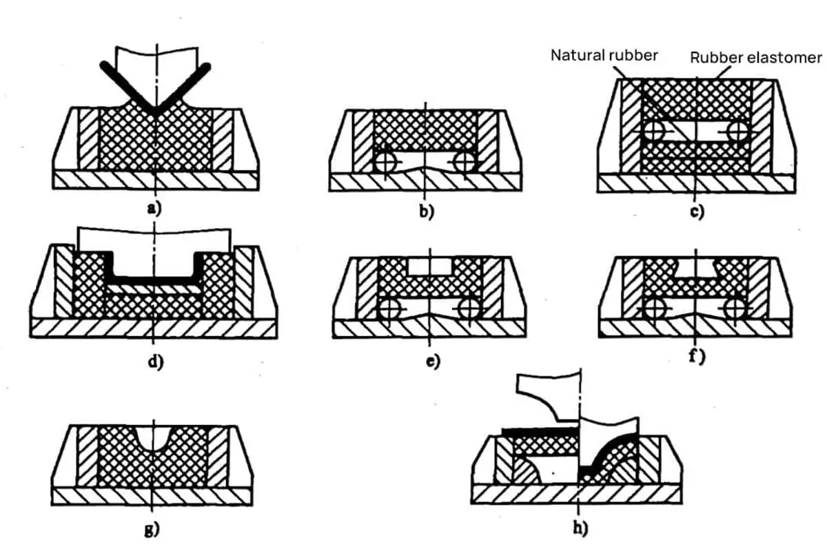
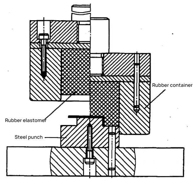
6. Rubber Bending Mold
Rubber bending mold substitutes the concave of the bending mold with rubber, while the convex part still uses a steel mold, as shown in Figure 2-37. The rubber can transmit pressure in all directions like a liquid within a sealed container. Compared with rigid bending molds, the bending process undergoes advantageous changes. Rubber or high-hardness (60-80AS) elastomers yield better results.
The processed bent parts not only have high precision and no surface scratches, but the universal nature of the rubber or elastomeric concave mold is also excellent. It is most suitable for processing single and small batch parts with high bending size precision and surface quality requirements, as well as parts made of softer materials.
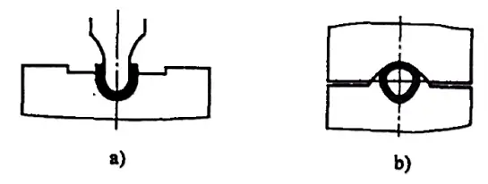
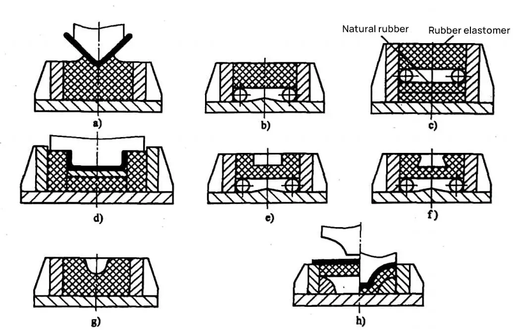
Figure 2-38 shows several common rubber bending mold concave container structures and bending methods.
Figure 2-38a is suitable for bending V-shaped parts with small radii.
Figure 2-38b is suitable for bending U-shaped parts and V-shaped parts with smaller radii.
Figure 2-38c is suitable for bending V-shaped parts with larger radii, spread open forming.
Figure 2-38d is suitable for bending U-shaped parts.
Figures 2-38e, f, g, h are respectively suitable for bending ring-shaped parts or special-shaped parts with wings on both sides, enclosed forming.
As the founder of MachineMFG, I have dedicated over a decade of my career to the metalworking industry. My extensive experience has allowed me to become an expert in the fields of sheet metal fabrication, machining, mechanical engineering, and machine tools for metals. I am constantly thinking, reading, and writing about these subjects, constantly striving to stay at the forefront of my field. Let my knowledge and expertise be an asset to your business.
Have you ever wondered how to revolutionize your CNC press brake operations? This article explores two advanced hydraulic clamping designs that enhance efficiency and precision in sheet metal bending. By…
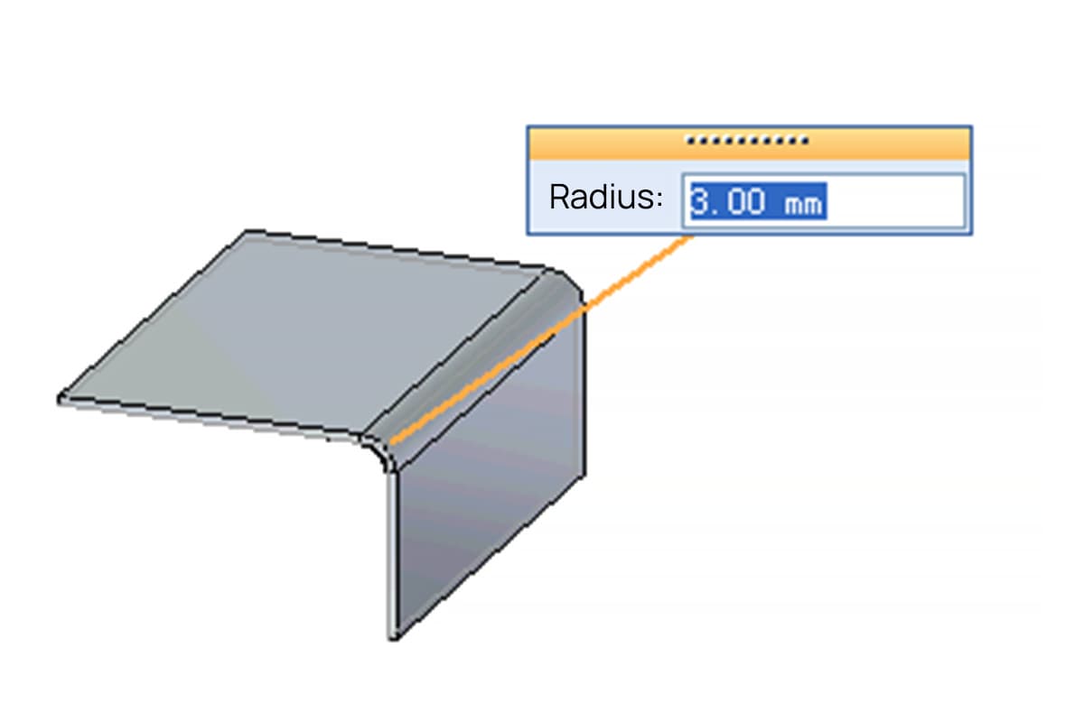
Have you ever pondered the importance of bend radius in mechanical design? In this article, we'll explore this crucial concept and its impact on material integrity. Drawing from the expertise…
Imagine shaping metal with such precision that it transforms into complex, custom forms effortlessly. That's the magic of press brake tooling, a vital process in sheet metal fabrication. In this…
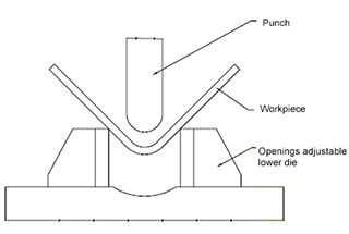
How does the size of the lower die opening affect the final dimensions of metal parts in air bending? This question is crucial for ensuring precision in metal fabrication. The…