0° – 180° Bend Allowance Chart for Sheet Metal Bending
Have you ever wondered how sheet metal parts are designed and manufactured with precision? In this blog post, we'll dive into the fascinating world of bend allowance - a crucial…
What ensures the perfect bend in sheet metal? This article unpacks five crucial factors that can make or break your sheet metal bending projects, covering essential aspects like minimum bending radius, bending height, hole margins, bending line position, and the importance of positioning holes. Readers will gain a deeper understanding of these fundamental principles, ensuring precision and quality in their metalworking tasks.
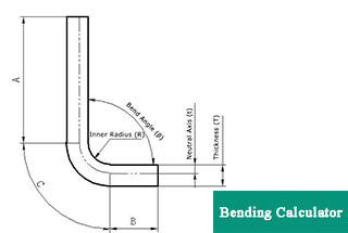
The minimum bending radius refers to the radius of the inner bend corner, provided that the outer fibers of the sheet do not break during the bending process.
It is only necessary to specify the minimum bending radius upon special request, and it should be increased as much as possible under normal conditions.
Table 1 lists the minimum bending radii for various thickness series of commonly used sheet metal materials.
Table 1 Minimum bending radius
| Thickness (mm) | 1 | 2 | 3 | 4 | 5 | 6 | 8 | 10 | 12 |
|---|---|---|---|---|---|---|---|---|---|
| Materials | |||||||||
| Q195 | 2 | 2 | × | × | × | × | × | × | × |
| Q235 | × | × | 5 | 5 | 5 | 10 | 10 | 10 | 15 |
| Q345 | × | × | 5 | 5 | 10 | 10 | 10 | 15 | 15 |
| Commonly used aluminum alloy sheet | 2 | 2 | 2 | 5 | 5 | 5 | × | × | × |
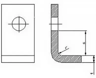
2.1 To ensure the quality of the bent workpiece, the straight edge of the bent parts should not be less than the minimum bending height.
When bending to form a right angle, as shown in Figure 1, the minimum bending height is determined by formula (1).
hmin = r+2t·····················(1)

Fig. 1
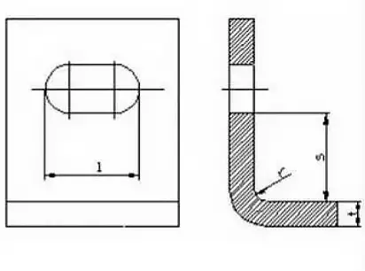
2.2 Special requirements of the bending height:
If the design needs to bend the bending height h ≤ r + 2t, the first thing needs to do is to increase the height of the bending, then bend and process it to the required size.
After processing shallow arc grooves in the bending deformation zone, bend again, as shown in Figure 2.
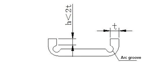
Fig. 2
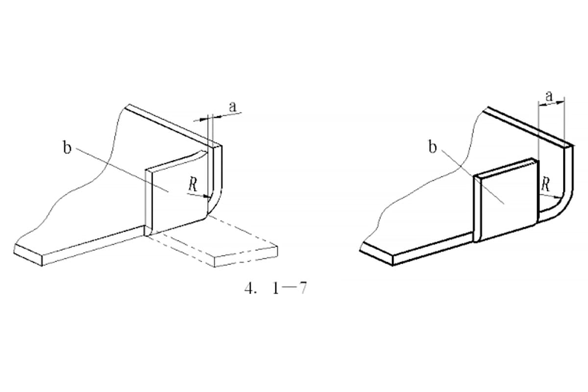
2.3 Height of the straight edge of the bent side with beveled corners.
When bending a bent piece with beveled side edges, as shown in Figure 3.
The minimum height of the side edges is as in equation (2).
hmin = (2~4) t > 3mm···············(2)
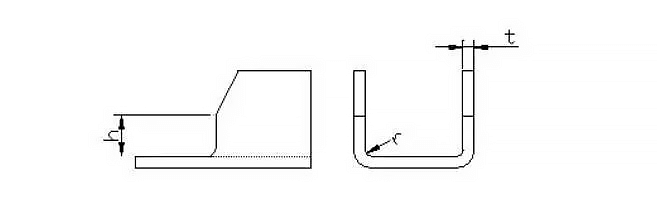
Fig. 3
When a bend is required after punching, the hole should be positioned outside the bending deformation area to prevent it from becoming deformed during the bending process.
The distance of the hole edge from the inner surface of the bent edge is shown in Table 2.
Table 2: Minimum hole margins
 |  | ||
|---|---|---|---|
| t (mm) | s (mm) | ||
| t (mm) | s (mm) | ≤25 | s≥2t+2 |
| ≤2 | s≥t+r | >25-50 | s≥2.5t+2 |
| >2 | s≥1.5t+r | >50 | s≥3t+r |
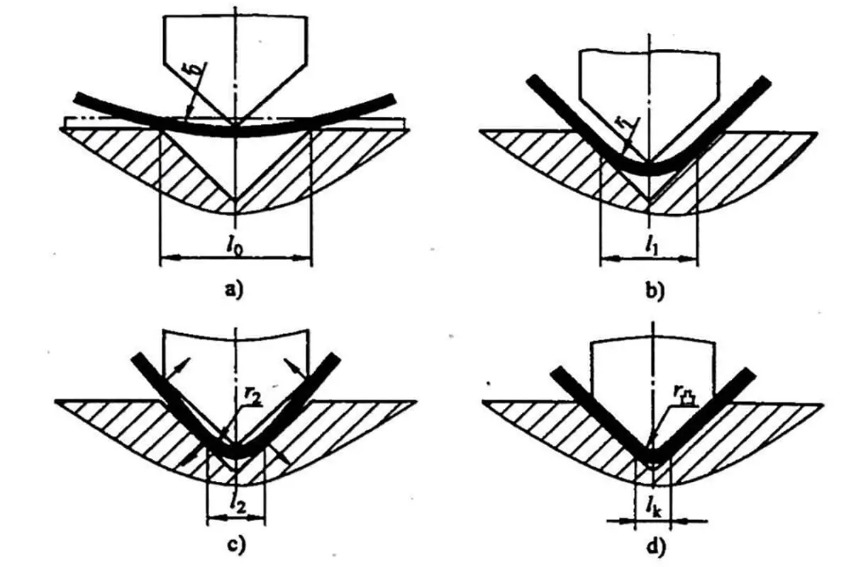
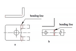
4.1 When partially bending a section, the bend line should not be at a location of dimensional abruptness to avoid bending cracks caused by stress concentrations at the sharp corners of the dimensional change.
The distance S from the mutation should be greater than the bending radius r, see Figure 4a.
Or punching process holes or grooves to separate the deformation zone from the non-deformation, see Figure 4b, 4c.
Note the size requirements of the figure: S ≥ R; slot width k ≥ t; slot depth L ≥ t + R + k / 2.

Figure 4
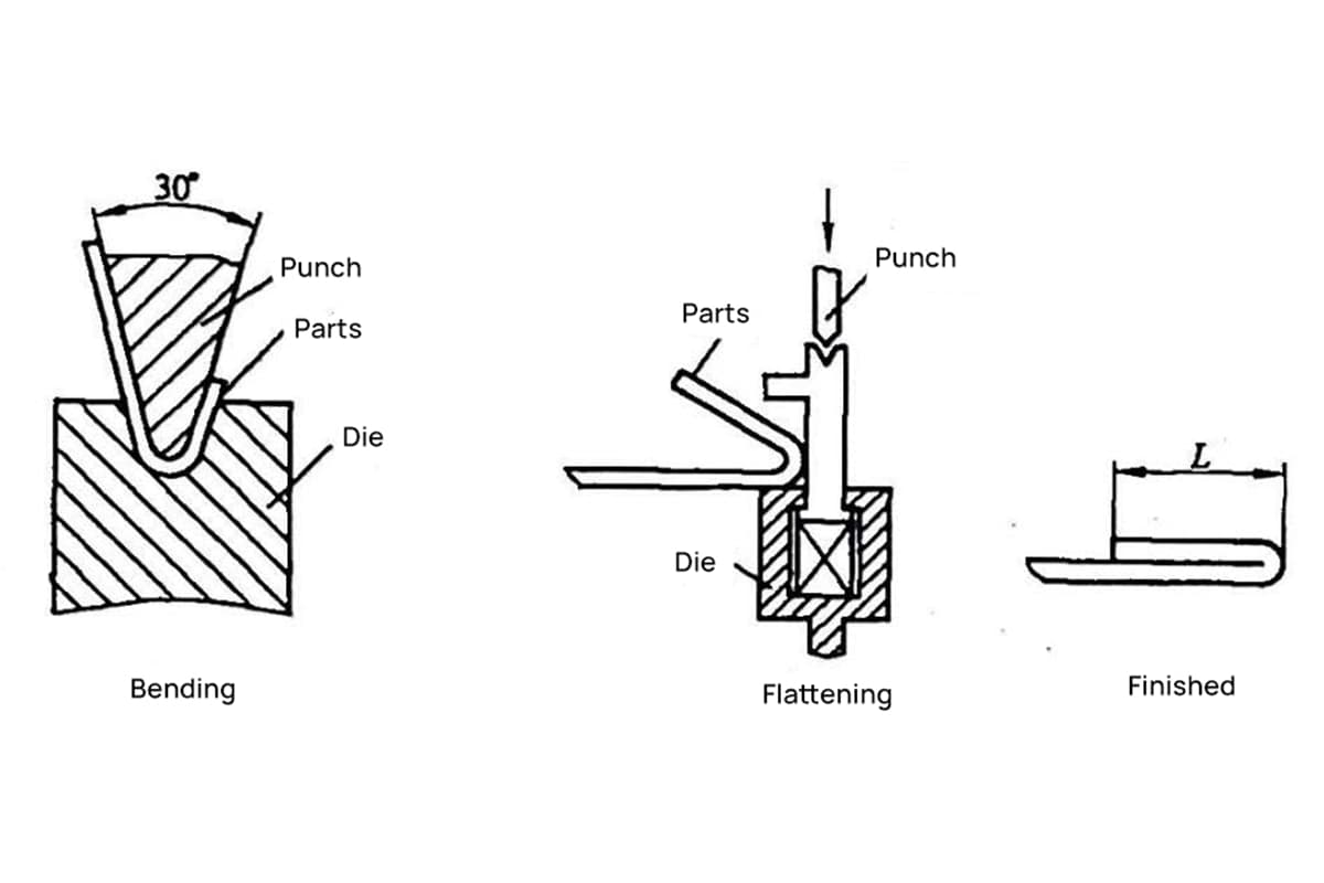
4.2 When the hole is located in the bending deformation zone, the process measures to be taken before bending is shown in Figure 5.

Fig. 5
To ensure the precise positioning of the sheet in the die and prevent movement during bending that leads to wasted product, the bent parts should be designed with process positioning holes, as illustrated in Figure 6.
Particularly for parts formed through multiple bends, process holes must be used as reference points for positioning to reduce cumulative error and guarantee product quality.
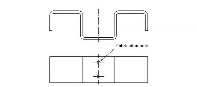
Fig. 6

As the founder of MachineMFG, I have dedicated over a decade of my career to the metalworking industry. My extensive experience has allowed me to become an expert in the fields of sheet metal fabrication, machining, mechanical engineering, and machine tools for metals. I am constantly thinking, reading, and writing about these subjects, constantly striving to stay at the forefront of my field. Let my knowledge and expertise be an asset to your business.