Press Brake Operation Manual (Training PDF)
Attention all mechanics and engineering enthusiasts! Have you ever wondered about the ins and outs of operating a press brake machine? In this blog post, we'll dive into the world…
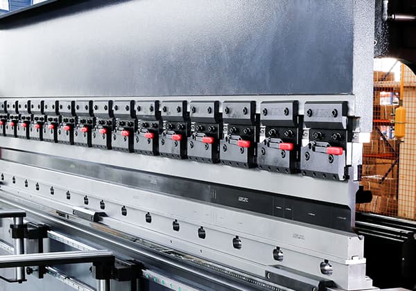
Ever tried changing press brake dies and wondered about the safest way to do it? This article guides you through the critical steps of safely removing and installing press brake dies, ensuring both efficiency and operator safety. From locking out the main power to aligning and fastening the dies correctly, it covers essential techniques and safety precautions. Learn how to avoid common hazards and ensure your press brake operates smoothly and securely.
DANGER
CRUSH AND SEVER HAZARD
ALWAYS follow your company’s machine specific lockout/tagout procedure before changing dies on this press brake.
These steps must be followed BEFORE removing or installing dies or die holders:
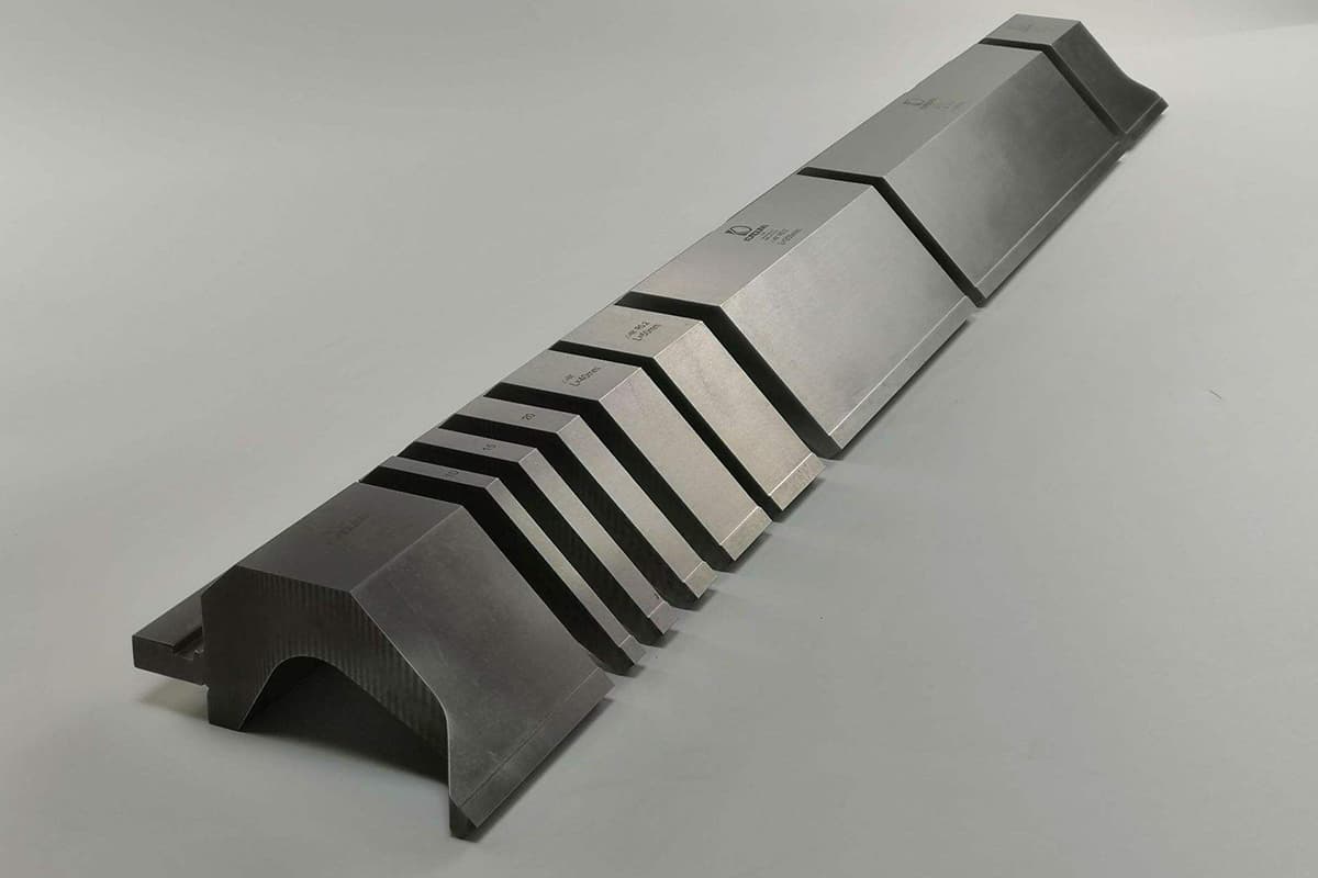
Dies and die holders can be heavy and awkward to lift by hand.
ALWAYS lift lightweight dies (<10 kg or <22 lbs) using proper lifting and carrying techniques. It is recommended that all dies be transported on a die truck or cart to avoid injury to operators and to protect the dies from accidental damage.
Proper lifting equipment and practices must be appropriate for the weight involved. Any dies over 22.7 kg (50 pounds) should be handled by a hoist.
When lifting dies, fiber slings should be used to prevent damage to die surfaces. Ensure the die or die holder is well balanced within the fiber slings.
CAUTION
Falling Die Hazard:
Dies and die holders must be aligned when the control is in HAND mode. This ensures the operator’s hands are away from the point of operation.
1. Press Ram Positioning
Before turning the main power OFF, check that the distance between the press ram and bed is approximately 1/8″more than the sum of the punch and lower die assembly (die and optional lower die holder) when the punch is bottomed out in the die.
2. Punch Removal
DO NOT simply unfasten the die clamping screws for removal.
This will help ensure that the punch does not fall forward onto the operator/helper.
To remove the punch:
1. Release the STOP button by rotating it 1/4 turn clockwise.
2. Push the green START pushbutton to start the main motor.
3. Set the control mode to HAND.
4. Set the operating mode to JOG. Lower the press brake ram until the tip of the punch is approximately 1/8
from the bottom of the”V”in the die.
5. Push the red STOP pushbutton to stop the main motor.
6. Lock out the main disconnect switch and secure the ram from movement.
7. Loosen the die clamping screws and slide the punch out at one end of the press brake.
NOTE:
If your press brake is equipped with the optional hydraulic Quick Clamp system, turn the keyswitch on the control box to ACTIVATE and hold it in this position.(The keyswitch is spring loaded to normally stay in the LOCK position.)
Press the UNCLAMP button on the control and slide the punch out at one end of the press brake.
3. Die Installation
After the main power has been turned OFF and locked out, lift the lower die holder and die, sliding them onto the bed from one end of the press brake. Center the lower die assembly on the press brake bed but do not fasten down.
4. Punch Installation
NOTICE
Punch tooling should be equipped with a safety tang. Punch tooling without a safety tang is held by the clamping force of the die clamp bar.
Mechanical Clamping System:
To install a punch using the standard machanical clamping system:
1. Lift the punch and position it to slide into the groove of the press ram and the”V”of the die.
2. Once in place,tighten the die clamp bar socket head cap screws until the punch is secure.
3. Turn the main disconnect switch ON. Rotate the STOP button 1/4 turn clockwise to release. Press the start button. Turn the main power ON
4. Set the operating mode to JOG, then press and hold the SLOW key for 3 seconds, to ensure the press ram’s travel is in slow bending speed.
5. If a tonnage control option is included,it should be turned ON and adjusted to a minimum setting before attempting to seat the punch.
CAUTION:
Minimum tonnage is required to seat the punch. Excessive tonnage when seating the punch could damage the die, the ram, or the ram clamp bar. Care must be taken when installing dies with small and acute openings.
6. Lower the press ram until the 1/8″gap between the punch and die has been closed.
7. Torque to the die clamp fasteners to secure the punch in position.
8. To seat the punch in the ram groove, lower the press ram to adequate seating tonnage for the specific die set.
The tonnage reading on the ETS control must not exceed the maximum rated load/foot or load/meter for the die set.
9. While maintaining the punch seating force, clamp the punch to the ram by torquing the die clamp bar socket head cap screws to a clamping torque that will ensure the punch is held securely to the ram. Due to the varying sizes and weights of punches, the required torque will vary. The maximum die clamp bolt torque must not exceed the seating torque for the given bolt size.
Hydraulic Clamping System (Optional):
To install the punch using the optional hydraulic Quick Clamp control:
1. Turn the keyswitch on the control box to ACTIVATE and hold it in this position.
2. Press the UNCLAMP control button.
3. Lift the punch, position and slide it into the groove of the press ram and the”V”of the die.
4. Set the operation mode to JOG.
5. Preset the ram pressure so that the tonnage does not exceed the maximum rated die pressure.
6. Turn the main power ON and lower the press ram until the 1/8″gap between the punch and die has been closed.
7. To seat the punch in the ram groove, lower the press ram until the preset pressure has been reached, as indicated on the pressure gauge.
8. While maintaining the preset seating force, clamp the punch to the ram by pushing the CLAMP button on Quick Clamp control box.
5. Tooling Centering
Centering the punch and die can be completed while the punch is being seated in the press ram.
Precise centering of the punch and die can be achieved using feeler gauges to check the punch-die shoulder gap while the punch is positioned near the die bottom.
Use the provided fasteners (set screws,T-bolts,and/or adjuster blocks)to center the die.
6. Die Fastening
The lower die assembly should be securely fastened to the press bed.
The die has a tang which fits into the groove on top of the lower die holder. Set screws are provided on the front and rear faces of the press bed for centering adjustments and fastening.
The lower die holder can be ordered either with or without a tang for fastening to the press bed. In either situation, provisions for fastening are included.
Adjustment and fastening of the lower die assembly are not considered complete until some sample bends have been created.
All dies must be securely fastened to the press brake, using the appropriate type of fasteners, to prevent injury to personnel or damage to the press brake and its tooling.
DO NOT simply unfasten the die clamping screws for removal. Prior to die removal, the ram should be lowered so that the tip of the punch is inside the “V” opening of the die. This will help ensure that the punch does not fall forward onto the
operator/helper.

DANGER
SERIOUS BODILY INJURY HAZARDS:
The operator will need to perform a number of trial bends and adjustments to achieve the required shape or angle.
The press ram position controls, press ram/bed parallel adjustment, and die shimming will affect the included angle of the formed part.
Performing a Test Bend
1. Set the operating mode to JOG.
2. Take two similar small flat test pieces and place one across each end of the die.
3. Using the palm pushbuttons or the footswitch, jog the press ram down to an adequate clearance position. Press the HIGH key for three seconds. This will set the high position for the cycle.
4. Jog the press ram down to where the punch is almost in contact with the part to be formed.At this point set the SLOW speed change position by pressing the SLOW key for three seconds.
5. Jog the press ram down so the punch forms the test pieces to approximately the desired angle.
6. Press and hold the BEND key for three seconds.This will set the press ram bend position for this angle.
7. Check the test bend pieces for equal angle forming at both ends of the press ram.
8. Press Ram/Bed Parallel Check
– Take two similar small flat test pieces and position one across each end of the die.
– Set the operation mode to MANUAL and bring the press ram down until the DOWN LIMIT light comes on.(The press ram should have changed into the slow speed mode just prior to contacting the test piece.)
– Release the palm pushbuttons or footswitch to return the ram to its up-limit.
– Measure the two formed test pieces. If the angles are not equal, the punch and die are not parallel.
– Reset the press ram parallel adjuster assembly and continue making test bends until both pieces have the same angle.
9. Set Bend Point(Fine)
– When identical pieces have been made, measure to ensure that they are at the desired angle. If the angle is too great, the press ram has not traveled down far enough. If too small, the press ram has traveled down too far.
10. Die Shimming
– Full-length consistency of formed parts may require shimming between the lower die holder and the press brake bed cap. This should compensate for deflections of the press ram and bed due to applied loads.

As the founder of MachineMFG, I have dedicated over a decade of my career to the metalworking industry. My extensive experience has allowed me to become an expert in the fields of sheet metal fabrication, machining, mechanical engineering, and machine tools for metals. I am constantly thinking, reading, and writing about these subjects, constantly striving to stay at the forefront of my field. Let my knowledge and expertise be an asset to your business.