Balance Valve: Understanding the Structure and Principle
Have you ever wondered how complex hydraulic systems maintain stability under varying loads? The balance valve plays a crucial role. This article explains the structure and working principle of balance valves, essential for load control and safety in hydraulic systems. By the end, you’ll understand how these valves prevent unwanted movements, ensure safety, and improve efficiency.
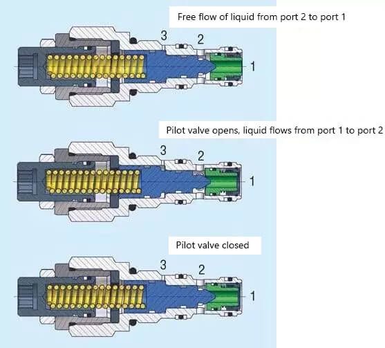
The hydraulic balancing valve enables the unrestricted flow of oil from port 2 to port 1, as evidenced by the schematic diagram at the top of the figure below.
When the oil pressure at port 2 is higher than the pressure at port 1, the green part of the spool moves towards port 1 due to the force of the oil pressure, causing the check valve to open and allowing oil to flow freely from port 2 to port 1.
However, the flow of liquid from port 1 to port 2 is blocked until the pressure at the pilot port reaches a certain level, causing the blue spool to move to the left and opening the valve port. This allows oil to flow from port 1 to port 2.
If the pilot pressure is not strong enough to open the blue spool, the valve port closes and the flow of fluid from valve port 1 to valve port 2 is shut off.
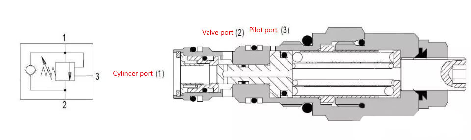
The symbol for the balancing valve is shown below:
The role of the balance valve
Load Holding:
The balancing valve helps to prevent the unintended downward movement of the hydraulic cylinder. This allows the operator to lift heavy objects at a specific speed and keep them in a fixed position.
Load Control:
The balancing valve prevents the actuator from moving before the hydraulic pump has had a chance to respond. This helps to eliminate cavitation of the actuator and reduce the risk of losing control of the load.
Safety Load:
In the event of a line in the hydraulic system bursting or leaking severely, a balancing valve installed on the actuator helps to prevent the loss of control over the moving load.
Selection principles for balancing valve application and pilot ratio
The typical relief setting for balancing valves is usually 1.3 times the maximum operating pressure. However, the pressure required to activate a pilot valve depends on the pilot ratio.
The pilot pressure can be calculated using the following formula:
Pilot Pressure = (Relief Pressure Set Point – Load Pressure) / Pilot Ratio
To optimize load control and energy efficiency, the pilot ratio can be selected based on the following guidelines:
A 5:1 ratio is chosen when the load is highly unstable, such as in the case of long-arm cranes. This ratio is used when the load changes and has a significant impact on the mechanical structure.
A 10:1 ratio is appropriate for applications where the load is relatively stable.
As the founder of MachineMFG, I have dedicated over a decade of my career to the metalworking industry. My extensive experience has allowed me to become an expert in the fields of sheet metal fabrication, machining, mechanical engineering, and machine tools for metals. I am constantly thinking, reading, and writing about these subjects, constantly striving to stay at the forefront of my field. Let my knowledge and expertise be an asset to your business.
Attention all mechanical engineers and manufacturing professionals! Are you struggling with pesky anodizing defects in your aluminum products? Look no further! In this blog post, we'll dive deep into the…
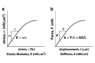
Ever wondered why some materials bend easily while others remain rigid? This blog dives into the fascinating world of elastic modulus and stiffness, unraveling their crucial roles in engineering. By…
Have you ever wondered what makes a perfect circle? In the world of mechanical engineering, roundness is a crucial concept that affects the performance and longevity of rotating components. This…
In today's fast-paced manufacturing world, efficient deburring is crucial. With numerous methods available, choosing the right one can be daunting. In this blog post, we'll explore various deburring techniques, from…
Have you ever wondered what keeps the world spinning smoothly? The unsung heroes behind the scenes are bearings. These small but mighty components play a crucial role in reducing friction…
Gears are the unsung heroes of the mechanical world, quietly working behind the scenes to keep machines running smoothly. But have you ever wondered what materials these critical components are…
This article explores the top 5 cooling tower manufacturers shaping our world. Learn how these companies innovate to keep industries running smoothly and efficiently. Get ready to uncover the secrets…
Have you ever wondered what keeps our gas systems running smoothly and safely? In this article, we explore top gas regulator manufacturers, uncovering their innovations and contributions to the industry.…
Ever wondered why connecting copper and aluminum wires is problematic? This article explains the risks associated with connecting these two metals due to their differing electrochemical properties, which can lead…