Bend Allowance Formula: Calculator & Charts
Have you ever wondered how to precisely calculate the bending allowance for your metal fabrication projects? In this blog post, we'll explore the fascinating world of bend allowance formulas and…
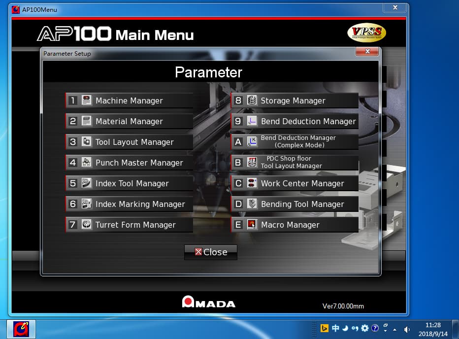
Ever wondered how to streamline your AP100 programming and typesetting processes? This article breaks down essential techniques for optimizing die selection, cutting layouts, and node placement. You’ll learn practical tips for efficient programming, minimizing material waste, and improving the overall quality of your metalworking projects. Dive in to enhance your workflow and achieve more precise results in your manufacturing tasks.

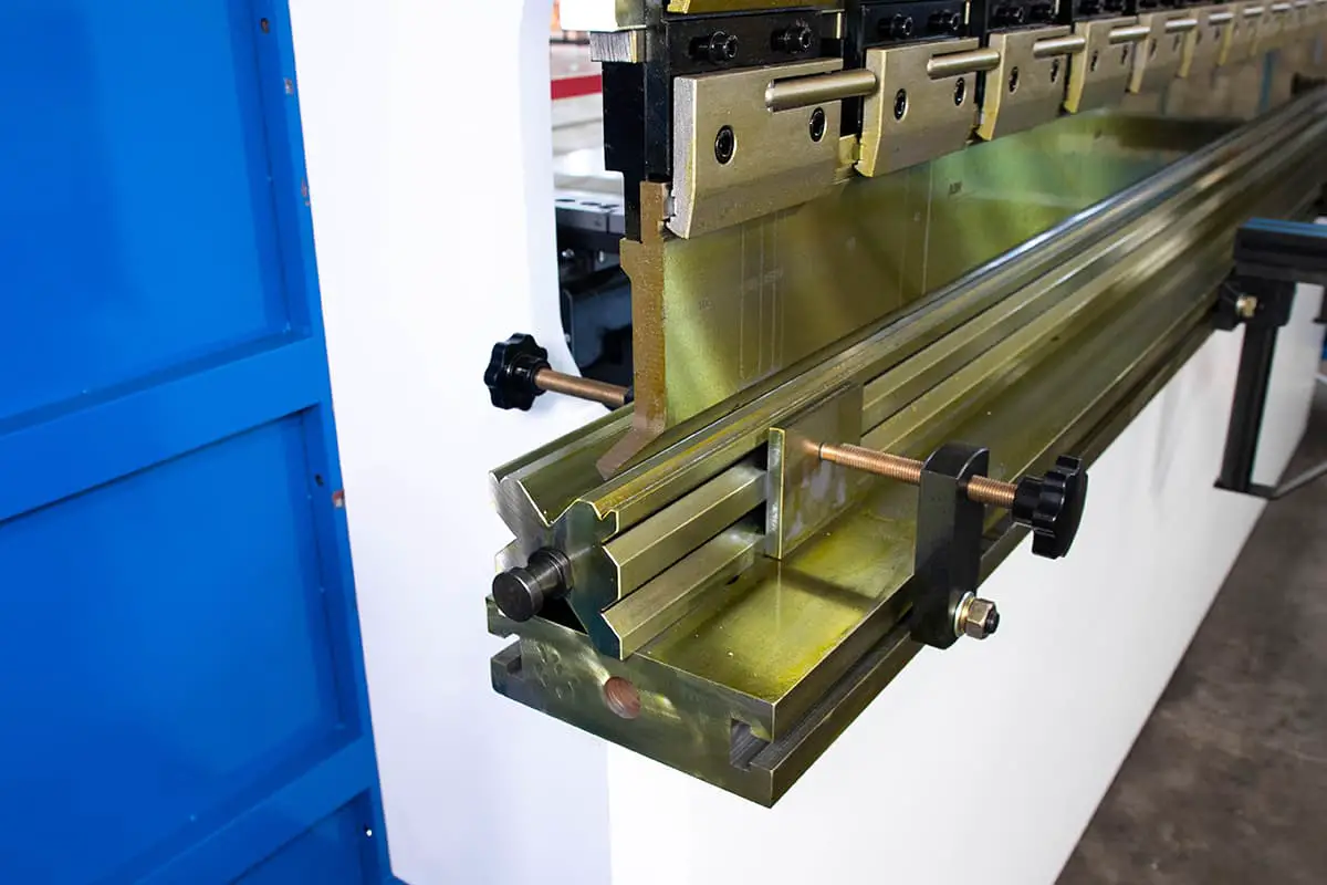
1. Familiarization with common and specialized die shapes:
Knowing the available dies makes programming more convenient and efficient.
2. Rational application of die clearances:
Previously, the standard clearances were 0.1 times the plate thickness for aluminum and copper, 0.15 times for iron, and 0.2 times for stainless steel. Now, AMADA proposes a new die clearance standard for hydraulic punch presses (all three of our factory’s presses are hydraulic).
The die clearance can be appropriately increased by 0.05 times the plate thickness based on the original standard.
This is because hydraulic punch presses have a slower instantaneous cutting speed, and increasing the die clearance will not affect the appearance of the cut section while preventing material from skipping during the cutting process.
3. Die cutting quantity:
During the cutting layout process, it is essential to calculate the cutting amount of each die strike. Generally, the length of material cut by the die should not be less than 2/3 of the die length; otherwise, there may be remnants left.
Rectangular shapes are prone to remnants, mainly at the four right angles, while circular shapes are the least likely to have remnants. Therefore, it is crucial to pay attention to the punching sequence during the cutting layout process.
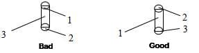
In the example above, Figure 1 shows that punching the circular shape first and the square shape afterward can easily cause the four corners of the square shape to crack. If the punching sequence is changed to that in Figure 2, the wear on the die will be much less.
During the cutting layout process, it is essential to use the longer edge of the die for cutting the edges, as shown in the following example:

4. Length calculation in programming:
(1) On true line cutting:
When cutting edges continuously, the internal program of the machine itself will calculate this edge by dividing the total length of the cut edge minus the length of the first cut, rather than the total length divided by the blade length as we might imagine.
It is essential to note that when the punch press cuts edges continuously, it does not precisely connect each cut to the next. Instead, the punch press automatically defaults to a 0.2mm overlap between the two cuts. We must pay attention to this when calculating.
For example, when cutting a 240mm edge with an RE80x5 rectangular blade, we might think that precisely three cuts are needed.
However, if using on true line cutting, four cuts will be made in reality, which significantly affects die wear and service life.
There are two solutions to this: first, we can use a single-blade approach, cutting one at a time; second, based on the actual situation, we can leave a 0.4mm node on the first cut.
(2) Nibbling:
Not all round or square dies can be used for nibbling. In our factory, we use φ10, φ11, φ12 round dies and RE6x3 square dies for nibbling. It is better not to use other dies for nibbling, especially smaller ones. Nibbling is only suitable for thin plates, as it causes rapid wear on dies when used on thick plates.
When using a round die for nibbling a circle, first punch the center with a larger round die and then proceed with nibbling. Do not leave any nodes. When nibbling with a square die, it is best to leave three evenly spaced, smaller nodes along the circumference.
5. Leaving nodes
During the programming process, nodes should not be left too large or too small; also, they should not be left too many or too few. If the nodes are too large, the product will be difficult to remove or become deformed after removal. If the nodes are too small, the product may fall off.
What is the most appropriate size for nodes?
There is no definite standard; it depends on the actual situation. The ideal node size is one where the product will not fall off during the punching process and will detach from the material due to its weight when the operator pulls the sheet from the worktable.
Here are some reference values for your consideration:
| Metals | <1.0 | 1.0-1.6 | 1.6-2.5 | 2.5-3.0 | ||||
|---|---|---|---|---|---|---|---|---|
| Corner nodes | Middle nodes | Corner nodes | Middle nodes | Corner nodes | Middle nodes | Corner nodes | Middle nodes | |
| Aluminum, Copper | 0.35 | 0.4 | 0.4 | 0.5 | 0.5 | 0.5 | 0.5 | 0.6 |
| Iron | 0.3 | 0.4 | 0.4 | 0.4 | 0.4 | 0.5 | 0.4 | 0.5 |
| Stainless Steel | 0.3 | 0.35 | 0.3 | 0.35 | 0.4 | 0.4 | 0.4 | 0.4 |
The above are some reference values for leaving nodes on common plate thicknesses, but the actual values depend on the specific situation. As for how many nodes are appropriate, generally, we should leave one node between every 350-400mm. For example, if there is a 50x1200mm rectangular unfolded diagram, we can divide it into three sections and leave two nodes in the middle. Try to leave nodes symmetrically on the product to maintain balanced stress.
Note: During the typesetting process, nodes should be appropriately added at certain points.
Place different products of the same material and plate thickness on a single sheet for one-time processing to achieve material, time, and effort savings.
These are some common sheet material specifications. Custom specifications can be ordered based on the unfolded product size requirements.
There are several common issues in programming typesetting:
a) Material itself: For soft and light materials, such as aluminum plates, embossing can easily occur during the punching process. Due to the light weight of the aluminum plate, the cutting waste itself is very light at the same punching speed, and when the waste has not yet completely fallen off, it is lifted by the upper die, and embossing occurs when the waste is pressed onto the plate during the next cut.
b) Punching speed: During the cutting process, if the speed is too fast and the waste has not yet completely fallen off, the upper die lifts the waste, and embossing occurs when the waste is pressed onto the plate during the next cut.
c) Insufficient cutting amount: During the punching process, if the cutting amount is less than 2/3, the die may lift the waste.
a) Insufficient depth of the upper die: If the material is not completely punched through, the upper die is likely to drag the material when it lifts.
b) Unreasonable die clearance: If the lower die clearance is too small, it is easy to jam the material, and the plate is likely to drag the material during movement.
c) Die cutting edge not sharp: If the material is not completely punched through, the upper die is likely to drag the material when it lifts.
d) Press punching speed: If the speed is too fast and the material is not completely cut or dropped, it can cause the material to be dragged.
e) Insufficient ejection force: The spring pressure is not enough.
f) Misaligned punch, uneven force distribution.
a) Insufficient cutting amount: When it is less than 2/3 of the die length, residual die may occur.
b) During erosion, if the pitch is too small, severe residual die is likely. Adjust the pitch appropriately according to actual requirements.
a) Nodes are too small, too few, or not placed reasonably.
When the plate moves, the half-drawing is scratched within the knife disc. When the half-drawing moves in the knife disc, it gets stuck in the lower die. When the plate moves, the half-drawing is forcibly dragged out, causing material displacement and leading to other half-drawings being displaced.
To avoid these issues, consider the factors causing these problems and take into account programming and on-site operation to solve problems more quickly and accurately.

As the founder of MachineMFG, I have dedicated over a decade of my career to the metalworking industry. My extensive experience has allowed me to become an expert in the fields of sheet metal fabrication, machining, mechanical engineering, and machine tools for metals. I am constantly thinking, reading, and writing about these subjects, constantly striving to stay at the forefront of my field. Let my knowledge and expertise be an asset to your business.