Bend Allowance Calculator (Online & Free)
Have you ever struggled with calculating the right bend allowance for your sheet metal projects? In this blog post, we'll dive into the world of bend allowances and explore how…
Have you ever wondered how to precisely calculate the bending allowance for your metal fabrication projects? In this blog post, we’ll explore the fascinating world of bend allowance formulas and calculations. As an experienced mechanical engineer, I’ll guide you through the key concepts and provide practical insights to help you master this crucial aspect of sheet metal design. Get ready to dive in and unlock the secrets of creating accurate and efficient bends in your projects!

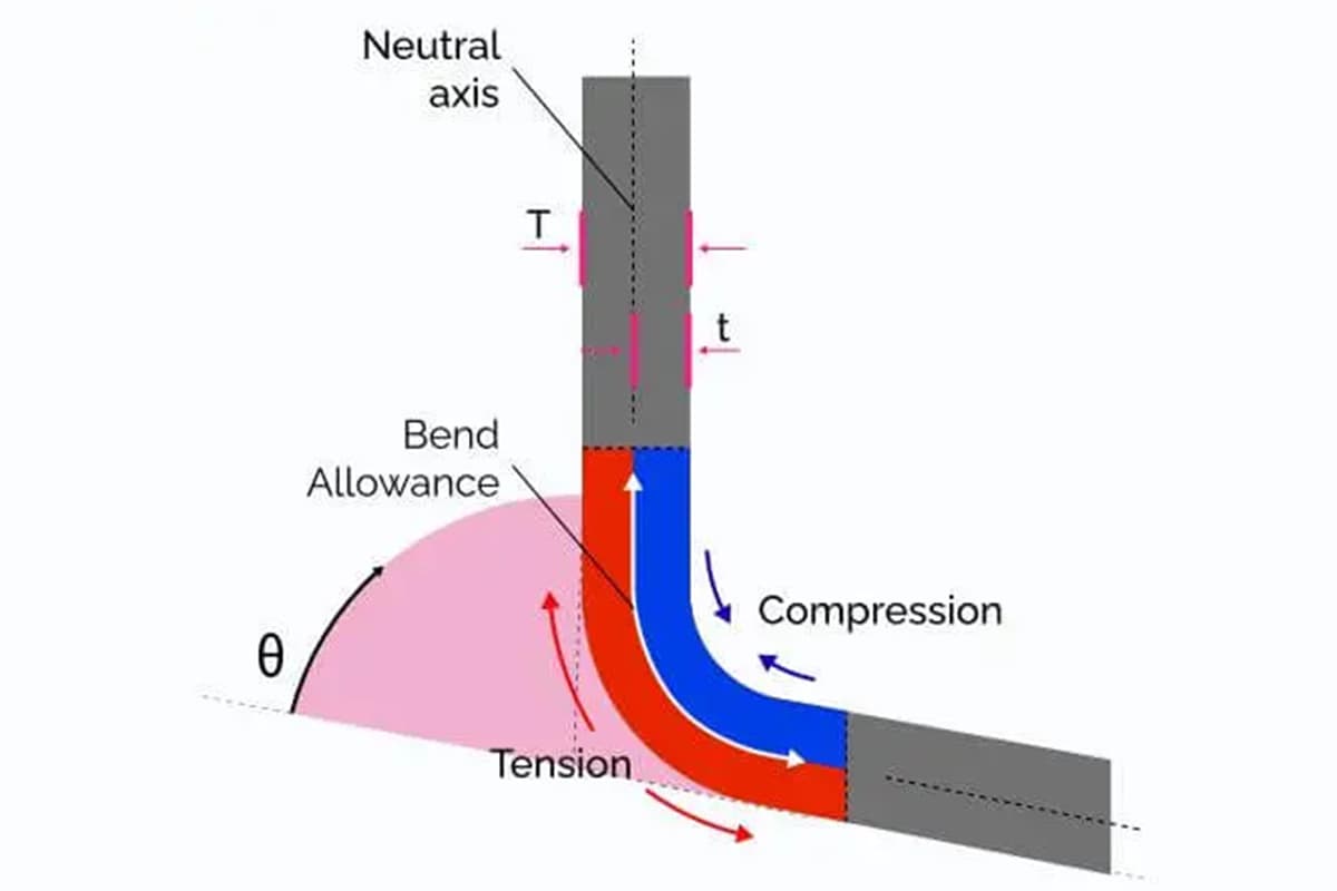
Bend allowance is a critical concept in the field of sheet metal fabrication, particularly when working with bending operations. It refers to the additional length of material required to accommodate the bend in the metal sheet. Understanding and accurately calculating bend allowance is essential for ensuring that the final dimensions of the bent part meet the design specifications.
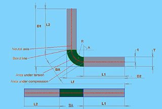
The concept of bending allowance is as follows: when a sheet of metal is bent, it has three dimensions – two outer dimensions (L1 and L2) and one thickness dimension (T).
It is important to note that the sum of L1 and L2 is greater than the unfolded length (L), and the difference between the two is known as the bending allowance (K).
Hence, the unfolded length of a bend can be calculated as L = L1 + L2 – K.
Related reading:
How was the formula for bend allowance created? And how do you calculate bend allowance?
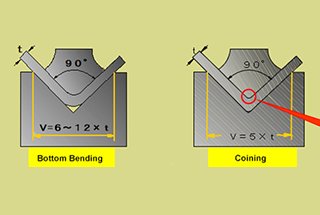
Bend allowance is dependent on the inside formed radius. The lower V die opening determines the inside radius (I.R.) of a formed part. The inside radius for mild steel is 5/32 x lower V die opening (W) when the punch radius is less than 5/32 x W.
If I.R.< Material Thickness (t)
If I.R.> 2 x Material Thickness (t)
Where A= (180 – Bend Included Angle)
If the inside radius is equal to t or 2t, or between t and 2t, the bend allowance is calculated by interpolating the bend allowance values from the two formulas mentioned above.
Besides, to calculate this bending allowance, you can also use the following formula:
This formula considers the diverse geometries and properties of the parts to be formed.
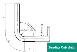
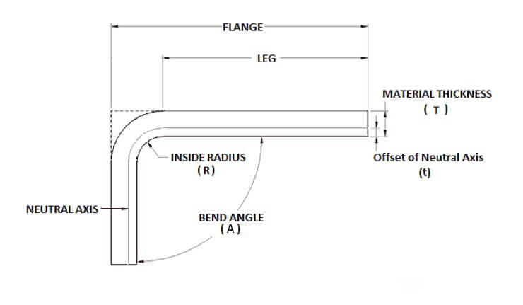
The material thickness (T), bending angle (A), inner bending radius (R), and K-factor of the material to be bent are the most critical factors in this calculation.
As evident from the above formula, calculating the bending allowance is a simple process.
You can determine the bending allowance by substituting the aforementioned values into the formula.
When the bending angle is 90°, the bending allowance formula can be simplified as follows:
Note: The K-factor for most standard materials and thicknesses typically falls between 0 and 0.5.
You can accurately calculate the value of the K-factor using the following K-factor calculator:
Bend allowance is a critical factor in the sheet metal bending process, particularly for materials like aluminum. It accounts for the material stretch that occurs during bending, ensuring accurate final dimensions. Here, we will discuss the specific formula used for aluminum plates and its application.
The bending allowance for an aluminum plate can be calculated using the following formula:𝐿=𝐿1+𝐿2−1.6𝑇
Where:
The value 1.6𝑇 is derived empirically, meaning it has been established through practical experimentation and production experience. This factor accounts for the material’s behavior during bending, ensuring that the final dimensions are accurate.
It’s crucial to note that this formula is specifically applicable under certain conditions:
To determine the expanded size of the aluminum plate, follow these steps:
This calculation will give you the flat pattern length required before bending, ensuring that the final bent part has the correct dimensions.
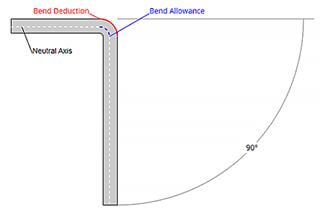
The bending allowance calculator provided below simplifies the process of calculating the bending allowance value, which is crucial for accurate sheet metal fabrication. Bend allowance is the length of the neutral axis between the bend lines, which helps in determining the correct blank size for a bent part.
The bend allowance chart is an essential resource for professionals working with sheet metal fabrication. It provides a comprehensive listing of key parameters such as material thickness, bending radius, bending angle, bend allowance, and bend deduction values for common materials. This information is crucial for accurately calculating the development length of a sheet metal part after bending.
Further reading:
| TV | Angle | 0.6 | 0.8 | 1 | 1.2 | 1.5 | 2 | 2.5 | 3 | 3.5 | 4 | 4.5 | 5 | Shortest size |
| V4 | 90 | 0.9 | 1.4 | 2.8 | ||||||||||
| V4 | 120 | 0.7 | ||||||||||||
| V4 | 150 | 0.2 | ||||||||||||
| V6 | 90 | 1.5 | 1.7 | 2.15 | 4.5 | |||||||||
| V6 | 120 | 0.7 | 0.86 | 1 | ||||||||||
| V6 | 150 | 0.2 | 0.3 | 0.4 | ||||||||||
| V7 | 90 | 1.6 | 1.8 | 2.1 | 2.4 | 5 | ||||||||
| V7 | 120 | 0.8 | 0.9 | 1 | ||||||||||
| V7 | 150 | 0.3 | 0.3 | 0.3 | ||||||||||
| V8 | 90 | 1.6 | 1.9 | 2.2 | 2.5 | 5.5 | ||||||||
| V8 | 30 | 0.3 | 0.34 | 0.4 | 0.5 | |||||||||
| V8 | 45 | 0.6 | 0.7 | 0.8 | 1 | |||||||||
| V8 | 60 | 1 | 1.1 | 1.3 | 1.5 | |||||||||
| V8 | 120 | 0.8 | 0.9 | 1.1 | 1.3 | |||||||||
| V8 | 150 | 0.3 | 0.3 | 0.2 | 0.5 | |||||||||
| V10 | 90 | 2.7 | 3.2 | 7 | ||||||||||
| V10 | 120 | 1.3 | 1.6 | |||||||||||
| V10 | 150 | 0.5 | 0.5 | |||||||||||
| V12 | 90 | 2.8 | 3.65 | 4.5 | 8.5 | |||||||||
| V12 | 30 | 0.5 | 0.6 | 0.7 | ||||||||||
| V12 | 45 | 1 | 1.3 | 1.5 | ||||||||||
| V12 | 60 | 1.7 | 2 | 2.4 | ||||||||||
| V12 | 120 | 1.4 | 1.7 | 2 | ||||||||||
| V12 | 150 | 0.5 | 0.6 | 0.7 | ||||||||||
| V14 | 90 | 4.3 | 10 | |||||||||||
| V14 | 120 | 2.1 | ||||||||||||
| V14 | 150 | 0.7 | ||||||||||||
| V16 | 90 | 4.5 | 5 | 11 | ||||||||||
| V16 | 120 | 2.2 | ||||||||||||
| V16 | 150 | 0.8 | ||||||||||||
| V18 | 90 | 4.6 | 13 | |||||||||||
| V18 | 120 | 2.3 | ||||||||||||
| V18 | 150 | 0.8 | ||||||||||||
| V20 | 90 | 4.8 | 5.1 | 6.6 | 14 | |||||||||
| V20 | 120 | 2.3 | 3.3 | |||||||||||
| V20 | 150 | 0.8 | 1.1 | |||||||||||
| V25 | 90 | 5.7 | 6.4 | 7 | 17.5 | |||||||||
| V25 | 120 | 2.8 | 3.1 | 3.4 | ||||||||||
| V25 | 150 | 1 | 1 | 1.2 | ||||||||||
| V32 | 90 | 7.5 | 8.2 | 22 | ||||||||||
| V32 | 120 | 4 | ||||||||||||
| V32 | 150 | 1.4 | ||||||||||||
| V40 | 90 | 8.7 | 9.4 | 28 | ||||||||||
| V40 | 120 | 4.3 | 4.6 | |||||||||||
| V40 | 150 | 1.5 | 1.6 |
| TV | Angle | 0.6 | 0.8 | 1 | 1.2 | 1.5 | 2 | 2.5 | 3 | 3.5 | 4 | 4.5 | 5 | Shortest size |
| V4 | 1.4 | 2.8 | ||||||||||||
| V6 | 1.6 | 4.5 | ||||||||||||
| V7 | 1.6 | 1.8 | 5 | |||||||||||
| V8 | 1.8 | 2.4 | 3.1 | 5.5 | ||||||||||
| V10 | 2.4 | 3.2 | 7 | |||||||||||
| V12 | 2.4 | 3.2 | 8.5 | |||||||||||
| V14 | 3.2 | 10 | ||||||||||||
| V16 | 3.2 | 4 | 4.8 | 11 | ||||||||||
| V18 | 4.8 | 13 | ||||||||||||
| V20 | 4.8 | 14 | ||||||||||||
| V25 | 4.8 | 5.4 | 6 | 17.5 | ||||||||||
| V32 | 6.3 | 6.9 | 22 |
| Angle | 0.6 | 0.8 | 1 | 1.2 | 1.5 | 2 | 2.5 | 3 | 3.5 | 4 | 4.5 | 5 | Shortest size |
| 90 | 3.6 | 5.2 | 6.8 | 8.4 | 28 | ||||||||
| 120 | |||||||||||||
| 150 |
| MATERIAL | SPCC | SUS | Al (LY12) | SECC | ||||
|---|---|---|---|---|---|---|---|---|
| T | ΔT | ΔK | ΔT | ΔK | ΔT | ΔK | ΔT | ΔK |
| T=0.6 | 1.25 | 1.26 | ||||||
| T=0.8 | 0.18 | 1.42 | 0.15 | 1.45 | 0.09 | 1.51 | ||
| T=1.0 | 0.25 | 1.75 | 0.20 | 1.80 | 0.30 | 1.70 | 0.38 | 1.62 |
| T=1.2 | 0.45 | 1.95 | 0.25 | 2.15 | 0.50 | 1.90 | 0.43 | 1.97 |
| T=1.4 | 0.64 | 2.16 | ||||||
| T=1.5 | 0.64 | 2.36 | 0.50 | 2.50 | 0.70 | 2.30 | ||
| T=1.6 | 0.69 | 2.51 | ||||||
| T=1.8 | 0.65 | 3.00 | ||||||
| T=1.9 | 0.60 | 3.20 | ||||||
| T=2.0 | 0.65 | 3.35 | 0.50 | 3.50 | 0.97 | 3.03 | 0.81 | 3.19 |
| T=2.5 | 0.80 | 4.20 | 0.85 | 4.15 | 1.38 | 3.62 | ||
| T=3.0 | 1.00 | 5.00 | 5.20 | 1.40 | 4.60 | |||
| T=3.2 | 1.29 | 5.11 | ||||||
| T=4.0 | 1.20 | 6.80 | 1.00 | 7.00 | ||||
| T=5.0 | 2.20 | 7.80 | 2.20 | 7.80 | ||||
| T=6.0 | 2.20 | 9.80 | ||||||
Note:
A well-maintained bend allowance chart is a vital tool in the sheet metal fabrication industry. It ensures precision and efficiency in the bending process, ultimately leading to higher quality and more accurate finished products. By understanding and utilizing the values provided in the chart, engineers and fabricators can achieve optimal results in their projects.

As the founder of MachineMFG, I have dedicated over a decade of my career to the metalworking industry. My extensive experience has allowed me to become an expert in the fields of sheet metal fabrication, machining, mechanical engineering, and machine tools for metals. I am constantly thinking, reading, and writing about these subjects, constantly striving to stay at the forefront of my field. Let my knowledge and expertise be an asset to your business.