Selecting the Right Press Brake Toolings: Guide and Standards
How do you ensure precision in your metal bending operations? Choosing the right press brake tooling is crucial. This guide delves into the selection of die molds and punches, offering insights into various types of toolings like four-way dies and adjustable dies. Learn how to enhance production efficiency, reduce wear and tear, and select the best tooling for your specific bending needs. Unlock the secrets to optimal press brake performance and maximize your tooling’s service life.
To guide bending personnel in the more rational selection of die molds, improve the service life of the molds, and reduce abnormal wear and tear.
2. Function
To shorten the time required for selecting bending die molds, enhance production efficiency, and lower costs.
3. Scope of Application
Sheet metal bending operations.
4. Press Brake Tooling Basics
General Purpose
General purpose tooling is manufactured from pre-hardened tool steel with a Rockwell hardness range of Rc 28-30.
Tooling usually covers the full length of the press brake bed, with nominal tolerances on size and straightness depending on the tooling manufacturer.
General purpose tooling that is sectionalized must be match marked since the individual sections may not be interchangeable, due to variance in dimensional manufacturing tolerances.
General Purpose Flame Hardened
Several press brake tooling manufacturers offer flame hardened tooling for better wear resistance at the die shoulders and punch tip radius.
This tooling can be less accurate in straightness, due to the heat treating process and subsequent mechanical straightening.
General Purpose Four Way Dies
Four Way Die
The four way die has four different female “V” openings, each of which is accessed by rotating the die.
The disadvantage of this configuration is that the minimum flange of a part to be formed cannot be smaller than the width of the four way die.
Although the female opening change is simple, the die and die holder should be centered with the punch for each rotation, to ensure optimum press brake forming performance.
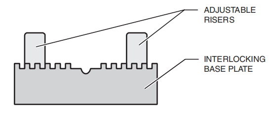
Adjustable Dies
Adjustable dies provide a range of openings – in 1/2” increments from a minimum of 1” to a maximum of 8”, 10” or 12”. An opening is set by moving keyed adjustable risers to a keyway position of the interlocking base plate.
Adjustable Die
This type of die is useful for forming a greater range of material thicknesses. It is especially favorable because the wider openings allow forming of thicker plate.
Punches
A variety of punches are available for different forming techniques. Consult tooling documentation for information on specific applications.
Punch
Precision Ground and Hardened Dies
Precision ground and hardened tooling is manufactured in sections to close dimensional tolerances to allow interchanging and direct replacement.
Precision tooling is geometrically defined with specified die height, die opening and shoulder radius, punch radius and load rating-all of which can be catalogued to a press brake CNC gauging system tool library.
Defining the geometric tooling parameters in a CNC environment enhances press brake productivity because it reduces the number of trial bends and sample parts required for setting up the job.
Press Brake Die Holders
1. Standard Die Holder:
Standard Die Holder
The standard die holder serves as a filler block between the press brake bed and the press ram to ensure die closure within the full stroke of the press brake. In most instances, the tooling alone will not fill the shut height.
The die holder also serves as a working surface to minimize wear to the press brake bed during die changes.
The die holder permits the die set to be lifted for localized shimming to accommodate formed part angle variances. These variances are due to irregularities in general purpose dies and to wear, usually associated with continuous press braking in the same area.
Die holders may be restrained from movement or are mechanically adjusted on the press brake bed by a tang and set screws, T-bolt fasteners or die adjuster blocks.
2. Four Way Die Holder:
Four Way Die Holder
The four way die holder is a channel that retains and centers a four way die with the punch during forming.
The four way die holder is similar to the standard die holder in terms of function and attachment to the press brake.
3. Crownable Die Holder:
Several tooling manufacturers offer crownable die holders with:
single adjustment for proportional die holder crowning over the full length, or
individual adjustment points along the length of the die holder.
An advantage of the crownable die holder is that the operator can make die set adjustments without the traditional die holder shimming procedures.
The attachment and dimensional stack height for the press brake shut height are similar to the standard die holder.
5. Press Brake Tooling Selection
4.1 Commonly used top punch include: 88° straight punch (R1), 30° acute punch/straight acute punch (R1/R0.5), 88° gooseneck punch (R1), 88° straight gooseneck punch (R1/R0.5), flattening punch, and specialized upper die molds.
4.2 Commonly used lower die for bending include: single/double V lower molds with angles of 30° and 88°, V4, V6, V7, V8, V10, V12, V16, and V25 (mm).
4.3 The selection of bending die is generally based on the arrangement of the bending blade sequence after reviewing the drawings.
4.4 Selecting the upper die according to the angle:
4.4.1 When the processing angle is greater than or equal to 88°, use an upper die with an angle less than 88° (e.g., straight blade, sharp blade/straight sharp blade, curved blade, straight curved blade, etc.).
4.4.2 When the processing angle is less than 88°, use a 30° upper die (e.g., sharp blade/straight sharp blade).
4.4.3 When it is necessary to press a dead edge, use a sharp blade/straight sharp blade to form an acute angle (generally 30°), and then use a flattening mold to flatten the pressed edge.
4.4.4 When the plate thickness exceeds 3mm, avoid using sharp blades/straight sharp blades to prevent tool damage.
4.5 When it is necessary to process a U-shape based on the external shape requirements.
When b-a ≥ 5mm, you can choose from acute punch (straight sharp blade), straight punch (straight blade), straight gooseneck punch (straight curved blade), or gooseneck punch (curved blade).
When 1mm < b-a < 5mm, you can choose from straight gooseneck punch (straight curved blade) or gooseneck punch (curved blade). When b-a < 1mm, you can choose gooseneck punch (curved blade).
Note: Both a and b > 6mm and 100mm > a, b are internal dimensions. When you need to process a Z-shape, you typically choose from straight punch (straight blade), acute punch (sharp blade/straight sharp blade), straight gooseneck punch (straight curved blade), and gooseneck punch (curved blade).
4.6 Lower die selection:
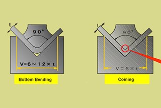
4.6.1 The size of the V-groove is generally chosen based on six times the thickness of the plate.
4.6.2 Select the lower die according to the angle: when the angle is greater than or equal to 88°, you can choose from 88° or 30° lower dies; when the angle is less than 88°, choose a 30° lower die (measure the effective height of the upper die mold: the distance from the upper die mold to the blade edge on the force-receiving surface of the upper die clamp).
4.7 When splicing upper and lower dies, the following points should be considered:
4.7.1 Do not mix molds with different heights during selection, as this may cause poor angles, damage to the die molds, or even cause work-related accidents.
4.7.2 When selecting an upper die mold for a hemming door panel, consider product processing quality and ease of handling, generally leaving a gap of 3-6mm at both ends (if necessary, consider using an “edge blade”).
4.7.3 Avoid using damaged molds for product processing to prevent poor appearance, and inspect the linearity and flatness of the upper die mold’s cutting edge after installation.
4.7.4 When avoiding positions, be aware of appearance quality issues such as indentation at the avoidance point and insufficient angles.
4.8 Die mold selection under abnormal conditions:
4.8.1 For pressing lines, choose a pressure-resistant sharp blade for the upper die mold and a flat, aligned lower die mold with no steps between upper and lower die molds.
4.8.2 When processing U-shapes, if the inner dimension of the opening is less than 6mm, first use a curved blade to bend the opening larger than the second blade size, then press flat to ensure the dimension or use a specialized mold for shaping.
4.8.3 When processing products with specific requirements for the internal R radius, consider a matching R-radius upper die mold in advance when selecting the upper die mold (e.g., internal R radius requirements of R0.3, R1, R4, R8, or R10).
4.8.4 When bending 6mm with a 2.0mm plate thickness, choose an 88° V8 lower die mold; when bending 10mm with a 3.0mm plate thickness, choose an 88° V12 lower die mold to prevent workpieces from slipping and becoming unprocessable due to excessively small processing dimensions.
4.8.5 When processing round steel, use specialized die molds and have a dedicated operator.
4.9 When selecting top punch/bottom die molds, try to avoid splicing to prevent splicing marks and maintain a good product appearance.
4.10 When calibrating top/bottom die molds, use molds that are greater than or equal to 300mm for calibration. Do not use spliced small molds or molds smaller than 300mm for calibration. For molds over 1m in length, the length difference between the top and bottom die molds should not exceed 20%.
4.11 Before installing the die mold, make sure to check whether the machine’s limited travel is greater than the total height of the top/bottom die molds to prevent mold damage and work-related accidents.
4.12 Check whether the mold is locked before calibration, and check the mold’s tightness again after calibration.
4.13 Do not place unused die molds on the equipment to prevent molds from falling, causing damage or injury.
4.14 After using the die mold, promptly return it to the designated mold rack and place it neatly.
4.15 Do not install two different height die molds on the equipment at the same time.
4.16 The workshop should regularly maintain and service the die molds and clearly mark them.
As the founder of MachineMFG, I have dedicated over a decade of my career to the metalworking industry. My extensive experience has allowed me to become an expert in the fields of sheet metal fabrication, machining, mechanical engineering, and machine tools for metals. I am constantly thinking, reading, and writing about these subjects, constantly striving to stay at the forefront of my field. Let my knowledge and expertise be an asset to your business.
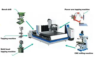
Struggling with inefficiencies and high costs in sheet metal fabrication? Discover how automated equipment can revolutionize your processes, saving both time and money. This article guides you through selecting the…
Attention all mechanics and engineering enthusiasts! Have you ever wondered about the ins and outs of operating a press brake machine? In this blog post, we'll dive into the world…
Have you ever considered the forces at play when bending a pipe? In this article, we'll explore the fascinating world of pipe bending mechanics. Our expert mechanical engineer will break…
Have you ever struggled with sheet metal bending problems that left you scratching your head? In this insightful blog post, an experienced mechanical engineer shares their expertise on tackling common…
In the vast world of manufacturing, one machine stands tall: the press brake. With its ability to bend and shape metal with precision and power, it has become an indispensable…
How does a machine achieve high precision and efficiency in metal bending? Discover the secrets behind the Electro-Hydraulic Servo Press Brake. This article delves into the intricate mechanics, setup procedures,…
Have you ever wondered what makes press brake dies so fascinating? In this captivating blog post, we'll delve into the intricate world of these essential tools that shape the metal…
Have you ever wondered how a simple sheet of metal transforms into a complex, three-dimensional object? Press brake bending, a crucial process in metal fabrication, holds the key to this…
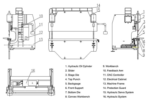
Have you ever wondered how a press brake shapes metal with such precision? This article unveils the fascinating parts and functions of a press brake, showing you its essential role…