How Alloy Casting Properties Affect Your Castings?
Why do some castings fail while others excel? The answer lies in the properties of alloy casting. This article explores how factors like fluidity, shrinkage, oxidability, and gas absorption impact the quality and performance of casted parts. By understanding these properties, you’ll gain insights into selecting the right materials and designing processes that ensure high-quality castings. Dive in to learn how mastering these elements can elevate your casting projects and prevent common defects.
Concept of Alloy Casting Performance: Casting performance refers to the capability of an alloy to be cast and yield high-quality castings.
Indicators of Alloy Casting Performance: Filling ability (fluidity), shrinkage, oxidability, segregation, and gas absorption, etc.
The quality of alloy casting performance significantly impacts the casting process, casting quality, and casting structure design.
Therefore, when choosing materials for casting parts, materials with good casting performance should be preferred while ensuring operational performance.
However, in actual production, to ensure operational performance, alloys with poorer casting performance are often used.
In these cases, more attention should be given to the design of the casting structure and appropriate casting process conditions should be provided to produce high-quality castings. Thus, a comprehensive understanding of an alloy’s casting performance is necessary.
I. Casting Performance of Alloys – Filling Ability of Alloys
01 Definition of Alloy Filling Ability
Definition: The ability of the molten alloy to fill the mold and yield a casting with correct dimensions and clear contours is called the filling ability of the molten alloy.
The filling process of the molten alloy is the first stage of casting formation. This stage involves a series of physical and chemical changes, such as the flow of the molten alloy and heat exchange between it and the mold, along with the crystallization of the alloy.
Therefore, the filling ability not only depends on the flowability of the alloy itself but is also influenced by external conditions like mold properties, pouring conditions, and the structure of the casting.
02 Impact on Casting Quality
Impact on Casting Quality: If the filling ability of the molten alloy is strong, it becomes easier to obtain thin-walled and complex castings. This results in fewer defects such as unclear contours, insufficient pouring, and cold shut.
It also facilitates the rise and expulsion of gases and non-metallic inclusions in the molten metal, reducing defects such as pores and slag inclusions. Furthermore, it can enhance the feeding ability, thereby decreasing the tendency for shrinkage and porosity.
03 Factors Affecting the Filling Ability of Alloys and Technological Countermeasures
(1) Alloy Fluidity
Definition:
Fluidity refers to the ability of molten alloy to flow. It is an inherent property of an alloy, depending on the type of alloy, crystallization characteristics, and other physical properties (for instance, the smaller the viscosity and the larger the heat capacity, the smaller the thermal conductivity and the larger the latent heat of crystallization, and the smaller the surface tension, the better the fluidity).
Measurement Method:
To compare the fluidity of different alloys, the standard spiral sample casting method is often used. The length of the fluidity sample obtained under the same mold (generally using a sand mold) and casting conditions (such as the same pouring temperature or the same overheating temperature) can represent the fluidity of the tested alloy.
Among common casting alloys, gray cast iron and silicon brass have the best fluidity, while cast steel has the worst. For the same alloy, fluidity samples can also be used to study the impact of various casting process factors on its filling ability.
The length of the obtained fluidity sample is the product of the time and flow speed of the molten metal from the start of pouring to the stop of flow. Therefore, any factors that affect these two factors will impact fluidity (or filling ability).
The chemical composition of the alloy determines its crystallization characteristics, and the crystallization characteristics dominate the impact on fluidity. Alloys with eutectic components (such as iron-carbon alloys with a mass fraction of carbon of 4.3%) solidify at a constant temperature, the inner surface of the solidification layer is relatively smooth, and the flow resistance to the subsequent molten metal is small.
Besides, the solidification temperature of the eutectic component alloy is low, which is easy to obtain a larger degree of overheating, so the fluidity is good. Apart from eutectic alloys and pure metals, other component alloys solidify within a certain temperature range, and there is a two-phase zone of liquid and solid in the casting section.
The first formed dendritic crystals create a larger flow resistance for the subsequent molten metal, so the fluidity decreases. The farther the alloy composition deviates from the eutectic component, the larger the solidification temperature range, and the worse the fluidity. Therefore, alloys close to the eutectic composition are often used as casting materials.
(2) Mold Properties
① The heat storage coefficient of the mold represents the ability of the mold to absorb and store heat from the molten metal.
The larger the thermal conductivity, specific heat capacity, and density of the mold material, the stronger its heat storage ability, the stronger the quenching ability on the molten metal, the shorter the time for the molten metal to maintain flow, and the worse the filling ability.
For example, metal mold casting is more likely to produce defects such as insufficient pouring and cold shut than sand mold casting.
② Mold temperature preheating can reduce the temperature difference between it and the molten metal, reduce the intensity of heat exchange, and thereby improve the filling ability of the molten metal.
For instance, when casting aluminum alloy castings with a metal mold, raising the mold temperature from 340°C to 520°C increases the length of the spiral sample from 525mm to 950mm under the same pouring temperature (760°C). Therefore, preheating the mold is one of the necessary process measures in metal mold casting.
③ The gas in the mold has a certain ability to emit gas, which can form a gas film between the molten metal and the mold, reducing the flow resistance and facilitating filling. But if the gas emission is too large and the mold exhaust is not smooth, the back pressure of the gas generated in the mold cavity will hinder the flow of the molten metal.
Therefore, to improve the permeability of the mold (core) sand, it is necessary and often applied to open vent holes in the mold.
(3) Pouring Conditions
① Pouring Temperature
The pouring temperature has a decisive impact on the filling ability of the molten metal. Increasing the pouring temperature lowers the viscosity of the alloy and prolongs the time it remains flowable, thereby enhancing the filling ability; conversely, the filling ability will decrease.
For thin-walled castings or alloys with poor fluidity, increasing the pouring temperature to improve filling ability is often used and relatively convenient in production.
However, as the pouring temperature increases, the alloy’s gas absorption and oxidation become serious, the total shrinkage increases, and defects such as blowholes, shrinkage holes, and sand adhesion easily occur, and the crystalline structure of the casting becomes coarse.
Therefore, in principle, the pouring temperature should be reduced as much as possible while ensuring sufficient fluidity.
② Filling Pressure
The greater the pressure on the molten metal in the direction of flow, the greater the flow rate and the better the filling ability. Therefore, methods such as increasing the height of the sprue or applying artificial pressure (such as pressure casting, low-pressure casting, etc.) are often used to improve the filling ability of molten alloys.
(4) Casting Structure
When the wall thickness of the casting is too small, the wall thickness changes sharply or there is a larger horizontal surface, it will make the filling of the alloy liquid difficult. Therefore, when designing the casting structure, the wall
thickness of the casting must be greater than the minimum allowable value; some castings need to design flow channels; and ribs should be set on large flat surfaces. This not only facilitates the smooth filling of the alloy liquid but also prevents the occurrence of sand inclusion defects.
II. Casting Performance of Alloys – Segregation of Alloys
Segregation
This term refers to the uneven distribution of chemical composition within castings. Segregation can make the properties of castings uneven, and in severe cases, it can lead to defective products.
Segregation can be divided into two categories: Micro-segregation and Macro-segregation.
Micro-segregation:
Intragranular segregation (also known as dendritic segregation) – This is the phenomenon where different parts of the same grain have varying chemical compositions. For alloys that form solid solutions, only under very slow cooling conditions can atoms diffuse sufficiently to obtain chemically homogeneous grains during the crystallization process.
Under actual casting conditions, the solidification rate of the alloy is faster, and atoms do not have enough time to diffuse fully. As a result, the grains that grow in a dendritic manner inevitably have uneven chemical compositions.
To eliminate intragranular segregation, the casting can be reheated to a high temperature and held for a long time to allow for sufficient atom diffusion. This heat treatment method is known as diffusion annealing.
Macro-segregation:
Density Segregation (formerly known as gravity segregation) – This is the phenomenon where the upper and lower parts of the casting have uneven chemical compositions. When the densities of the alloying elements differ significantly, the elements with lower density tend to accumulate at the upper part after the casting solidifies completely, while the elements with higher density tend to accumulate at the bottom.
To prevent density segregation, the molten metal should be stirred thoroughly or cooled rapidly during pouring to prevent the separation of elements with different densities.
There are many types of macro-segregation, including positive segregation, negative segregation, V-shaped segregation, and band segregation, in addition to density segregation.
III. Casting Performance of Alloys – Gas Absorption of Alloys
Gas absorption of alloys – This term refers to the property of alloys to absorb gases during melting and pouring.
The gas absorption of alloys increases with temperature. Gases are much more soluble in molten alloy than in solid state. The higher the superheat of the alloy, the more gas it contains. The presence of gases in castings takes three forms: solid solution, compound, and porosity.
(1) Porosity in Castings
Based on the source of the gas in the alloy, porosity can be divided into three categories:
a. Exudation porosity
When gases dissolved in the alloy liquid exude during the solidification process due to a decrease in gas solubility, and are not able to be expelled in time, the porosity formed in the castings is called exudation porosity.
Exudation porosity is most common in aluminum alloys, with diameters often less than 1mm. It not only affects the mechanical properties of the alloy, but also severely affects the air-tightness of the casting.
b. Invasive porosity
Invasive porosity refers to pores formed by gases gathered on the surface layer of the sand mold that invade the alloy liquid.
c. Reactive porosity
Reactive porosity refers to pores formed in castings by gases produced through chemical reactions between the molten alloy poured into the mold and the moisture, rust, etc. in the mold material, core supports, chillers, or slag.
Reactive porosity comes in many types and shapes. For example, pores created by chemical reactions between the alloy liquid and the sand mold interface are usually distributed 1-2mm under the surface of the casting. After the surface is machined or cleaned, many small holes are exposed, so they are called sub-surface pores.
Pores disrupt the continuity of the alloy, reduce the effective load-bearing area, and cause stress concentration around the pores, thereby reducing the mechanical properties of the castings, especially impact toughness and fatigue strength. Dispersed pores can also promote the formation of microporosity, reducing the air-tightness of the casting.
(2) Measures to Prevent Porosity
a. Reduce the gas emission of the molding sand (core sand) and increase the exhaust capacity of the mold.
b. Control the temperature of the alloy liquid, reduce unnecessary superheating, and reduce the original gas content of the alloy liquid.
c. Apply pressure to solidify the alloy and prevent gas exudation. Changes in pressure directly affect gas exudation. For example, if liquid aluminum alloy is crystallized in a pressure chamber at 405-608 kPa (4-6 atmospheres), a pore-free casting can be obtained.
d. During melting and pouring, try to reduce the chance of alloy liquid contact with gases. For example, apply a cover to protect the surface of the alloy liquid or use vacuum melting technology.
e. De-gas the alloy liquid. For example, introducing chlorine gas into the aluminum alloy liquid. When undissolved chlorine gas bubbles rise, hydrogen atoms dissolved in the aluminum alloy liquid continuously diffuse into the chlorine gas bubbles and are removed from the alloy liquid.
f. The surfaces of chillers, core supports, etc. should not be rusty or oily, and should be kept dry, etc.
IV. Casting Properties of Alloys – Solidification and Shrinkage of Alloys
01 Alloy Solidification and Shrinkage
(1) Definitions of Solidification and Shrinkage
Solidification is the process where a substance transitions from a liquid state to a solid state.
Shrinkage refers to the reduction in volume that occurs in castings during solidification and cooling processes.
(2) Impact on Casting Quality
If solidification and shrinkage are not adequately controlled during the cooling process of the liquid metal poured into the mold, the casting might develop defects such as shrinkage cavities, shrinkage porosity, casting stresses, deformation, and cracks.
02 Solidification Methods of Castings and Influencing Factors
(1) Casting Solidification Methods
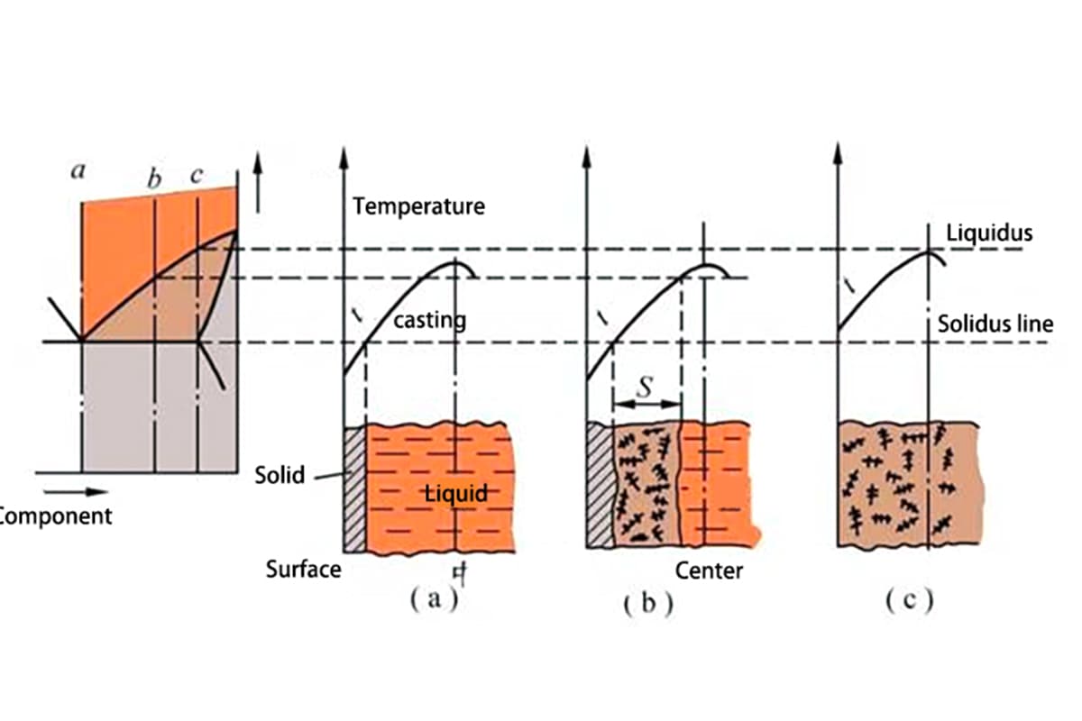
During solidification, three areas typically exist on the cross-section of the casting: the solid phase area, the solidification area, and the liquid phase area. The coexistence of liquid and solid phases in the solidification area significantly influences the quality of the casting.
The “solidification method” of casting is categorized based on the breadth of this solidification area, into the following three types:
Figure 1 Classification of Casting Solidification Areas
① Layer-by-layer Solidification
Pure metals or eutectic alloys solidify without a coexistent liquid and solid phase in the solidification area, as shown in Figure 2(a). Thus, a clear boundary (solidification front) separates the outer solid layer and the inner liquid layer on the cross-section.
As the temperature drops, the solid layer thickens, and the liquid layer reduces until the solidification front reaches the center. This solidification method is called layer-by-layer solidification.
② Paste-like Solidification
If the crystallization temperature range of an alloy is broad, and the temperature distribution curve within the casting is relatively flat, there will be no solid layer on the casting surface during a certain period of solidification.
Instead, the solidification area where liquid and solid phases coexist extends across the entire cross-section, as shown in Figure 1(C). This solidification method is similar to cement solidification, initially paste-like before solidifying, and is thus called paste-like solidification.
③ Intermediate Solidification
The majority of alloys solidify using a method between the above two, referred to as intermediate solidification.
Relationship between Casting Solidification and Casting Defects:
Generally, layer-by-layer solidification facilitates alloy filling and shrinkage compensation, preventing shrinkage cavities and porosity. Achieving dense structural castings can be challenging during paste-like solidification.
(2) Main Factors Influencing Casting Solidification Methods
① Crystallization Temperature Range of the Alloy
A smaller crystallization temperature range of an alloy results in a narrower solidification area and a tendency towards layer-by-layer solidification. For example, during sand casting, low-carbon steel solidifies layer-by-layer, while high-carbon steel, with a broad crystallization temperature range, solidifies in a paste-like manner.
② Temperature Gradient of the Casting Cross-section
Given a specific crystallization temperature range of an alloy, the width of the solidification area depends on the temperature gradient of the casting cross-section, as shown in Figure 2 (T1→T2). If the gradient of the casting temperature increases, the corresponding solidification area narrows.
Figure 2 Casting Solidification Methods
The temperature gradient of a casting mainly depends on:
a. Alloy Properties: The lower the solidification temperature of an alloy, the higher its thermal conductivity, and the greater its latent heat of crystallization, the better its ability to equalize internal temperatures, resulting in a smaller temperature gradient (as in most aluminum alloys).
b. Heat Retention Capacity of the Mold: A higher heat retention coefficient of the mold increases its rapid cooling ability, leading to a greater casting temperature gradient.
c. Pouring Temperature: A higher pouring temperature introduces more heat into the mold, reducing the casting’s temperature gradient.
d. Casting Wall Thickness: Thicker casting walls result in a smaller temperature gradient.
From the above discussion, it can be concluded that alloys tending towards layer-by-layer solidification (such as gray cast iron, aluminum-silicon alloys, etc.) are more suitable for casting and should be used where possible.
When alloys tending towards paste-like solidification (such as tin bronze, aluminum copper alloy, ductile iron, etc.) must be used, appropriate process measures (for example, metal mold casting) should be considered to reduce their solidification area.
03 Alloy Shrinkage and Its Influencing Factors
(1) Principle and Process of Alloy Shrinkage
The structure of a liquid alloy consists of atomic clusters and “voids”. The atoms within the clusters are orderly arranged, but the distance between the atoms is larger than in the solid state. When the liquid alloy is poured into the mold, the temperature continues to fall, voids decrease, atomic distances shorten, and the volume of the alloy liquid decreases.
As the alloy liquid solidifies, the voids disappear, and the atomic distances further shorten. During the process of cooling to room temperature after solidification, the atomic distances continue to decrease.
The shrinkage of an alloy from the pouring temperature to room temperature undergoes the following three stages:
①Liquid Shrinkage
This is the shrinkage of the alloy from the pouring temperature to the beginning of solidification (liquidus line temperature), while the alloy is in a liquid state. It results in a drop in the liquid level within the mold cavity.
②Solidification Shrinkage
This is the shrinkage of the alloy from the beginning of solidification to the end of solidification. Generally, solidification shrinkage still mainly manifests as a drop in the liquid level.
③Solid State Shrinkage
This is the shrinkage of the alloy from the end of solidification to room temperature, when the alloy is in a solid state. The shrinkage at this stage is characterized by a decrease in the linear dimensions of the casting.
The liquid and solidification shrinkages of an alloy are the main causes of shrinkage cavities and porosity in a casting, while solid-state shrinkage is the fundamental cause of casting stress, deformation, and cracking, and directly affects the dimensional accuracy of the casting.
(2) Major Factors Influencing Alloy Shrinkage
①Alloy Chemical Composition
Different alloys have different shrinkage rates. Among commonly used alloys, cast steel has the highest shrinkage rate, while gray cast iron has the lowest. The reason gray cast iron has a very small shrinkage rate is that most of the carbon in it exists in the form of graphite, which has a large specific volume. The volume expansion produced by the precipitation of graphite during the crystallization process offsets part of the alloy’s shrinkage.
Table 1 Shrinkage rates of different alloys
Alloy type
Mass fraction of carbon
Pouring temperature /℃
Liquid shrinkage
Coagulation shrinkage
Solid state shrinkage
Total volume shrinkage
Cast carbon steel
0.35%
1610
1.6%
3%
7.8%
12.46%
White cast iron
3.00%
1400
2.4%
4.2%
5.4~6.3%
12-12.9%
Grey cast iron
3.50%
1400
3.5%
0.1%
3.3~4.2%
6.9~7.8%
②Pouring Temperature
The higher the pouring temperature, the greater the liquid shrinkage of the alloy.
③Mold Conditions and Casting Structure
The actual shrinkage of a casting is different from the free shrinkage of an alloy. It is hindered by the mold and core; and, because the casting has a complex structure and uneven wall thickness, the mutual constraints of various parts during cooling also hinder shrinkage.
V. Solidification and Shrinkage of Alloys – Porosity and Shrinkage in Castings
Porosity and shrinkage are defined as the holes that form in the final solidified part of a casting if the liquid shrinkage and solidification shrinkage of the alloy are not compensated for by the liquid alloy. Larger, concentrated voids are referred to as porosity, while small, dispersed ones are referred to as shrinkage.
The harm – Porosity and shrinkage reduce the effective load-bearing area of the casting, causing stress concentration and thus reducing mechanical properties. For parts that require airtightness, porosity and shrinkage can cause leaks and seriously affect their airtightness. Therefore, porosity and shrinkage are among the major casting defects.
01 Formation of Porosity and Shrinkage
① The process of porosity formation
When the liquid alloy is poured into a cylindrical mold, the temperature of the liquid alloy gradually decreases due to the cooling effect of the mold. Its liquid shrinkage continues, but when the sprue is not solidified, the mold cavity is always filled (see Figure 3(a)).
As the temperature drops, the surface of the casting first solidifies into a hard shell, simultaneously closing the sprue (see Figure 3(b)). Upon further cooling, the liquid metal inside the shell continues to shrink, compensating for the solidification shrinkage that occurred when the shell was formed.
Since the liquid shrinkage and solidification shrinkage are far greater than the solid shrinkage of the shell, the liquid level drops and detaches from the top of the shell (see Figure 3(c)). This continues, with the shell thickening and the liquid level dropping.
After the metal is completely solidified, a taper-shaped porosity forms at the top of the casting (see Figure 3(d)). When the casting continues to cool to room temperature, its volume shrinks slightly, reducing the volume of the porosity (see Figure 3(e)). If a riser is set up at the top of the casting, the porosity will move to the riser.
② Locations of porosity
Generally, it appears in the last solidified area of the casting, such as the upper or central part of the casting, near the sprue, or where the casting wall is thicker.
Figure 4 Location of Shrinkage Hole Appearance
③ Formation of shrinkage
This is caused by insufficient compensation for the shrinkage in the last solidified area of the casting, or because the alloy solidifies in a pasty state and the small liquid areas separated by dendritic crystals do not receive shrinkage compensation.
Shrinkage is divided into macro-shrinkage and micro-shrinkage. Macro-shrinkage is small holes visible to the naked eye or under a magnifying glass, often distributed at the center axis of the casting or below the porosity (Figure 4). Micro-shrinkage is tiny holes distributed between grains, visible only under a microscope.
This type of shrinkage is more widespread, sometimes covering the entire section. Micro-shrinkage is difficult to completely avoid, and is not usually treated as a defect for general castings. For castings with high requirements for airtightness, mechanical properties, physical properties or chemical properties, efforts must be made to reduce it.
Different casting alloys have different tendencies to form porosity and shrinkage. Layered solidification alloys (pure metals, eutectic alloys or alloys with a narrow crystallization temperature range) have a high tendency for porosity and a low tendency for shrinkage.
Pasty solidification alloys, although less prone to porosity, are very prone to shrinkage. Because some process measures can control the solidification mode of the casting, porosity and shrinkage can be mutually converted within a certain range.
02 Prevention of Shrinkage Cavities and Porosity
① Implementing “Directional Solidification”
In order to prevent shrinkage cavities and porosity, the casting should solidify according to the principle of “directional solidification.” This principle refers to the use of various technical measures to establish an increasing temperature gradient from the part of the casting farthest from the gate to the gate itself.
Solidification begins at the part farthest from the gate, gradually progressing towards the gate in order, with the gate itself being the last to solidify. This process facilitates effective solidification shrinkage, moving the shrinkage cavities to the gate and resulting in denser castings.
Therefore, the gate should be placed at the thickest and highest part of the casting, with a sufficiently large size. When possible, the sprue should be located on the gate, allowing the molten metal to first flow through the gate.
At the same time, chills can be placed on some particularly thick parts of the casting (as shown in Figure 5) to accelerate cooling and maximize the effect of the gate’s solidification shrinkage.
A drawback of directional solidification is the significant temperature differences across the casting, causing substantial thermal stress and potential deformation or cracking of the casting.
Additionally, the inclusion of a gate increases metal consumption and cleaning costs. Directional solidification is typically used for alloys with high shrinkage rates and narrow solidification temperature ranges (such as cast steel, malleable cast iron, and brass), as well as castings with significant differences in wall thickness and high requirements for air tightness.
Figure 5 The role of chills
② Pressure Compensation
This involves placing the mold in a pressure chamber. After casting, the pressure chamber is quickly closed so that the casting solidifies under pressure, eliminating porosity and shrinkage cavities. This method is also known as “pressure pot casting.”
③ Using Impregnation Technology to Prevent Leakage Due to Shrinkage Cavities and Porosity
This involves infiltrating a gel-like impregnating agent into the cavities of the casting, then hardening the impregnating agent and integrating it with the walls of the casting cavities to achieve leakproofing.
Determination of Shrinkage Cavity and Porosity Locations
To prevent shrinkage cavities and porosity, it is essential to accurately judge their locations in the casting when developing the casting process, so that necessary technical measures can be taken. The locations of shrinkage cavities and porosity are generally determined using isothermal line method or inscribed circle method.
① Isothermal Line Method
This method involves connecting points on the casting that reach the solidification temperature simultaneously to form isothermal lines based on the heat dissipation conditions of various parts of the casting. This is done layer by layer until the isothermal lines on the narrowest cross-section touch each other.
This way, the last solidifying part of the casting, i.e., the location of shrinkage cavities and porosity, can be determined. Figure 6(a) shows the shrinkage cavity position determined by the isothermal line method, and Figure 6(b) shows the actual position of the shrinkage cavity on the casting, which are basically consistent.
Figure 6 Isothermal Line Method
② Inscribed Circle Method
This method is often used to determine the location of shrinkage cavities at intersecting walls on the casting, as shown in Figure 7(a). At the part with the largest inscribed circle diameter (referred to as “hot spot”), where more metal accumulates, solidification is usually the last to occur, easily leading to shrinkage cavities and porosity (Figure 7(b)).
Figure 7 Inscribed Circle Method
VI. Alloy Solidification and Contraction – Casting Stress, Deformation, and Cracks
1. Classification and Formation of Internal Casting Stress
Definition:
The stress caused by the hindered solid-state shrinkage of a casting is referred to as casting stress. Casting stress can be divided into three types:
Mechanical Stress:
This type of stress is temporary, resulting from the mechanical hindrance of the casting’s shrinkage. As soon as the mechanical obstruction is eliminated, the stress disappears. The cause of mechanical hindrance includes high-temperature strength of the molding (core) sand, poor collapsibility, and obstruction by the sand box straps and core prints.
Thermal Stress:
This internal stress, known as thermal stress, is generated due to varying cooling speeds of different parts of the casting, causing inconsistent shrinkage within the same period, and constraints exist between these parts. This thermal stress remains even after the casting has cooled to room temperature, hence it is also called residual stress.
Phase-change Stress:
Volume changes caused by phase changes in the alloy under elastic conditions can create phase-change stress. If different parts of the casting cool at different rates, phase changes do not occur simultaneously, leading to this stress.
Casting stress is the algebraic sum of thermal stress, mechanical stress, and phase-change stress. Depending on the situation, these three stresses may overlap or counteract each other. The presence of casting stress can bring a series of adverse effects, such as causing deformation and cracks in the casting, reducing load-bearing capacity, and affecting machining accuracy.
2. Ways to Reduce and Eliminate Casting Stress
① Technological aspects:
a. The casting should be solidified according to the “simultaneous solidification” principle. To achieve this, the gating system should be placed in the thin-wall area and chill in the thick-wall area. This ensures that the temperature difference among different parts of the casting is minimized and simultaneous solidification takes place, thus reducing thermal stress to the lowest level. It should be noted that the central area of the casting often exhibits shrinkage porosity and inadequate compaction at this time.
b. By enhancing the collapsibility of the mold and the core, removing the sand and packing the box as early as possible to eliminate mechanical hindrances, and slowly cooling the casting in a heat preservation pit can also reduce casting stress.
② Structural design:
Strive for a simple structure with uniform wall thickness and gradual transitions from thin to thick walls, in order to reduce temperature differences and allow each part to shrink more freely.
③ Thermal stress in castings can be eliminated using methods like natural aging and artificial aging.
Figure 8: Simultaneous Solidification of Castings
3. Deformation and Cracks
① Deformation:
Castings with stress are in an unstable state and spontaneously reduce stress through deformation to reach a stable state. It’s evident that only when the elastically stretched parts contract and the elastically compressed parts extend can the stress in the casting potentially decrease or be eliminated.
Figure 9 Schematic Diagram of Deformation Caused by Thermal Stress
The direction of deformation of T-shaped castings is shown by the dotted line in Figure 9(a). This is because after the T-shaped casting cools, the thick wall is under tension and the thin wall is under compression, akin to two springs of different lengths (Figure 9(b)). The shorter spring on top is stretched and the longer spring below is compressed to maintain the same length (Figure 9(c)).
However, this combination of springs is unstable and seeks to restore the original equilibrium state. Therefore, a bending deformation similar to the above situation appears (Figure 9(d)).
Hazard, Countermeasures:
The fundamental measure to prevent casting deformation is to reduce internal casting stress. For example, during the design phase, strive for uniform wall thickness of the casting. When establishing casting processes, try to cool all parts of the casting simultaneously, and increase the collapsibility of the molding (core) sand.
When manufacturing patterns, the method of reverse deformation can be used, i.e., the pattern is made in a shape opposite to the casting deformation in advance to compensate for the deformation of the casting. The machine tool base shown in Figure 10 has a bending deformation due to the thick rails and thin sidewalls after casting. If the pattern is made with the opposite curvature represented by the double-pointed line, the rails will be straight after casting.
It should be pointed out that after the casting is deformed, it can often only reduce but not completely eliminate casting stress. After machining, the stress imbalance in the part causes further deformation, affecting the machining accuracy. Therefore, for important castings, stress relief annealing should be performed before machining.
Figure 10: Flexural Deformation and Counter Deflection of Machine Tool Bed
② Cracks:
When casting stress exceeds the material’s strength limit at the time, cracks can occur in the casting.
Cracks can be divided into hot cracks and cold cracks.
These are formed at high temperatures and are one of the most common casting defects in the production of steel castings, forgable cast iron blanks, and some light alloy castings. Its characteristics are: the crack shape is tortuous and irregular, the crack surface appears oxidized (the surface of the steel casting crack appears almost black, while the aluminum alloy is dark gray), and the crack passes along the grain boundaries. Hot cracks often appear in the last solidified parts of the castings or on the surface where stress concentration is likely to occur.
Cold Cracks:
These are formed at low temperatures. Alloys with poor plasticity, high brittleness, and low thermal conductivity, such as white cast iron, high carbon steel, and some alloy steels, are prone to cold cracks. Its characteristics are: the crack shape is a continuous straight line or a smooth curve, often passing through the grains. The crack surface is clean, with metallic luster or a slight oxidation color. Cold cracks often occur in tensile parts of the casting, especially in areas of stress concentration, such as internal sharp corners, shrinkage cavities, and near non-metallic inclusions.
Hazard, Countermeasures:
Factors that reduce casting stress or decrease alloy brittleness (such as reducing the sulfur and phosphorus content in steel) have a positive effect on preventing cracks.
As the founder of MachineMFG, I have dedicated over a decade of my career to the metalworking industry. My extensive experience has allowed me to become an expert in the fields of sheet metal fabrication, machining, mechanical engineering, and machine tools for metals. I am constantly thinking, reading, and writing about these subjects, constantly striving to stay at the forefront of my field. Let my knowledge and expertise be an asset to your business.
Ever wondered how to achieve a mirror-like finish on aluminum alloy die castings? This article delves into six expert techniques, from mechanical and chemical polishing to ultrasonic and magnetic methods.…
Imagine a world where lightweight, intricate metal parts can be mass-produced with exceptional precision and minimal cost. This is the promise of zinc alloy die casting. In this article, you’ll…
1. Objective To standardize the production operational procedures for all zinc alloy die-casting products within the company. 2. Scope This is applicable as an operational guide for both the company’s…
Attention all mechanical engineers and manufacturing professionals! Are you struggling with pesky anodizing defects in your aluminum products? Look no further! In this blog post, we'll dive deep into the…
Have you ever wondered about the fascinating world of casting? This ancient yet ever-evolving manufacturing process shapes our daily lives in countless ways. In this blog post, we'll explore the…
Have you ever wondered what makes your car's engine parts so durable and efficient? This article unveils the secrets behind casting aluminum alloys, the unsung champions of automotive engineering. Learn…
Have you ever wondered how to choose the right aluminum alloy for your project? With a vast array of options, each with unique properties, it can be a daunting task.…
In this blog post, we'll explore the various types of materials used in casting processes. As an experienced mechanical engineer, I'll share my insights and knowledge to help you understand…
Ever wondered how your car parts are made with such precision? Dive into the fascinating world of die casting—a process where molten metal is shaped under high pressure and speed.…