Preventing Ball Screw Failure: Maintenance Must-Dos
Have you ever wondered why ball screws, crucial in machine tools, often fail? This article delves into the importance of proper maintenance to prevent such failures. It explains how wear…
Have you ever wondered why tiny holes and cracks appear in metal castings? This article explores common casting defects like stomata, shrinkage, and slag holes, revealing their causes and prevention methods. You’ll gain valuable insights into creating flawless castings and improving your manufacturing process.
Features:
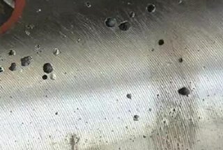
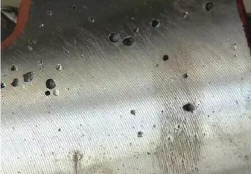
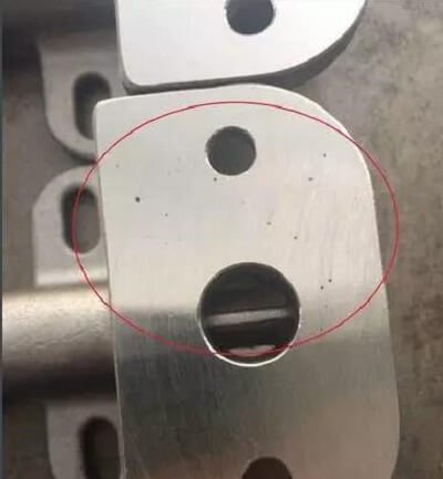
Stomata are holes that exist on the surface or inside it and are round, oval, or irregular in shape.
Sometimes multiple pores form an air pocket, which is generally pear-shaped and located beneath the surface.
Countersinks have an irregular shape and a rough surface.
Air pockets are indented into the surface of the casting, and the surface is relatively smooth.
The appearance of open holes can be easily observed, while subcutaneous air holes can only be detected after machining.
Reasons for Formation:
Prevention Methods:

Features:
Shrinkage cavity is a type of rough surface hole that can be found on the surface or within a casting.
Slight shrinkage refers to many small scattered shrinkages, also known as shrinkage porosity.
The grains around the shrinkage or shrinkage porosity are coarse.
It often appears near the runner in the casting, the base of the riser, thick areas, wall thickness, and large plane thickness.
Reasons for Formation:
Prevention Methods:
Features:
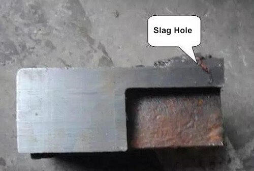
The slag holes are visible or dark holes on castings. They are partially or completely filled with slag and have an irregular shape. It can be difficult to find slag inclusion in small, spot-shaped flux.
After the slag is removed, smooth holes are revealed. These are typically found in the lower part of the pouring position, near the inner runner, or in the dead corners of the casting.
Oxide slag is primarily located near the inner runner on the casting surface in a network-like pattern. It can sometimes appear flaky, wrinkled, or in the form of irregular clouds or flaky interlayers. It may also exist within the casting in the form of floccus.
When broken, the interlayer is often the point of fracture, and the oxide is a source of cracks in the casting.
Reasons for Formation:
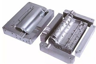
Slag holes are primarily caused by the alloy melting process and the pouring process, including the incorrect design of the pouring system. The mold itself does not cause slag holes, and using metal molds is one effective method for avoiding slag holes.
Prevention Methods:

Features:
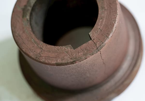
The appearance of cracks can be straight or irregular lines.
The surface of a hot crack has a strong oxidation that results in a dark gray or black color without a metallic shine.
The surface of a cold crack has a clean, metallic luster.
External cracks of castings are typically visible, while internal cracks may require other methods to detect.
Cracks are often linked to defects such as shrinkage and slag inclusion.
They typically occur at sharp corners of the casting, where thick and thin sections meet, and at the hot junction area where the pouring riser is connected to the casting.
Reasons for Formation:
Cracks are common in metal mold casting because the metal mold has no allowance and has a fast cooling rate, which increases the internal stress of the casting.
Factors such as opening the mold too early or late, having a small or large casting angle, having a thin coating layer, and even the mold cavity itself can cause cracking in the casting.
Prevention Methods:
Features:
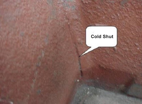
A cold shut is a type of open seam or surface with rounded edges.
The center is divided by oxide scale and is not fully fused.
When the cold shut is severe, it can develop into an “undercast.”
Cold shuts are often found on the top wall of castings, on thin horizontal or vertical planes, at the junction of thick and thin walls, or on thin auxiliary plates.
Reasons for Formations:
Prevention Methods:
Features:
A trachoma is a type of irregular hole that forms on the surface or inside of a casting, and its shape corresponds to the shape of sand grains. When the mold is removed, sand grains that have become embedded in the casting surface are visible, and they can be pulled out. If multiple trachomas exist at the same time, the casting surface takes on an orange peel-like appearance.
Reasons for Formation:
Holes are formed because the sand particles falling on the surface of the sand core are surrounded by the copper liquid and the casting surface.
Prevention Methods:

As the founder of MachineMFG, I have dedicated over a decade of my career to the metalworking industry. My extensive experience has allowed me to become an expert in the fields of sheet metal fabrication, machining, mechanical engineering, and machine tools for metals. I am constantly thinking, reading, and writing about these subjects, constantly striving to stay at the forefront of my field. Let my knowledge and expertise be an asset to your business.