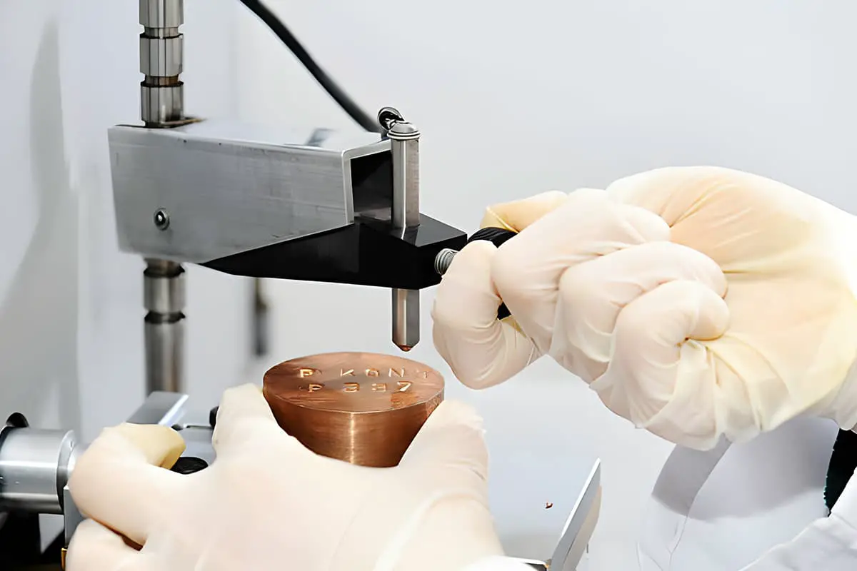
Metal casting is a fundamental process in manufacturing, but have you ever wondered how it stacks up against sand casting? This article dives into the technical and economic advantages and disadvantages of both methods, offering a clear comparison of their performance, costs, and specific applications. Readers will gain a comprehensive understanding of which casting method best suits different manufacturing needs, ensuring informed decisions in production.
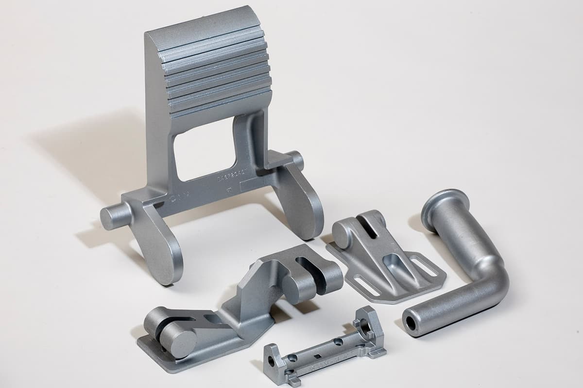
Comparing metal mold casting to sand mold casting, there are numerous technical and economic advantages:
(1) Castings produced by metal molds have superior mechanical properties to those cast in sand molds. For the same alloy, the tensile strength can increase by approximately 25%, yield strength by about 20%, and there are significant improvements in corrosion resistance and hardness.
(2) The precision and surface smoothness of the castings are higher than those made with sand molds, and the quality and dimensions are more stable.

(3) The process yield of the casting is higher, reducing the consumption of liquid metal, generally saving 15-30%.
(4) The use of sand is eliminated or minimized, generally saving 80-100% of mold materials.
Moreover, metal mold casting has a high production efficiency; causes of casting defects are reduced; the process is simple, easy to mechanize and automate.
Despite the advantages of metal mold casting, there are also drawbacks, such as:
(1) The cost of metal mold production is high.
(2) Metal molds are not breathable and have no tolerance, which can lead to casting defects like insufficient pouring, cracking, or white mouth in cast iron parts.
(3) During metal mold casting, factors such as the working temperature of the mold, pouring temperature and speed of the alloy, the time the casting stays in the mold, and the type of coating used, can significantly affect the quality of the casting and require strict control.
Therefore, when deciding to use metal mold casting, it is necessary to consider the following factors comprehensively: the shape and weight of the casting must be appropriate; there must be sufficient batch size; and the production deadline must permit.
There are significant differences between metal and sand molds in terms of their properties. For instance, sand molds are breathable, whereas metal molds are not.
Sand molds have poor thermal conductivity, while metal molds excel in this aspect. Sand molds are retractable, but metal molds are not. These characteristics of metal molds determine their unique principles in the casting formation process.
The influence of changes in the gas state within the mold cavity on casting formation: During metal filling, gases within the mold cavity must be rapidly expelled. However, the non-breathability of metal means that a slight negligence in the process can adversely affect the quality of the casting.
Characteristics of heat exchange during casting solidification: Once the molten metal enters the mold cavity, it transfers heat to the metal mold wall. The liquid metal loses heat through the mold wall, leading to solidification and shrinkage.
Meanwhile, the mold wall expands as it heats up, creating a “gap” between the casting and the mold wall. Until the “casting-gap-mold” system reaches a uniform temperature, the casting can be considered as cooling within the “gap”, while the mold wall is heated through the “gap”.
The impact of metal mold impeding shrinkage on the casting: Metal molds or metal core molds do not retract during the casting solidification process, hindering the casting’s shrinkage – another unique characteristic of them.

Unpreheated metal molds cannot be used for casting due to their high thermal conductivity. If the liquid metal cools too quickly, its flowability drastically decreases, leading to casting defects such as cold shut, insufficient pouring inclusions, and porosity.
Unpreheated metal molds are prone to damage from thermal shock and increased stress during casting. Therefore, metal molds should be preheated prior to use.
The appropriate preheating temperature (i.e., operating temperature) depends on the type of alloy, the structure and size of the casting, and is generally determined through testing. As a rule of thumb, the preheating temperature of a metal mold should not be less than 1500C.
The methods for preheating metal molds include:
(1) Preheating with a blowtorch or gas flame.
(2) Using a resistance heater.
(3) Using an oven for heating, which provides a uniform temperature but is only suitable for small metal molds.
(4) Preheating the metal mold in a furnace, then casting liquid metal to heat the mold. This method is only suitable for small molds as it wastes some liquid metal and can decrease the lifetime of the mold.
The pouring temperature for metal molds is generally higher than for sand casting and can be determined based on the type of alloy, its chemical composition, and the size and thickness of the casting, through testing. The following data can be used as a reference.
Pouring Temperatures for Various Alloys:
Given the rapid cooling and non-porous nature of metal molds, the pouring speed should be slow initially, then fast, and finally slow again. It’s essential to maintain a steady flow of liquid during the pouring process.
The longer a metal core remains within a casting, the stronger the grip on the core due to casting shrinkage, thus requiring greater core withdrawal force.
The optimal duration for a metal core to stay within a casting is when the casting has cooled to a plastic deformation temperature range and has sufficient strength, at which point it’s the best time to withdraw the core.
If the casting stays too long in the metal die, the temperature of the die wall increases, requiring more cooling time and reducing the productivity of the metal die.
The most suitable time for core withdrawal and casting removal is typically determined through experimental methods.
To ensure the quality stability of metal mold castings and normal production, it’s crucial to maintain a constant temperature change in the metal mold during production.
Therefore, after each pour, the metal mold must be opened and left for a certain period until it cools to the specified temperature before the next pour.
If relying on natural cooling, the time required is longer, which reduces productivity, hence forced cooling is commonly used. There are generally several cooling methods:
1. Air cooling: Blowing air around the exterior of the metal mold to enhance convective heat dissipation. While the structure of an air-cooled metal mold is simple, easy to manufacture, and low in cost, the cooling effect isn’t particularly ideal.
2. Indirect water cooling: Installing a water jacket on the back or a specific part of the metal mold. Its cooling effect is better than that of air cooling and is suitable for casting copper parts or forgable cast iron parts. However, intense cooling for casting thin-wall gray iron castings or ductile iron castings might increase casting defects.
3. Direct water cooling: Directly making a water jacket on the back or a specific part of the metal mold, and cooling it with water flowing through the jacket. This method is mainly used for casting steel parts or other alloy castings, where strong cooling of the mold is required. Due to its high cost, it’s only applicable for large-scale production.
If the casting wall thickness varies greatly, when using a metal mold for production, a common method is to heat a part of the metal mold while cooling another part to adjust the temperature distribution of the mold wall.

During the casting process of metal molds, it is common to apply a coating on the working surface of the metal mold.
The coating functions to regulate the cooling speed of the castings, protect the metal mold from erosion and thermal shock caused by high-temperature metal liquid, and facilitate gas release via the coating layer.
Depending on the alloy, the coating might have diverse formulas and is generally composed of three types of substances:
1. Powdery refractory materials (such as zinc oxide, talcum powder, zircon sand powder, diatomaceous earth powder, etc.);
2. Binders (commonly water glass, syrup or waste liquid from paper pulp, etc.);
3. Solvent (water). Specific formulas can be referred to in relevant manuals. The coating should meet the following technical requirements: it should have a certain viscosity for easy spraying, be able to form a uniform thin layer on the surface of the metal mold; after drying, the coating should not crack or peel off and should be easy to remove; it should have a high refractoriness; it should not generate a large amount of gas at high temperatures; it should not react chemically with the alloy (exceptions for special requirements).
Although the coating can reduce the cooling speed of the castings in the metal mold, there is still a certain difficulty in producing ductile iron parts (such as crankshafts) with metal molds that use coatings, because the cooling speed of the castings is still too fast, and the castings are prone to white mouth.
If a sand mold is used, the casting has a slower cooling speed, but shrinkage or porosity easily occurs at the hot junction.
Applying a 4-8mm layer of sand on the surface of the metal mold can result in satisfactory ductile iron castings.
The sand layer effectively regulates the cooling speed of the casting, on one hand preventing the occurrence of a white mouth in the cast iron body, and on the other hand, making the cooling rate faster than sand casting.
Metal molds do not disintegrate, but a thin layer of resin sand can appropriately reduce the shrinkage resistance of the castings. In addition, metal molds have good rigidity, effectively limiting the expansion of spheroidal graphite, achieving riserless casting, eliminating looseness, and improving the compactness of the castings.
If the sand layer of the metal mold is made of resin sand, it can generally be covered by sandblasting. The temperature of the metal mold should be between 180-200℃. Resin sand metal molds can be used to produce ductile iron, gray iron, or steel castings, and their technical effects are significant.
Ways to improve the lifespan of metal molds include:
1. Choosing materials with a high thermal conductivity, low thermal expansion coefficient, and high strength to manufacture metal molds;
2. Appropriate coating technology, strictly following the process specifications;
3. The structure of the metal mold should be reasonable, and residual stresses should be eliminated during the manufacturing process;
4. The grains of the metal mold material should be small.
To ensure the quality of the casting, simplify the structure of the metal mold, and fully exploit its technical and economic benefits, an initial analysis of the casting structure must be performed, and a reasonable casting process must be established.
The quality of the process design of a metal mold casting structure is a prerequisite for ensuring casting quality and exploiting the advantages of metal mold casting. A reasonable casting structure should adhere to the following principles:
(1) The casting structure should not impede demolding or shrinkage;
(2) Thickness variation should not be too large to avoid significant temperature differences, leading to shrinkage cracks and porosity in the casting;
(3) The minimum wall thickness of metal mold castings should be restricted.
Moreover, the precision and smoothness of the non-machined surfaces of the casting should be appropriately required.
The pouring position of the casting directly relates to the number of cores and parting surfaces, the introduction position of liquid metal, the riser’s feeding effect, the degree of exhaust smoothness, and the complexity of the metal mold.
The principles for selecting the pouring position are as follows:
1. Ensure that the metal liquid flows smoothly during filling, allowing for easy venting and preventing entrainment of air and oxidation of the metal;
2. Promote sequential solidification and good shrinkage to ensure the acquisition of dense structure castings;
3. The number of cores should be minimized, and they should be easy to place, stable, and easy to demold;
4. Facilitate the simplification of the metal mold structure and the ease of demolding the casting.
The forms of parting surface are generally vertical, horizontal, and combined (vertical, horizontal mixed parting or curved parting). The principles for selecting the parting surface are as follows:
1. To simplify the metal mold structure and improve the casting accuracy, the shape of the simpler casting should be arranged within the half mold, or most of it should be arranged within the half mold;
2. The number of parting surfaces should be minimized to ensure the aesthetic appearance of the casting and to facilitate demolding and core placement;
3. The selected parting surface should ensure that the setting of the gating and risers is convenient, allowing for smooth metal flow during filling and facilitating the expulsion of gas from the mold cavity;
4. The parting surface should not be selected on the machining reference surface;
5. Avoid curved parting surfaces as much as possible to reduce the number of disassembled parts and moving mold components.
The following factors should be considered when designing the casting system due to the specific characteristics of metal mold casting: the speed of metal casting is high, exceeding that of sand molds by about 20%.
Furthermore, the gas in the mold cavity should be able to be expelled smoothly when the liquid metal fills the mold. Its flow direction should be as consistent as possible with the flow direction of the liquid, effectively pushing the gas towards the riser or the vent riser.
In addition, care should be taken to ensure that the liquid metal flows smoothly during the filling process, without creating any turbulence, impacting the mold wall or cores, or causing any splashing.

The casting system of metal molds generally falls into three categories: top gating, bottom gating, and side gating.
(1) Top gating: This method has a reasonable heat distribution, which is beneficial for sequential solidification and can reduce the consumption of liquid metal. However, the liquid metal flow is unstable, which can cause inclusions. When the casting height is high, it can impact the bottom of the mold or the cores. If used for casting aluminum alloy parts, it is generally only suitable for simple parts with a height less than 100 millimeters.
(2) Bottom gating: The liquid metal flows more smoothly, which is beneficial for venting. However, the temperature distribution is not reasonable, which is not conducive to the smooth solidification of the casting.
(3) Side gating: This method has the advantages of the two aforementioned methods. The liquid metal flows smoothly, which facilitates slag collection and venting. However, the consumption of liquid metal is high, and there is a large workload for gating cleaning.
The structure of the metal mold casting system is basically similar to that of sand mold casting.
However, because the metal mold wall is not breathable and has strong thermal conductivity, the structure of the casting system should facilitate the reduction of the liquid metal flow speed, ensure smooth flow, and reduce its impact on the mold wall.
Besides ensuring that the gas in the mold cavity has ample time to be expelled, it should also ensure that no splashing occurs during the filling process.
When casting ferrous metals with metal molds, due to the high cooling speed of the casting and the rapid increase in the viscosity of the liquid flow, a closed gating system is often used. The ratio of the cross-sectional areas of its various parts is: F_inner : F_transverse : F_vertical = 1 : 1.15 : 1.25
The risers in metal mold casting serve the same functions as those in sand mold casting: they compensate for shrinkage, collect slag, and vent. The design principles for risers in metal molds are the same as those for risers in sand molds.
Because metal molds cool faster and risers often use insulating coatings or sand layers, the size of risers in metal molds can be smaller than those in sand molds.
Editorial Section: Process Parameters of Metal Mold Castings
Due to the characteristics of the metal mold process, the process parameters of its castings are slightly different from those of sand mold castings.
The linear shrinkage rate of metal mold castings is not only related to the linear shrinkage of the alloy, but also to the casting structure, the obstruction of shrinkage in the metal mold, the demolding temperature of the casting, the expansion and size change of the metal mold after heating, etc. Its value also needs to consider leaving room for size modification during the trial casting process.
In order to remove the metal mold core and the casting, an appropriate draft should be taken in the direction of core removal and demolding of the casting. Refer to relevant manuals for the casting draft of various different alloy castings.
The precision of metal mold castings is generally higher than that of sand mold castings, so the machining allowance can be smaller, generally between 0.5 and 4mm.
After determining the casting process parameters, the process drawing of the metal mold casting can be drawn. This drawing is basically the same as the process drawing of sand mold castings.
After the casting process diagram is drawn, the design of the metal mold can proceed. The design primarily involves determining the structure, dimensions, core, exhaust system, and ejection mechanism of the metal mold.
The design of the metal mold should aim for simplicity in structure, convenience in machining, appropriate material selection, and ensure safety and reliability.
The structure of the metal mold depends on the shape and size of the casting, the number of parting surfaces, the type of alloy, and the production volume. Based on the position of the parting surface, there are several forms of metal mold structures:
1. Integral metal mold: This mold has no parting surface and a simple structure, suitable for simple-shaped castings without a parting surface.
2. Horizontal parting metal mold: This mold is suitable for thin-walled wheel castings.
3. Vertical parting metal mold: This type of mold is convenient for establishing gating and exhaust systems, easy to open and close, and suitable for mechanized production. It is often used for producing simple small castings.
4. Composite parting metal mold: It consists of two or more parting surfaces, or even movable blocks, generally used for the production of complex castings. It is convenient to operate and widely used in production.
The main body of a metal mold refers to the part that forms the mold cavity and is used to form the external shape of the casting. The main body structure is related to the size of the casting, its pouring position in the mold, parting surface, and the type of alloy.
The design should strive for accurate dimensions of the mold cavity; facilitate the establishment of gating and exhaust systems, ease of casting ejection, and sufficient strength and rigidity.
Depending on the complexity of the casting and the type of alloy, different materials can be used for the mold core.
Generally, sand cores are used for casting thin-walled complex parts or high-melting-point alloys (such as stainless steel, cast iron), while metal cores are mostly used for casting low-melting-point alloys (such as aluminum, magnesium alloys). Sand cores and metal cores can also be used together in the same casting.
When designing a metal mold, an exhaust system is essential. The following methods can be used for exhaust:
(1) Use the gap between the parting surface or the combination surface of the mold cavity for exhaust.
(2) Create an exhaust groove on the parting surface or the combination surface of the mold cavity, in the core seat or on the surface of the ejector rod.
(3) Install exhaust holes, which are generally located at the highest point of the metal mold.
(4) Exhaust plugs are commonly used in metal molds.
The uneven parts of the metal mold cavity can hinder the shrinkage of the casting, causing resistance when the casting is demolded. An ejector mechanism must be used to eject the casting.
When designing the ejector mechanism, the following points should be noted: prevent damage to the casting, i.e., prevent the casting from being deformed or dented by ejection; prevent the ejector rod from getting stuck.
The clearance between the ejector rod and the ejector hole should be appropriate. If the clearance is too large, metal can easily enter; if it’s too small, it can cause jamming. Experience suggests using D4/dC4 level matching.
When a metal mold is being assembled, accurate positioning of the two halves is required. This is generally achieved in two ways: pin positioning and “stop” positioning. For vertical parting with a circular parting surface, “stop” positioning can be used, while pin positioning is mostly used for rectangular parting surfaces.
The positioning pin should be located within the contour of the parting surface. When the metal mold itself is large and heavy, to ensure convenient positioning during opening and closing of the mold, a guiding format can be adopted.
From the analysis of the causes of metal mold failure, the materials used to manufacture metal molds should meet the following requirements: good heat resistance and thermal conductivity; no deformation or damage when repeatedly heated; certain strength, toughness, and wear resistance; good machinability.
Cast iron is the most commonly used material for metal molds. It has good machinability, is inexpensive, and can be self-made in general factories. In addition, it is heat and wear resistant, making it a suitable metal mold material. Carbon steel and low-alloy steel are only used when high requirements are needed.
The use of aluminum alloys in the manufacture of metal molds has attracted attention abroad. The surface of aluminum molds can undergo anodic oxidation treatment, resulting in an oxide film composed of Al2O3 and Al2O3·H2O.
This film has a high melting point and hardness, and is heat and wear resistant. It is reported that such aluminum metal molds, when using water cooling measures, can not only cast aluminum and copper parts but also be used to cast ferrous metal castings.

