Sheet Metal Bending Calculation: Allowance, Deduction and K-Factor
Have you ever wondered how sheet metal designers ensure the accuracy of their designs? In this blog post, we'll dive into the fascinating world of sheet metal design and explore…
Have you ever wondered how sheet metal is transformed into complex shapes? Bend deduction, a crucial concept in sheet metal fabrication, holds the key. In this blog post, we’ll dive into the intricacies of bend deduction, exploring its formulas, calculators, and practical applications. Join us as we unravel the secrets behind creating precise and beautiful sheet metal components.

Bend deduction is commonly referred to as the “back-off amount”. It is a straightforward algorithm used to explain the process of sheet metal bending.
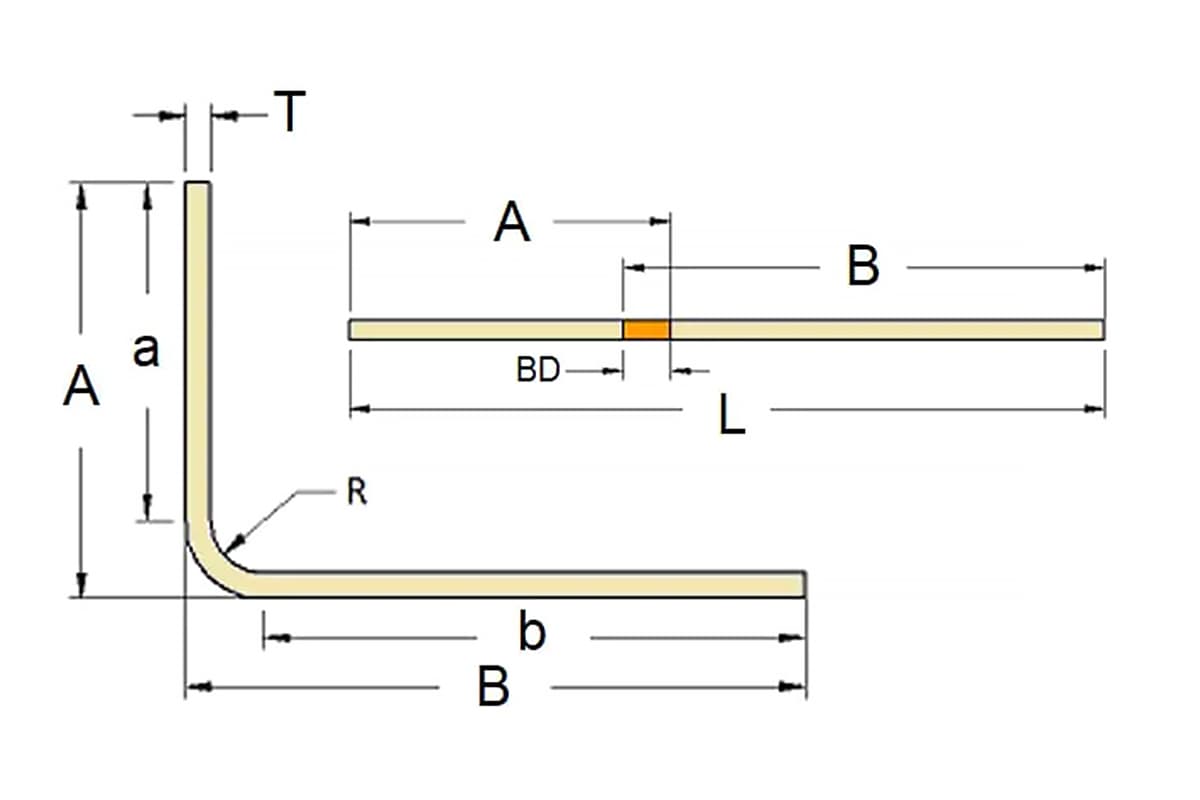
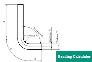
The bend deduction method states that the flattened length (L) of a part is equal to the sum of the lengths of the two flat parts extending to the “cusp” (the point where the two flat parts intersect virtually) minus the bend deduction (BD).
Related calculators:
How to calculate the bending deduction coefficient in sheet metal fabrication?
The bending deduction in sheet metal fabrication is a term used in the setting parameters of Solidworks and is also a formula used for many years in sheet metal fabrication workshops. Let’s take a look at the calculation formula in Solidworks.
Lt = A + B – BD
Where:
The bending deduction in Solidworks is only used for the calculation of 90-degree bends in sheet metal.
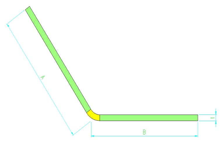
However, it can also be used for the calculation of non-90-degree sheet metal unfolding, but the bending deduction value for non-90-degree bending needs to be used according to the bending coefficient table.
Each manufacturer has a different table, and there may be errors. Some sheet metal factories may not use non-90-degree bending often.
Today, I will mainly share the calculation method of the bending deduction for 90-degree bending that I am familiar with.
Today, I will share the calculation method for the bending deduction of 90-degree bending that I am familiar with.
There are roughly three algorithms for calculating bending deductions:
Sheet metal factories generally use 1.7 times the thickness of the material as the bending deduction, which is the simplest calculation method for sheet metal unfolding.
However, it is not very accurate. If the precision requirement is not high in sheet metal processing, it can be directly used.
Different materials may also have different values; aluminum plates can be calculated based on 1.6 times the thickness of the material, while stainless steel plates can be calculated based on 1.8 times the thickness of the material.
This bending deduction calculation formula has been summarized by the sheet metal manufacturing industry for a long time and is also a rough calculation method.
The theoretical explanation of this calculation formula is: Sheet metal unfolding = Length A + Length B – 2 times the thickness of the material + 1/3 the thickness of the material’s elongation coefficient.
The calculation starts by adding up the lengths of the shortest straight line and the elongation factor. It is believed that the sheet metal will elongate during the bending process.
This formula is derived from a journal article online. Its feature is that it considers the influence of the width of the lower die on the bending deduction.
The test data is derived from experiments on carbon steel plates, and the accuracy of usage for other materials is unknown. I used this formula for the unfolded calculation of a one-time aluminum plate bent with a slot width of 4 times the thickness of the material, and the resulting numerical value was relatively accurate. This formula is very accurate for unfolded calculation of carbon steel plates.
Explanation: t is the actual thickness of the sheet metal, and nominal thickness should not be used for calculation. The above two methods have rough calculations and are not strict in thickness requirements. This formula needs to be calculated based on the actual thickness measured by calipers.
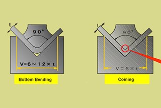
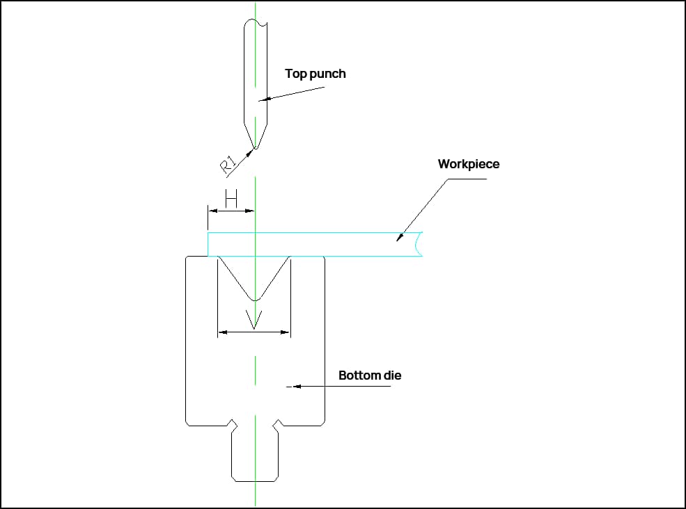
V is the width of the slot in the lower die during bending. Generally, 6-8 times the thickness of the material is taken as the slot width. The actual amount used is calculated according to the actual usage, for example: using 10 lower die bending for 1.5.
There are many methods for calculating bending deductions, including formulas based on the neutral layer theory. This formula is not conducive to actual sheet metal processing, so it is not mentioned here.
The above three methods are the most practical and simplest sheet metal bending deductions or unfolding calculation methods suitable for sheet metal factories.
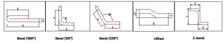
| V | Die width w | Bend Radius | T | 30° | 45° | 60° | 90° | 120° | 150° | 180° | 90°double bend outer layer | Minimum bending size H | Minimum size of Z-bend (Z) |
|---|---|---|---|---|---|---|---|---|---|---|---|---|---|
| 8.0 | 12.0 | R1 | 0.6 | 0.2 | 0.5 | 0.9 | 1.0 | 0.7 | 0.2 | 0.3 | 1.9 | 6.0 | 10.0 |
| 0.8 | 0.3 | 0.6 | 1.0 | 1.6 | 0.8 | 0.3 | 0.4 | 2.2 | |||||
| 1 | 0.3 | 0.7 | 1.1 | 1.7 | 0.9 | 0.3 | 0.5 | 2.5 | |||||
| 1.2 | 0.4 | 0.8 | 1.3 | 2.2 | 1.1 | 0.4 | 0.6 | 2.8 | |||||
| R2 | 0.6 | 0.2 | 0.5 | 0.9 | 1.6 | 0.7 | 0.2 | 0.3 | 1.9 | ||||
| 0.8 | 0.3 | 0.6 | 1.2 | 1.8 | 0.8 | 0.3 | 0.4 | 2.2 | |||||
| 1 | 0.3 | 0.7 | 1.2 | 2.0 | 0.9 | 0.3 | 0.5 | 2.5 | |||||
| 1.2 | 0.4 | 0.8 | 1.4 | 2.3 | 1.1 | 0.4 | 0.6 | 2.8 | |||||
| 10.0 | 14.0 | R1 | 1.5 | 0.7 | 1.2 | 1.6 | 2.5 | 1.3 | 0.5 | 0.7 | 3.2 | 7.0 | 11.0 |
| R2 | 1.5 | 0.6 | 1.0 | 1.5 | 2.7 | 1.3 | 0.5 | 0.7 | 3.5 | ||||
| 12.0 | 16.0 | R1 | 2 | 0.6 | 1.3 | 2.0 | 3.4 | 1.7 | 0.6 | 0.9 | 4.4 | 8.5 | 13.0 |
| R2 | 2 | 0.9 | 1.4 | 2.0 | 3.6 | 1.7 | 0.6 | 0.9 | 4.5 | ||||
| 16.0 | 26.0 | R1 | 2.5 | 0.7 | 1.5 | 2.4 | 4.3 | 2.2 | 0.8 | 1.1 | 5.6 | 12.0 | 20.0 |
| 3 | 0.8 | 1.7 | 2.8 | 5.1 | 2.8 | 0.8 | 1.3 | 5.8 | |||||
| R2 | 2.5 | 0.8 | 1.6 | 2.5 | 4.8 | 2.3 | 0.9 | 1.1 | 6.2 | ||||
| 3 | 1.0 | 2.0 | 3.0 | 5.2 | 2.8 | 1.0 | 1.3 | 6.4 | |||||
| 22.0 | 32.5 | R1 | 4 | 1.0 | 2.4 | 3.5 | 6.5 | 3.3 | 1.1 | 16.0 | 26.0 | ||
| R2 | 4 | 1.2 | 2.6 | 4.0 | 6.8 | 3.5 | 1.1 | ||||||
| 32.0 | 50.0 | R1 | 5 | 1.2 | 3.2 | 4.8 | 8.6 | 4.6 | 1.4 | 24.0 | 38.0 | ||
| 6 | 1.5 | 3.5 | 4.5 | 9.5 | 5.0 | 1.8 | |||||||
| R2 | 5 | 1.5 | 3.4 | 5.0 | 8.8 | 4.5 | 1.6 | ||||||
| 6 | 1.8 | 3.8 | 5.5 | 9.8 | 5.2 | 2.0 |
Explanation:
| Formula | 0.2t | 0.4t | 0.6t | 0.8t | 1.0t | 1.2t | 1.4t | 1.6t |
| Angle | 155-165° | 145-155° | 135-145° | 125-135° | 115-125° | 105-115° | 95-105° | 85-95° |
| Thickness (t) | 15-25° | 25-35° | 35-45° | 45-55° | 55-65° | 65-75° | 75-85° | |
| 0.5 | 0.10 | 0.20 | 0.30 | 0.40 | 0.50 | 0.60 | 0.70 | 0.80 |
| 0.6 | 0.12 | 0.24 | 0.36 | 0.48 | 0.60 | 0.72 | 0.84 | 0.96 |
| 0.8 | 0.16 | 0.32 | 0.48 | 0.64 | 0.80 | 0.96 | 1.12 | 1.28 |
| 1.0 | 0.20 | 0.40 | 0.60 | 0.80 | 1.00 | 1.20 | 1.40 | 1.60 |
| 1.2 | 0.24 | 0.48 | 0.72 | 0.96 | 1.20 | 1.44 | 1.68 | 1.92 |
| 1.5 | 0.30 | 0.60 | 0.90 | 1.20 | 1.50 | 1.80 | 2.10 | 2.40 |
| 2.0 | 0.40 | 0.80 | 1.20 | 1.60 | 2.00 | 2.40 | 2.80 | 3.20 |
| 2.5 | 0.50 | 1.00 | 1.50 | 2.00 | 2.50 | 3.00 | 3.50 | 4.00 |
| 3.0 | 0.60 | 1.20 | 1.80 | 2.40 | 3.00 | 3.60 | 4.20 | 4.80 |
| 4.0 | 0.80 | 1.60 | 2.40 | 3.20 | 4.00 | 4.80 | 5.60 | 6.40 |
| 4.5 | 0.90 | 1.80 | 2.70 | 3.60 | 4.50 | 5.40 | 6.30 | 7.20 |
| 5.0 | 1.00 | 2.00 | 3.00 | 4.00 | 5.00 | 6.00 | 7.00 | 8.00 |
| 6.0 | 1.20 | 2.40 | 3.60 | 4.80 | 6.00 | 7.20 | 8.40 | 9.60 |
| Formula | 0.3t | 0.5t | 0.7t | 0.9t | 1.1t | 1.3t | 1.5t | 1.7t |
| Angle | 155-165° | 145-155° | 135-145° | 125-135° | 115-125° | 105-115° | 95-105° | 85-95° |
| Thickness (t) | 15-25° | 25-35° | 35-45° | 45-55° | 55-65° | 65-75° | 75-85° | |
| 0.5 | 0.15 | 0.25 | 0.35 | 0.45 | 0.55 | 0.65 | 0.75 | 0.85 |
| 0.6 | 0.18 | 0.30 | 0.42 | 0.54 | 0.66 | 0.78 | 0.90 | 1.02 |
| 0.8 | 0.24 | 0.40 | 0.56 | 0.72 | 0.88 | 1.04 | 1.20 | 1.36 |
| 1.0 | 0.30 | 0.50 | 0.70 | 0.90 | 1.10 | 1.30 | 1.50 | 1.70 |
| 1.2 | 0.36 | 0.60 | 0.84 | 1.08 | 1.32 | 1.56 | 1.80 | 2.04 |
| 1.5 | 0.45 | 0.75 | 1.05 | 1.35 | 1.65 | 1.95 | 2.25 | 2.55 |
| 2.0 | 0.60 | 1.00 | 1.40 | 1.80 | 2.20 | 2.60 | 3.00 | 3.40 |
| 2.5 | 0.75 | 1.25 | 1.75 | 2.25 | 2.75 | 3.25 | 3.75 | 4.25 |
| 3.0 | 0.90 | 1.50 | 2.10 | 2.70 | 3.30 | 3.90 | 4.50 | 5.10 |
| 4.0 | 1.20 | 2.00 | 2.80 | 3.60 | 4.40 | 5.20 | 6.00 | 6.80 |
| 4.5 | 1.35 | 2.25 | 3.15 | 4.05 | 4.95 | 5.85 | 6.75 | 7.65 |
| 5.0 | 1.50 | 2.50 | 3.50 | 4.50 | 5.50 | 6.50 | 7.50 | 8.50 |
| 6.0 | 1.80 | 3.00 | 4.20 | 5.40 | 6.60 | 7.80 | 9.00 | 10.20 |
| No. | Angle /Thickness | 0.8 | 1.0 | 1.2 | 1.5 | 2.0 | 2.5 | 3.0 | 4.0 | 5.0 |
| 1 | 0 | 3.00 | 3.60 | 4.00 | 5.00 | 7.00 | 8.40 | 10.00 | 14.00 | 20.00 |
| 2 | 5 | 2.92 | 3.50 | 3.89 | 4.86 | 6.81 | 8.17 | 9.72 | 13.61 | 19.44 |
| 3 | 10 | 2.83 | 3.40 | 3.78 | 4.72 | 6.61 | 7.93 | 9.44 | 13.22 | 18.89 |
| 4 | 15 | 2.75 | 3.30 | 3.67 | 4.58 | 6.42 | 7.70 | 9.17 | 12.83 | 18.33 |
| 5 | 20 | 2.67 | 3.20 | 3.56 | 4.44 | 6.22 | 7.47 | 8.89 | 12.44 | 17.78 |
| 6 | 25 | 2.58 | 3.10 | 3.44 | 4.31 | 6.03 | 7.23 | 8.61 | 12.06 | 17.22 |
| 7 | 30 | 2.50 | 3.00 | 3.33 | 4.17 | 5.83 | 7.00 | 8.33 | 11.67 | 16.67 |
| 8 | 35 | 2.42 | 2.90 | 3.22 | 4.03 | 5.64 | 6.77 | 8.06 | 11.28 | 16.11 |
| 9 | 40 | 2.33 | 2.80 | 3.11 | 3.89 | 5.44 | 6.53 | 7.78 | 10.89 | 15.56 |
| 10 | 45 | 2.25 | 2.70 | 3.00 | 3.75 | 5.25 | 6.30 | 7.50 | 10.50 | 15.00 |
| 11 | 50 | 2.17 | 2.60 | 2.89 | 3.61 | 5.06 | 6.07 | 7.22 | 10.11 | 14.44 |
| 12 | 55 | 2.08 | 2.50 | 2.78 | 3.47 | 4.86 | 5.83 | 6.94 | 9.72 | 13.89 |
| 13 | 60 | 2.00 | 2.40 | 2.67 | 3.33 | 4.67 | 5.60 | 6.67 | 9.33 | 13.33 |
| 14 | 65 | 1.92 | 2.30 | 2.56 | 3.19 | 4.47 | 5.37 | 6.39 | 8.94 | 12.78 |
| 15 | 70 | 1.83 | 2.20 | 2.44 | 3.06 | 4.28 | 5.13 | 6.11 | 8.56 | 12.22 |
| 16 | 75 | 1.75 | 2.10 | 2.33 | 2.92 | 4.08 | 4.90 | 5.83 | 8.17 | 11.67 |
| 17 | 80 | 1.67 | 2.00 | 2.22 | 2.78 | 3.89 | 4.67 | 5.56 | 7.78 | 11.11 |
| 18 | 85 | 1.58 | 1.90 | 2.11 | 2.64 | 3.69 | 4.43 | 5.28 | 7.39 | 10.56 |
| 19 | 90 | 1.50 | 1.80 | 2.00 | 2.50 | 3.50 | 4.20 | 5.00 | 7.00 | 10.00 |
| 20 | 95 | 1.42 | 1.70 | 1.89 | 2.36 | 3.31 | 3.97 | 4.72 | 6.61 | 9.44 |
| 21 | 100 | 1.33 | 1.60 | 1.78 | 2.22 | 3.11 | 3.73 | 4.44 | 6.22 | 8.89 |
| 22 | 105 | 1.25 | 1.50 | 1.67 | 2.08 | 2.92 | 3.50 | 4.17 | 5.83 | 8.33 |
| 23 | 110 | 1.17 | 1.40 | 1.56 | 1.94 | 2.72 | 3.27 | 3.89 | 5.44 | 7.78 |
| 24 | 115 | 1.08 | 1.30 | 1.44 | 1.81 | 2.53 | 3.03 | 3.61 | 5.06 | 7.22 |
| 25 | 120 | 1.00 | 1.20 | 1.33 | 1.67 | 2.33 | 2.80 | 3.33 | 4.67 | 6.67 |
| 26 | 125 | 0.92 | 1.10 | 1.22 | 1.53 | 2.14 | 2.57 | 3.06 | 4.28 | 6.11 |
| 27 | 130 | 0.83 | 1.00 | 1.11 | 1.39 | 1.94 | 2.33 | 2.78 | 3.89 | 5.56 |
| 28 | 135 | 0.75 | 0.90 | 1.00 | 1.25 | 1.75 | 2.10 | 2.50 | 3.50 | 5.00 |
| 29 | 140 | 0.67 | 0.80 | 0.89 | 1.11 | 1.56 | 1.87 | 2.22 | 3.11 | 4.44 |
| 30 | 145 | 0.58 | 0.70 | 0.78 | 0.97 | 1.36 | 1.63 | 1.94 | 2.72 | 3.89 |
| 31 | 150 | 0.50 | 0.60 | 0.67 | 0.83 | 1.17 | 1.40 | 1.67 | 2.33 | 3.33 |
| 32 | 155 | 0.42 | 0.50 | 0.56 | 0.69 | 0.97 | 1.17 | 1.39 | 1.94 | 2.78 |
| 33 | 160 | 0.33 | 0.40 | 0.44 | 0.56 | 0.78 | 0.93 | 1.11 | 1.56 | 2.22 |
| 34 | 165 | 0.25 | 0.30 | 0.33 | 0.42 | 0.58 | 0.70 | 0.83 | 1.17 | 1.67 |
| 35 | 170 | 0.17 | 0.20 | 0.22 | 0.28 | 0.39 | 0.47 | 0.56 | 0.78 | 1.11 |
| 36 | 175 | 0.08 | 0.10 | 0.11 | 0.14 | 0.19 | 0.23 | 0.28 | 0.39 | 0.56 |
| 37 | 180 | 0.00 | 0.00 | 0.00 | 0.00 | 0.00 | 0.00 | 0.00 | 0.00 | 0.00 |
1) The bending deduction table is applicable for sheet metal bending processes where no pressing plate is used and the sheet width is more than three times the thickness (t).
2) When bending on the bending machine, calculations can be made according to this table.
3) According to the dimensions indicated in the diagram, the calculation formula for the unfolded size of the bent workpiece is as follows:
L=a+b-y
Where:
4) Due to the numerous factors influencing sheet metal bending, this sheet metal bending deduction value table is provided for reference only.
The dimensional accuracy of bent workpieces is related to the positional precision of the press brake’s back gauge and the precision of the sheet metal cutting machine. Utilizing reliable machines for both cutting and bending processes can address these issues.
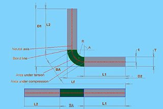
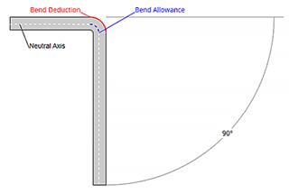
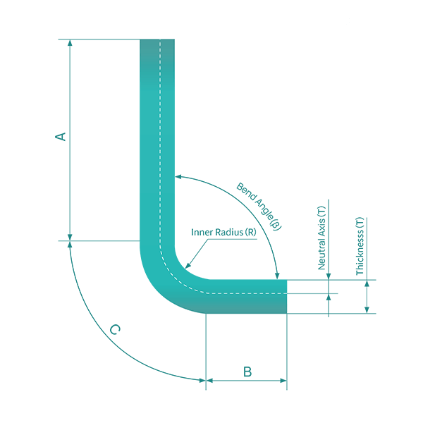
A critical factor affecting the dimensional accuracy of bent workpieces is the accuracy of the sheet metal’s flat pattern development. When a flat sheet is bent into a workpiece with a specific angle, measuring the dimensions of the bent workpiece reveals that they do not equal the dimensions of the flat sheet, as shown in the illustration.
This discrepancy is known as the bending deduction.
If the bending deduction is inaccurate, the flat pattern size will be imprecise, and regardless of the precision of subsequent operations, the final workpiece will not meet the required dimensional accuracy.

The bending deduction is complex, and a rudimentary method is to simply use twice the material thickness.
However, this approach is quite crude. A more refined method is to apply the neutral axis theory from the DIN 6935 standard, which involves calculating a factor ‘k’ and combining it with the thickness and angle of the sheet to be bent.
This formula yields a more precise bending deduction. Yet, even the bending deductions calculated according to the neutral axis theory from DIN 6935 may not be precise enough, as the actual deductions also depend on the characteristics of the material, the thickness, the bending angle, and the tooling used.
Different materials, thicknesses, and calculation methods yield varying bending deductions, as shown in Table below.
Table Deduction value for bending dimensions corresponding to different materials, thicknesses, and methods
| Plate thickness S/mm | Die | Material | -S × 2 | DIN6935 | Database |
| 1.5 | V12/78 | DC04 | -3.00 | -3.00 | -2.90 |
| 1.5 | V08/78 | DC04 | -3.00 | -2.80 | -2.70 |
| 1.5 | V1278 | X5CrNi1810 | -3.00 | -3.00 | -3.10 |
| 4 | V24/78 | S235JRG2 | -8.00 | -7.60 | -7.09 |
| 4 | V30/78 | S235JRG2 | -8.00 | -7.57 | -7.26 |
| 4 | V24/78 | X5CrNi1810 | -8.00 | -8.01 | -7.57 |
| 4 | V30/78 | X5CrNi1810 | -8.00 | -7.90 | -8.01 |
| 6 | V30/78 | S235JRG2 | -12.00 | -11.20 | -10.35 |
| 6 | V4078 | S235JRG2 | -12.00 | -11.60 | -10.62 |
| 6 | V30/78 | X5CrNi1810 | -12.00 | -11.20 | -10.89 |
| 6 | V4078 | X5CrNi1810 | -12.00 | -11.60 | -11.60 |
For example, for a 4mm thick S235JRG2 plate using a V30 lower die, the bending deduction varies by method: twice the material thickness results in 8mm, the DIN 6935 formula yields 7.57mm, and the database empirical value gives 7.26mm.
There are discrepancies between the methods, which become even more significant when workpieces require multiple bends, leading to larger cumulative deviations. The empirical values from the database are derived from extensive practical testing and are stored in the database, providing the utmost precision.

As the founder of MachineMFG, I have dedicated over a decade of my career to the metalworking industry. My extensive experience has allowed me to become an expert in the fields of sheet metal fabrication, machining, mechanical engineering, and machine tools for metals. I am constantly thinking, reading, and writing about these subjects, constantly striving to stay at the forefront of my field. Let my knowledge and expertise be an asset to your business.