Bend Allowance Formula: Calculator & Charts
Have you ever wondered how to precisely calculate the bending allowance for your metal fabrication projects? In this blog post, we'll explore the fascinating world of bend allowance formulas and…
Have you ever wondered how sheet metal parts are designed and manufactured with precision? In this blog post, we’ll dive into the fascinating world of bend allowance – a crucial concept in sheet metal fabrication. As an experienced mechanical engineer, I’ll share my insights and explain how bend allowance enables designers to create accurate flat patterns for bending operations. By the end of this article, you’ll have a solid understanding of bend allowance and its importance in producing high-quality sheet metal components.

Bend allowance is a critical concept in sheet metal fabrication, particularly in the design and manufacturing of press-bent parts. It refers to the additional length of material required to accommodate a bend in the sheet metal. This allowance ensures that the final dimensions of the bent part match the design specifications after bending.
Bend allowance is not merely statistical data; it is derived from empirical measurements and calculations accumulated by experienced mold designers over years of practice. This data is essential for accurately determining the unfolded or flat dimensions of sheet metal parts before bending. By incorporating bend allowance into their calculations, mold designers can predict the final dimensions of a part with high precision.
One of the biggest challenges in sheet metal fabrication is ensuring the accuracy of the unfold dimensions after bending. This involves accounting for various factors such as material type, thickness, bend radius, and bend angle. Accurate bend allowance calculations are essential to avoid discrepancies between the designed and manufactured parts.
Bend allowance is a fundamental tool for mold designers in the sheet metal industry. It allows for precise calculation of the unfold dimensions of press-bent parts, ensuring that the final product meets the design specifications and quality standards. By understanding and applying bend allowance correctly, designers can overcome the challenges associated with bending and achieve high precision in their work.
After learning about bend allowance, the next step is to calculate it. Bend allowance is a critical factor in sheet metal fabrication, as it determines the amount of material needed to accommodate a bend. This ensures that the final dimensions of the part are accurate after bending.
One of the easiest ways to calculate bend allowance is by using a bend allowance calculator. These calculators are designed to quickly and accurately compute the bend allowance based on the input parameters such as material type, thickness, bend angle, and bend radius.
In addition to a dedicated bend allowance calculator, the above calculator can also assist in calculating various parameters related to sheet metal bending, including:
For those interested in a deeper understanding of how to calculate bend allowance manually, we have a detailed analysis available in one of our blog posts. This post covers the step-by-step method to calculate bend allowance, including the formulas and factors involved.
| Material | Thickness | Deduction | Inside R | Angle | Die | Punch | ||
|---|---|---|---|---|---|---|---|---|
| R | V Width | R | Angle | |||||
| Steel Plate | 0.8 | 1.5 | 1.3 | 90° | 0.5 | 8 | 0.2 | 88° |
| 0.9 | 1.7 | 1.3 | 90° | 0.5 | 6 | 0.2 | 88° | |
| 1 | 1.8 | 1.3 | 90° | 0.5 | 8 | 0.2 | 88° | |
| 1.2 | 1.91 | 1 | 90° | 0.4 | 6 | 0.2 | 88° | |
| 1.2 | 2.1 | 1.3 | 90° | 0.5 | 8 | 0.2 | 88° | |
| 1.5 | 2.5 | 1.3 | 90° | 0.5 | 8 | 0.2 | 88° | |
| Cold Rolled Plate | 1.6 | 2.65 | 1.3 | 90° | 0.5 | 8 | 0.6 | 88° |
| 1.8 | 3.4 | 2 | 90° | 0.8 | 12 | 0.6 | 88° | |
| 2 | 3.5 | 2 | 90° | 0.8 | 12 | 0.6 | 88° | |
| 2.3 | 3.75 | 2 | 90° | 0.8 | 12 | 0.6 | 88° | |
| 2.5 | 4.2 | 2.6 | 90° | 0.8 | 16 | 0.6 | 88° | |
| 3 | 5.05 | 2.6 | 90° | 0.8 | 16 | 0.6 | 88° | |
| 4 | 6.9 | 4 | 90° | 0.8 | 25 | 0.6 | 88° | |
| Hot Rolled Plate | 2.3 | 3.77 | 2.6 | 90° | 0.8 | 16 | 0.6 | 88° |
| 3.2 | 5.2 | 2.6 | 90° | 0.8 | 16 | 0.6 | 88° | |
| 4.2 | 7.4 | 4 | 90° | 0.8 | 25 | 0.6 | 88° | |
| 4.8 | 8.1 | 4 | 90° | 0.8 | 25 | 0.6 | 88° | |
| Aluminum Plate | 0.8 | 1.5 | 1.3 | 90° | 0.5 | 6 | 0.2 | 88° |
| 1 | 1.6 | 1.3 | 90° | 0.5 | 8 | 0.2 | 88° | |
| 1.2 | 2.1 | 1.3 | 90° | 0.5 | 8 | 0.2 | 88° | |
| 1.5 | 2.45 | 1.3 | 90° | 0.5 | 8 | 0.2 | 88° | |
| 1.6 | 2.7 | 1.3 | 90° | 0.5 | 8 | 0.6 | 88° | |
| 1.6 | 2.4 | 1.3 | 90° | 0.6 | 10 | 0.6 | 88° | |
| 2 | 3.25 | 2 | 90° | 0.8 | 12 | 0.6 | 88° | |
| 2.3 | 3.6 | 2.6 | 90° | 0.8 | 16 | 0.6 | 88° | |
| 2.5 | 4.2 | 2.6 | 90° | 0.5 | 16 | 0.6 | 88° | |
| 3 | 4.7 | 2.6 | 90° | 0.8 | 16 | 0.6 | 88° | |
| 3.2 | 5 | 2.6 | 90° | 0.8 | 16 | 0.6 | 88° | |
| 3.5 | 5.9 | 4 | 90° | 0.8 | 25 | 1.5 | 88° | |
| 4 | 6.8 | 4 | 90° | 0.8 | 25 | 1.5 | 88° | |
| 5 | 8.1 | 4 | 90° | 0.8 | 25 | 3.2 | 88° | |
| Copper Plate | 0.8 | 1.6 | 1.3 | 90° | 0.5 | 6 | 0.2 | 88° |
| 1 | 1.9 | 1.3 | 90° | 0.5 | 8 | 0.2 | 88° | |
| 1.2 | 2.15 | 1.3 | 90° | 0.5 | 8 | 0.2 | 88° | |
| 1.5 | 2.55 | 1.3 | 90° | 0.5 | 8 | 0.2 | 88° | |
| 2 | 3.5 | 2 | 90° | 0.8 | 12 | 0.6 | 88° | |
| 2.5 | 4.2 | 2.6 | 90° | 0.8 | 16 | 0.6 | 88° | |
| 3 | 5 | 2.6 | 90° | 0.8 | 16 | 0.6 | 88° | |
| 3.2 | 5.1 | 2.6 | 90° | 0.8 | 16 | 0.6 | 88° | |
| 3.5 | 6 | 4 | 90° | 0.8 | 25 | 1.5 | 88° | |
| 4 | 7 | 4 | 90° | 0.8 | 25 | 1.5 | 88° | |
| T | Cold-rolled steel sheet SPCC (electro-galvanized sheet SECC) | ||||||||||||||
| V | Angle | 0.6 | 0.8 | 1 | 1.2 | 1.5 | 2 | 2.5 | 3 | 3.5 | 4 | 4.5 | 5 | Min dimension | Note |
| V4 | 90 | 0.9 | 1.4 | 2.8 | |||||||||||
| 120 | 0.7 | ||||||||||||||
| 150 | 0.2 | ||||||||||||||
| V6 | 90 | 1.5 | 1.7 | 2.15 | 4.5 | ||||||||||
| 120 | 0.7 | 0.86 | 1 | ||||||||||||
| 150 | 0.2 | 0.3 | 0.4 | ||||||||||||
| V7 | 90 | 1.6 | 1.8 | 2.1 | 2.4 | 5 | |||||||||
| 120 | 0.8 | 0.9 | 1 | ||||||||||||
| 150 | 0.3 | 0.3 | 0.3 | ||||||||||||
| V8 | 90 | 1.6 | 1.9 | 2.2 | 2.5 | 5.5 | |||||||||
| 30 | 0.3 | 0.34 | 0.4 | 0.5 | |||||||||||
| 45 | 0.6 | 0.7 | 0.8 | 1 | |||||||||||
| 60 | 1 | 1.1 | 1.3 | 1.5 | |||||||||||
| 120 | 0.8 | 0.9 | 1.1 | 1.3 | |||||||||||
| 150 | 0.3 | 0.3 | 0.2 | 0.5 | |||||||||||
| V10 | 90 | 2.7 | 3.2 | 7 | |||||||||||
| 120 | 1.3 | 1.6 | |||||||||||||
| 150 | 0.5 | 0.5 | |||||||||||||
| V12 | 90 | 2.8 | 3.65 | 4.5 | 8.5 | ||||||||||
| 30 | 0.5 | 0.6 | 0.7 | ||||||||||||
| 45 | 1,0 | 1.3 | 1.5 | ||||||||||||
| 60 | 1.7 | 2 | 2.4 | ||||||||||||
| 120 | 1.4 | 1.7 | 2 | ||||||||||||
| 150 | 0.5 | 0.6 | 0.7 | ||||||||||||
| V14 | 90 | 4.3 | 10 | ||||||||||||
| 120 | 2.1 | ||||||||||||||
| 150 | 0.7 | ||||||||||||||
| V16 | 90 | 4.5 | 5 | 11 | |||||||||||
| 120 | 2.2 | ||||||||||||||
| 150 | 0.8 | ||||||||||||||
| V18 | 90 | 4.6 | 13 | ||||||||||||
| 120 | 2.3 | ||||||||||||||
| 150 | 0.8 | ||||||||||||||
| V20 | 90 | 4.8 | 5.1 | 6.6 | 14 | ||||||||||
| 120 | 2.3 | 3.3 | |||||||||||||
| 150 | 0.8 | 1.1 | |||||||||||||
| V25 | 90 | 5.7 | 6.4 | 7 | 17.5 | ||||||||||
| 120 | 2.8 | 3.1 | 3.4 | ||||||||||||
| 150 | 1 | 1 | 1.2 | ||||||||||||
| V32 | 90 | 7.5 | 8.2 | 22 | |||||||||||
| 120 | 4 | ||||||||||||||
| 150 | 1.4 | ||||||||||||||
| V40 | 90 | 8.7 | 9.4 | 28 | |||||||||||
| 120 | 4.3 | 4.6 | |||||||||||||
| 150 | 1.5 | 1.6 | |||||||||||||
| T | Aluminum sheet L2Y2 material | ||||||||||||||
| V | Angle | 0.6 | 0.8 | 1 | 1.2 | 1.5 | 2 | 2.5 | 3 | 3.5 | 4 | 4.5 | 5 | Min dimension | Note |
| V4 | 1.4 | 2.8 | |||||||||||||
| V6 | 1.6 | 4.5 | |||||||||||||
| V7 | 1.6 | 1.8 | 5 | ||||||||||||
| V8 | 1.8 | 2.4 | 3.1 | 5.5 | |||||||||||
| V10 | 2.4 | 3.2 | 7 | ||||||||||||
| V12 | 2.4 | 3.2 | 8.5 | ||||||||||||
| V14 | 3.2 | 10 | |||||||||||||
| V16 | 3.2 | 4 | 4.8 | 11 | |||||||||||
| V18 | 4.8 | 13 | |||||||||||||
| V20 | 4.8 | 14 | |||||||||||||
| V25 | 4.8 | 5.4 | 6 | 17.5 | |||||||||||
| V32 | 6.3 | 6.9 | 22 | ||||||||||||
| T | Copper sheet | ||||||||||||||
| V | Angle | 0.6 | 0.8 | 1 | 1.2 | 1.5 | 2 | 2.5 | 3 | 3.5 | 4 | 4.5 | 5 | Min dimension | Note |
| 90 | 3.6 | 5.2 | 6.8 | 8.4 | 28 | ||||||||||
| 120 | |||||||||||||||
| 150 | |||||||||||||||
Note: (For C-shaped profiles with a thickness of 2.0, the V12 coefficient is 3.65, while other 2.0 sheet materials have a coefficient of 3.5.) The bending allowance coefficient for 2.0 sheet with hemming is 1.4.
| MATERLAL | SPCC | SUS | LY12 | SECC | ||||
| T | ΔT | ΔK | ΔT | ΔK | ΔT | ΔK | ΔT | ΔK |
| T=0.6 | 1.25 | 1.26 | ||||||
| T=0.8 | 0.18 | 1.42 | 0.15 | 1.45 | 0.09 | 1.51 | ||
| T=1.0 | 0.25 | 1.75 | 0.2 | 1.8 | 0.3 | 1.7 | 0.38 | 1.62 |
| T=1.2 | 0.45 | 1.95 | 0.25 | 2.15 | 0.5 | 1.9 | 0.43 | 1.97 |
| T=1.4 | 0.64 | 2.16 | ||||||
| T=1.5 | 0.64 | 2.36 | 0.5 | 2.5 | 0.7 | 2.3 | ||
| T=1.6 | 0.69 | 2.51 | ||||||
| T=1.8 | 0.65 | 3 | ||||||
| T=1.9 | 0.6 | 3.2 | ||||||
| T=2.0 | 0.65 | 3.35 | 0.5 | 3.5 | 0.97 | 3.03 | 0.81 | 3.19 |
| T=2.5 | 0.8 | 4.2 | 0.85 | 4.15 | 1.38 | 3.62 | ||
| T=3.0 | 1 | 5 | 5.2 | 1.4 | 4.6 | |||
| T=3.2 | 1.29 | 5.11 | ||||||
| T=4.0 | 1.2 | 6.8 | 1 | 7 | ||||
| T=5.0 | 2.2 | 7.8 | 2.2 | 7.8 | ||||
| T=6.0 | 2.2 | 9.8 | ||||||
| Aluminum sheet thickness | Bending angle | Bend allowance |
| AL-0.8 | 90 | 1.5 |
| AL-1.0 | 90 | 1.5 |
| 45, 135 | 0.5 | |
| AL-1.2 | 90 | 2.0 |
| 45, 135 | 0.5 | |
| AL-1.5 | 90 | 2.5 |
| 45, 135 | 0.5 | |
| 60, 120 | 1.5 | |
| AL-2.0 | 90 | 3.0 |
| 45, 135 | 1.0 | |
| 60, 120 | 2.5 | |
| 90-degree groove | 1.5 | |
| AL-2.5 | 90 | 4.0 |
| 45, 135 | 1.5 | |
| 60, 120 | 3.0 | |
| 90-degree groove | 2.0 | |
| AL-3.0 | 90 | 5.0 |
| 45, 135 | 3.0 | |
| 60, 120 | 4.5 | |
| 90-degree groove | 2.5 |
1) The bending allowance table is applicable for sheet metal bending processes where no pressure plate is used, and the width of the plate is greater than three times the thickness.
2) When bending on a press brake machine, calculations can be made according to this table.
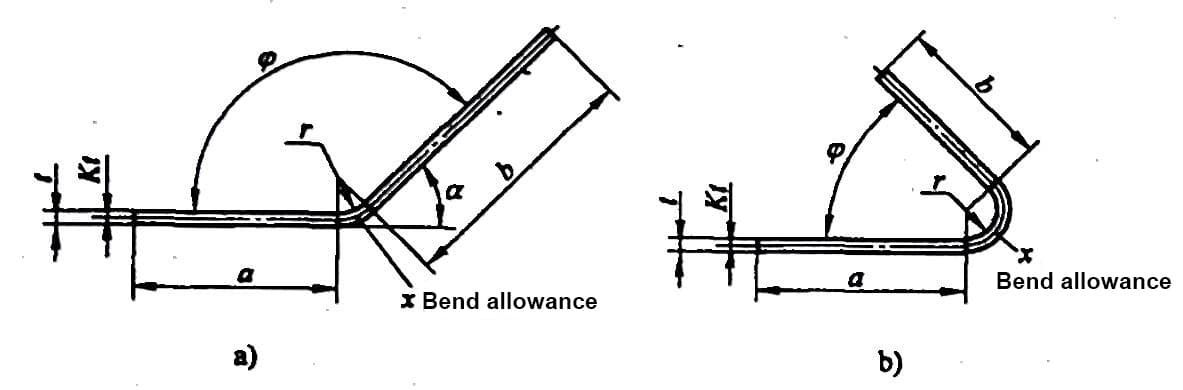
3) As per the dimensions marked in the diagram, the calculation formula for the unfolded dimensions of the bent workpiece is as follows:
L = a + b + x
In this equation,
4) Due to the numerous factors affecting sheet metal bending, this bending allowance table for sheet metal bending should be used as a reference only.
Bend forming 0°L=A+B-0.43T, T=Thickness, Deduction=0.43T
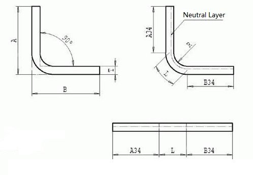
Formula: L(unfold length)=A(Outside size)+B(Outside size)-K(K-factor)
None-90° bend unfold according to the neutral layer, the distance from neutral to sheet inner side is T/3, inner R can refer to the above chart.
V-die width is 6-8 times the plate thickness
None-90°bend = 180°- Angle/90°*Deduction
The deduction is 1.8 times the steel plate thickness and 1.6 times the aluminum plate.
For plate under 2mm, K-factor is 0.432, R=plate thickness, unfold size can accurate to 0.05.
Generally, when design the sheet metal parts, the min inner R=thickness/2, if less than that, the grooving (V-cutting) will be required to solve the problem.
Further reading:

As the founder of MachineMFG, I have dedicated over a decade of my career to the metalworking industry. My extensive experience has allowed me to become an expert in the fields of sheet metal fabrication, machining, mechanical engineering, and machine tools for metals. I am constantly thinking, reading, and writing about these subjects, constantly striving to stay at the forefront of my field. Let my knowledge and expertise be an asset to your business.