0° – 180° Bend Allowance Chart for Sheet Metal Bending
Have you ever wondered how sheet metal parts are designed and manufactured with precision? In this blog post, we'll dive into the fascinating world of bend allowance - a crucial…
Have you ever wondered how sheet metal designers ensure the accuracy of their designs? In this blog post, we’ll dive into the fascinating world of sheet metal design and explore two essential concepts: bend allowance and bend deduction. We’ll also introduce the K factor and its role in calculations. Join us as we unravel these topics and provide valuable insights from industry experts.
In the field of sheet metal design, terms like bend allowance, bend deduction, and K factor are often heard. But what exactly do these terms mean? And how can we calculate them?
In this post, we will provide detailed answers to these questions.

Engineers and sellers involved in the design and production of sheet metal parts use various algorithms to calculate the actual length of the material in its unfolded state to ensure the desired dimensions of the part after final bending and forming.
The most commonly used method is the simple “finger pinching rule”, an algorithm based on personal experience, which takes into account factors such as the type and thickness of the material, the radius and angle of bending, the type of machine, and the bending speed.
With the rise of computer technology, computer-aided design (CAD) is increasingly used to take advantage of the computer’s superior analytical and computational abilities.
However, even when a computer program simulates bending or unfolding of sheet metal, it still needs a method for accurate calculation.
Most commercial CAD and 3D solid modeling systems provide a general and powerful solution for this, and are usually compatible with the original finger-pinching rule method and offer customization options to input specific content into their calculation process.
SolidWorks is a leader in providing this capability for sheet metal design.
In conclusion, two popular sheet metal bending algorithms are widely adopted today: one based on bending allowance, and the other based on bending deduction.
To enhance the readers’ understanding of basic concepts in sheet metal design calculation, the following points will be summarized and explained:
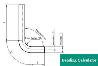
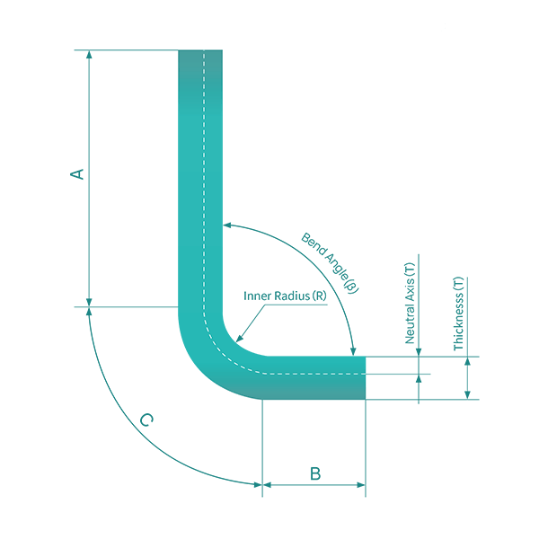
For a clearer understanding of bend allowance, refer to Figure 1, which illustrates a single bend in a sheet metal component. Figure 2 displays the part in its unfolded state.
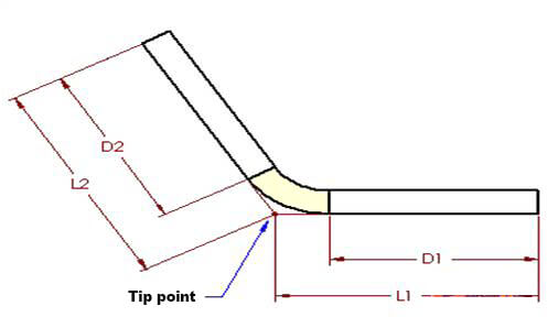
Figure 1

Figure 2
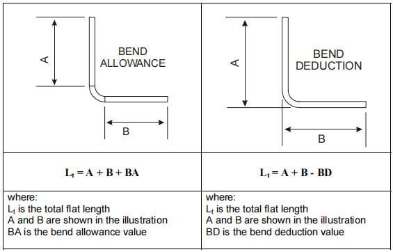
The bending allowance algorithm describes the unfolded length (LT) of a sheet metal part as the sum of the lengths of each segment after the part is flattened, plus the length of the flattened bend area.
The bend allowance (BA) represents the length of the flattened bend area. Thus, the total length of the part can be expressed as equation (1):
LT = D1 + D2 + BA (1)
The bending area (illustrated as light yellow in the illustration) is the area that theoretically undergoes deformation during the bending process.
To determine the geometry of the unfolded part, follow these steps:
The task of determining the length of the flattened bending area, represented by BA in the figure, is a bit more challenging.
The value of BA varies based on factors such as material type, material thickness, bending radius and angle, as well as the bending process, machine type, and machine speed.
The value of BA can be obtained from various sources, including sheet metal material suppliers, experimental data, experience, and engineering manuals.
In SolidWorks, one can directly input BA values or use the K factor (which will be discussed later) to calculate the values.
The bending table method is the most accurate way to specify different bending allowances for different situations with different thicknesses, radii, and angles.
Creating the initial bending table may take some time, but once it’s formed, parts of it can be reused in the future.
The same or different information can be entered for each bend in the part.
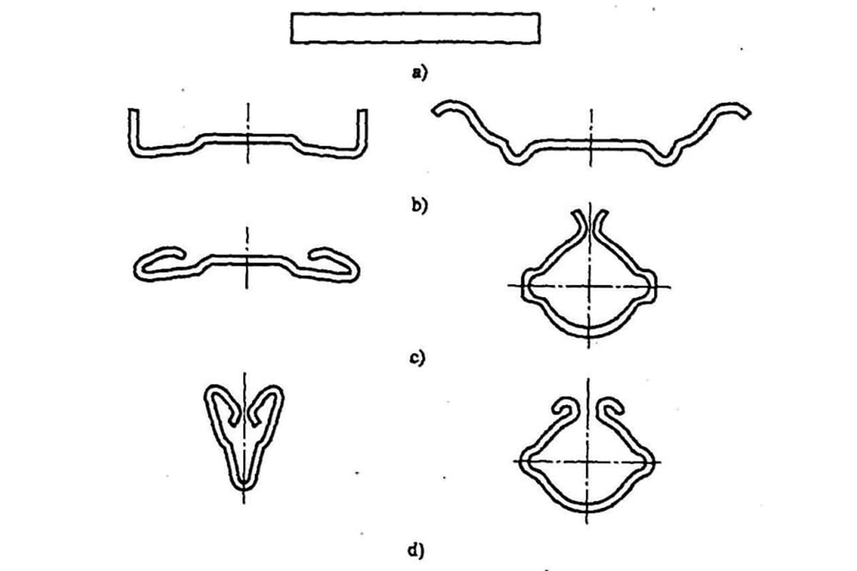
1) Standards for Common Bending
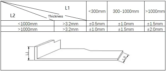
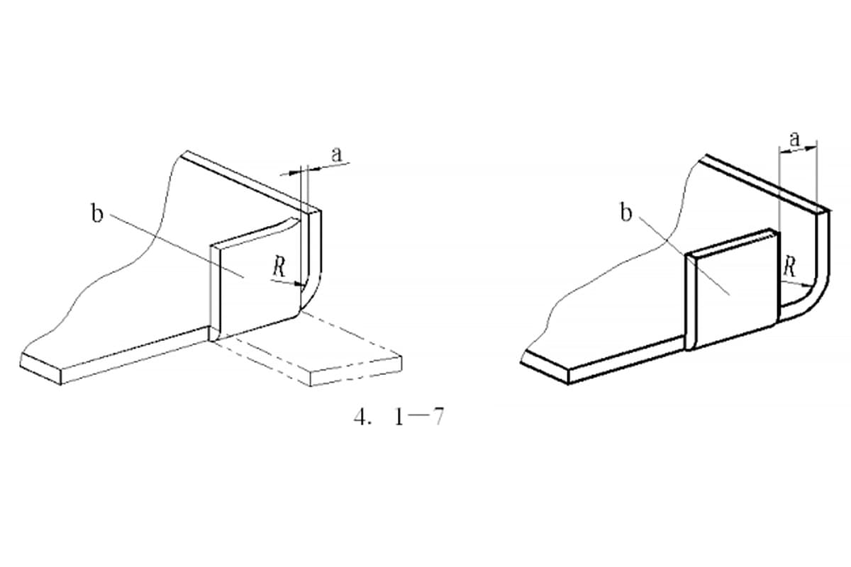
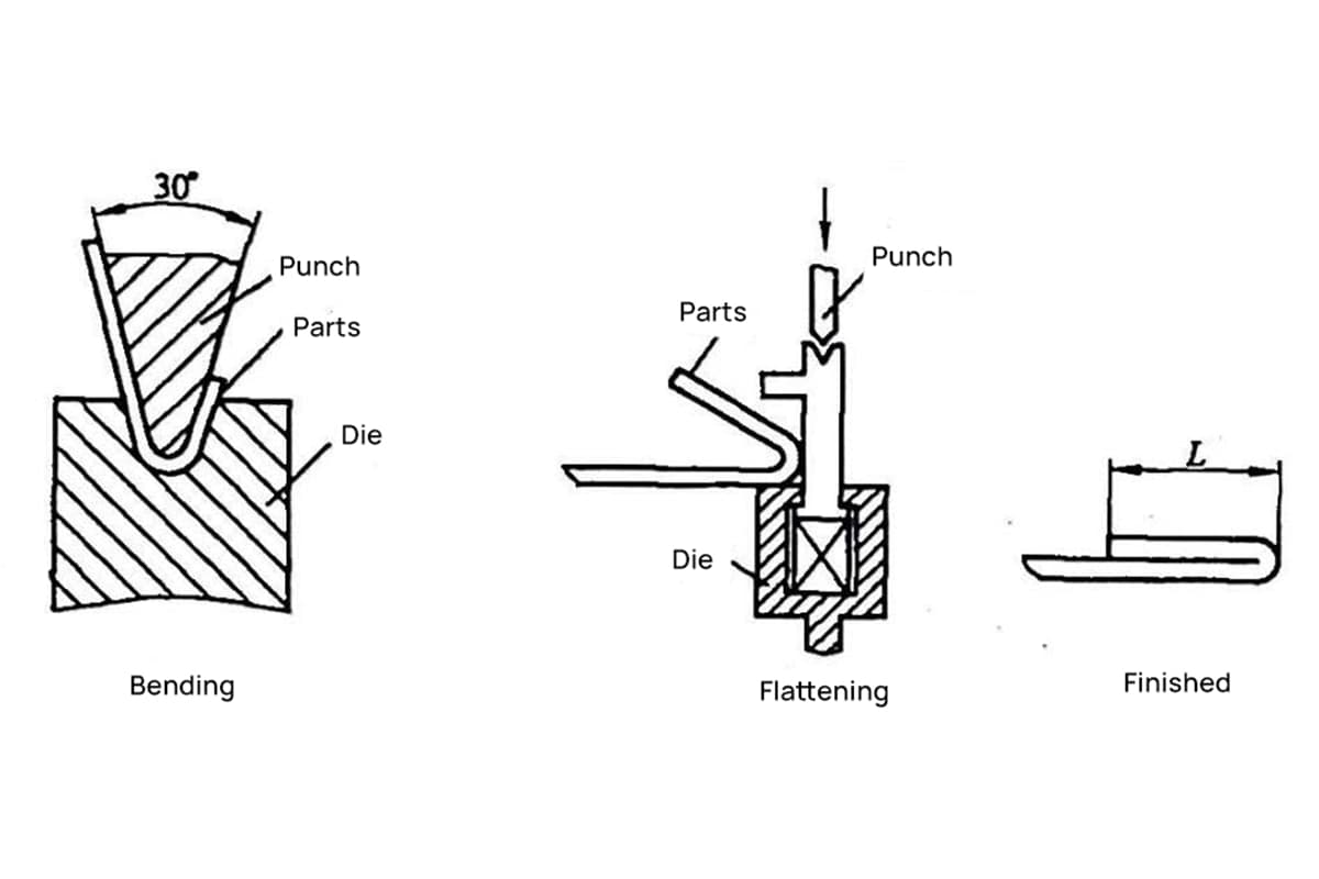
2) Standards for Z Bending
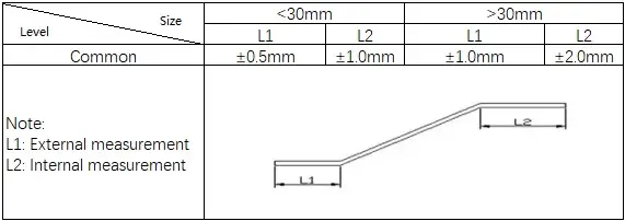
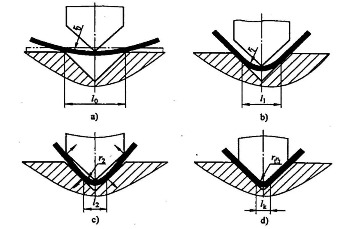
3) Standards for V Bending

4) Standards for U Bending

Related reading: V & U-shaped Bend Force Calculator
Bending Deduction is a term used to describe the amount of setback in the process of sheet metal bending. This is another simple algorithm for describing the process.
Figures 1 and 2 also apply to this concept. According to the bending deduction method, the flattened length (LT) of the part is equal to the sum of the lengths of the two flat sections extending to the “tip point” (the hypothetical intersection of the two flat sections), minus the bending deduction (BD).
Thus, the total length of the part can be expressed as shown in equation (2):
LT = L1 + L2 – BD (2)
The value of BD can be determined or obtained from various sources such as sheet metal material suppliers, experimental data, experience, engineering manuals with equations or tables, etc.

Figure 3
It’s important for users familiar with the Bending Deduction method to understand the relationship with the Bending Allowance method, which is commonly adopted in SolidWorks.
The relationship between the two values can easily be deduced by using the two geometries of bending and unfolding of parts.
By comparing equations (1) and (2), we have:
LT = D1 + D2 + BA (1) LT = L1 + L2 – BD (2)
And therefore,
D1 + D2 + BA = L1 + L2 – BD (3)
In Figure 3, angle A represents the bending angle, which describes the angle swept by the part during bending, and also the angle of the arc formed by the bending area, which is shown in two halves.
By using the dimensions and principles of right triangles, we can derive the following equations:
D1 = L1 – (R + T)TAN(A/2) (4) D2 = L2 – (R + T)TAN(A/2) (5)
By substituting equations (4) and (5) into equation (3), we can obtain the relationship between BA and BD:
BA = 2(R + T)TAN(A/2) – BD (6)
And when the bending angle is 90 degrees, this equation simplifies to:
BA = 2(R + T) – BD (7)
These equations (6) and (7) provide a convenient method for converting from one algorithm to the other, using only the material thickness, bending angle/radius, etc. as parameters.
For SolidWorks users, these equations provide a direct method for converting Bend Deduction to Bend Allowance.
The Bend Allowance value can be used for the entire part or each individual bend, or it can be included in a bending data table.
The K-factor is a standalone value that explains the bending and unfolding of sheet metal in various geometric scenarios.
It is also an autonomous value that is used to calculate the Bending Allowance (BA) under various conditions such as different material thicknesses, bending angles, and radii.
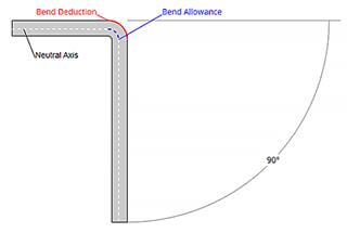
Figures 4 and 5 are provided to help clarify the in-depth definition of the K-factor.

Figure 4

Figure 5
We can confirm that there is a neutral axis in the thickness of the sheet metal part. The sheet metal material in this neutral axis in the bending region is neither stretched nor compressed, meaning it is the only area that doesn’t deform during bending.
Figures 4 and 5 show the boundary between the pink and blue regions.
During bending, the pink region compresses and the blue region extends. If the neutral sheet metal layer remains undeformed, the length of its arc in the bending region remains the same whether the part is bent or flattened.
As a result, the bending allowance (BA) should equal the length of the neutral layer’s arc in the bending region of the sheet metal part, which is shown in green in Figure 4.
The position of the neutral layer of sheet metal is dependent on the properties of a specific material, such as ductility.
It’s assumed that the distance between the neutral sheet metal layer and the surface is “t”, or the depth from the surface of the sheet metal part into the material in the thickness direction.
As a result, the radius of the neutral layer’s arc can be expressed as (R + t). Using this expression and the bending angle, the length of the neutral layer’s arc (BA) can be calculated.
BA = Pi(R+T)A/180
In order to simplify the definition of the sheet metal neutral layer and make it applicable to all materials, the concept of the K-factor was introduced.
The definition of the K-factor is: it is the ratio of the thickness of the sheet metal’s neutral layer to the overall thickness of the sheet metal part material. In other words, the K-factor is defined as:
K = t/T
Therefore, the value of K will always be within the range of 0 to 1. If a K-factor is 0.25, it indicates that the neutral layer is situated at 25% of the total thickness of the sheet metal material.
Likewise, if it is 0.5, it signifies that the neutral layer is located at 50% of the entire thickness, and so forth.
By combining the equations mentioned above, the following equation (8) can be obtained:
BA = Pi(R+K*T)A/180 (8)
Therefore, the value of K will always be between 0 and 1.
If a K-factor is 0.25, it means that the neutral layer is located at 25% of the thickness of the part sheet metal material.
Similarly, if it is 0.5, it means that the neutral layer is located at 50% of the whole thickness, and so on.
The origin of the K-factor can be traced back to traditional sources such as sheet metal material suppliers, test data, experience, manuals, etc.
However, in some cases, the value provided may not be expressed as a clear K-factor, but it is still possible to find the relationship between them.
For instance, if a manual or literature describes the neutral axis as “positioned at 0.445x material thickness from the sheet metal surface”, it can be interpreted as a K-factor of 0.445, meaning k = 0.445.
When this value of K is substituted into equation (8), the following formula can be obtained.
BA = A (0.01745R + 0.00778T)
If equation (8) is modified by another method, the constant in equation (8) is calculated, and all variables are retained, the following can be obtained:
BA = A (0.01745 R + 0.01745 K*T)
By comparing the two equations, it is easy to determine that 0.01745 * k = 0.00778, and therefore, k can be calculated to be 0.445.
It has been discovered that the SolidWorks system also provides a bending allowance algorithm for specific materials when the bending angle is 90 degrees. The calculation formula for each material is as follows:
In fact, by simplifying equation (7) and setting the bending angle to 90 degrees, the constant can be calculated and the equation can be transformed as follows:
BA = (1.57 * K * T) + (1.57 *R)
Therefore, by comparing the above calculation formula, the value of K for soft brass or soft copper materials can be obtained as 1.57xk = 0.55, or K = 0.35.
Using the same method, it is easy to calculate the K-factor values for the several types of materials listed above.
As discussed previously, there are several sources from which the K-factor value can be obtained, such as material suppliers, test data, experience, and manuals.
To establish an accurate sheet metal model using the K-factor method, it’s crucial to find the appropriate source of K-factor that meets your engineering requirements. This will ensure that the physical part results are as accurate as desired.
In some situations, it may not be possible to obtain accurate results by using a single K-factor value alone, especially when it is necessary to accommodate a wide range of bending scenarios.
In such cases, it’s advisable to use the bending allowance (BA) value directly for a single bend of the entire part, or to use a bend table to describe the different BA, bending deduction (BD), or K-factor values corresponding to different A, R, and T values across the entire range.
Additionally, equations can be used to generate data like the sample bend table provided by SolidWorks. If necessary, cells in the bend table can also be modified based on experimental or empirical data.
The installation directory of SolidWorks includes bend allowance tables, bend deduction tables, and K-factor tables, which can be edited and customized as needed.
This post provides a comprehensive overview of the common calculation methods and their underlying principles used in the design and fabrication of sheet metal parts.
It covers the calculation of bending allowances, bending deductions, and K-factors, and explains the differences between these methods and their inter-relationships.
It serves as a useful reference for engineers and technical professionals in the industry.
Note:

As the founder of MachineMFG, I have dedicated over a decade of my career to the metalworking industry. My extensive experience has allowed me to become an expert in the fields of sheet metal fabrication, machining, mechanical engineering, and machine tools for metals. I am constantly thinking, reading, and writing about these subjects, constantly striving to stay at the forefront of my field. Let my knowledge and expertise be an asset to your business.