Aluminum Plate Bending: Which Types Can You Use?
Ever wondered why some aluminum plates bend effortlessly while others crack? The key lies in the type and state of the aluminum. This article explores various aluminum grades, like 3003…
Have you ever wondered why bending high-strength steel plates can be so tricky? This article explores the common defects encountered during the free bending process of high-strength steel plates, such as cracking and springback. It delves into the causes of these issues and offers practical solutions to improve bending precision and efficiency. By understanding the key factors influencing these defects, you can enhance your bending techniques and minimize production costs. Dive in to learn how to tackle these challenges effectively and ensure high-quality bent parts.
With the advancements in vehicle lightweighting and collision safety, the use of high-strength steel plates in the automotive industry is gradually increasing.
Currently, high-strength plate bending parts are mainly utilized in structural components of automobile chassis.
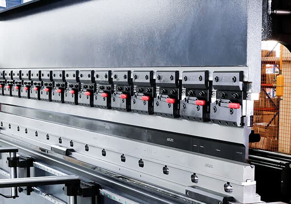
Sheet metal bending can be done in two ways:
(1) Stamping Bending
This bending technique demands that the bending die and sheet material be fully adhered to each other and match the sheet metal parts precisely.
Due to the high cost of mold development, it is suitable for sheet metal parts with intricate structures.
This method eliminates the need for the bending die to correspond with each sheet metal part individually.
By adjusting the bending process and the press brake machine’s stroke, a flexible bending mold can be produced to accommodate the requirements of various bending parts.
It’s cost-effective for sheet metal parts with simple structures, as the development cost of a press brake mold is low.
However, when high-strength plates are bent using the free bending method on a press brake, production efficiency is reduced due to various defects caused by factors such as material performance, equipment conditions, and bending process parameters.
This can result in economic losses.
In this article, we will analyze the main defect types in free bending of high-strength steel plates and propose corresponding improvement measures and countermeasures.
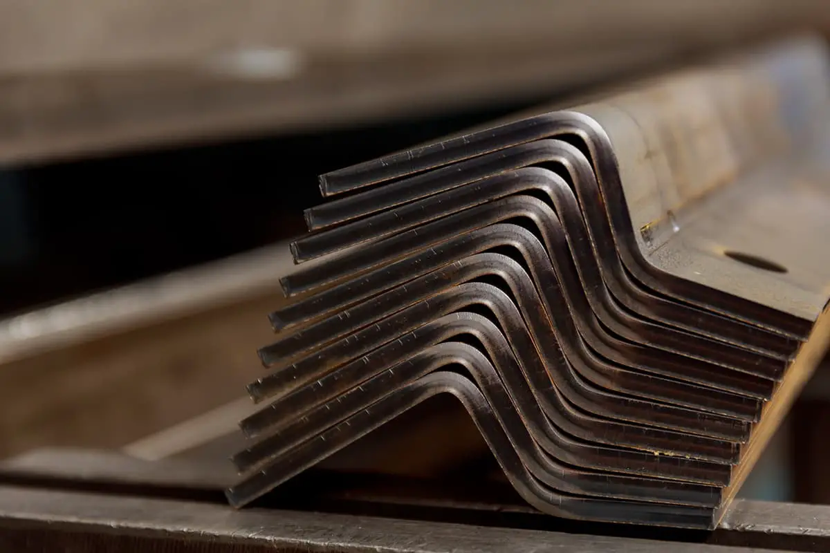
When the inner bending radius (R) is reduced to a certain extent, excessive deformation can result in cracking or microcracking of the lateral longitudinal material outside the sheet material at the bending radius, as illustrated in Figure 1.
During the initial phase of trial production of high-strength steel bending parts, flexural cracking defects are a common occurrence, leading to not only wastage of the plate but also hindrance to the normal progress of the project.
The main factors contributing to cracking in high-strength steel bending parts can be attributed to the following aspects.
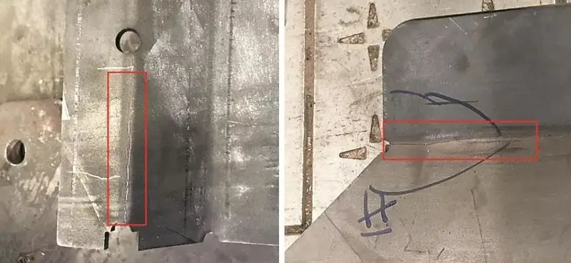
Fig 1 Cracking at bend radius of high strength steel bending parts
The minimum bending radius, which prevents cracking of the outer fiber, is the ultimate bending radius.
The minimum bending radius is dependent on several factors including the mechanical properties of the material, fiber direction of the plate, surface quality of the plate, edge quality, and plate thickness.
As the strength of the material increases, its plasticity decreases, resulting in a larger minimum bending radius.
Additionally, cold-rolled plates tend to exhibit anisotropy, with greater plasticity along the direction of the fiber than perpendicular to it.
Therefore, when the bending line is perpendicular to the fiber direction of the sheet, the minimum bending radius is smaller.
To prevent bending cracks or microcracks, it’s essential to accurately predict the minimum bending radius of the sheet material in advance.
For instance, the bending radius of protective steel BP500 (with a yield strength of not less than 1250MPa) should be at least 4 times the material thickness and the bending line must be perpendicular to the fiber direction of the sheet material.
To avoid bending cracking caused by an insufficient bending radius, it’s crucial to consider the relationship between the bending radius and the minimum bending radius as well as the relationship between the bending line and the fiber direction of the sheet material during the digital-analog review stage.
In the bending process, it’s important to correctly position the bending line to ensure the accuracy of the bent parts.
Traditionally, manual line positioning methods include manual or laser marking positioning, process notch positioning, and machine tool block positioning.
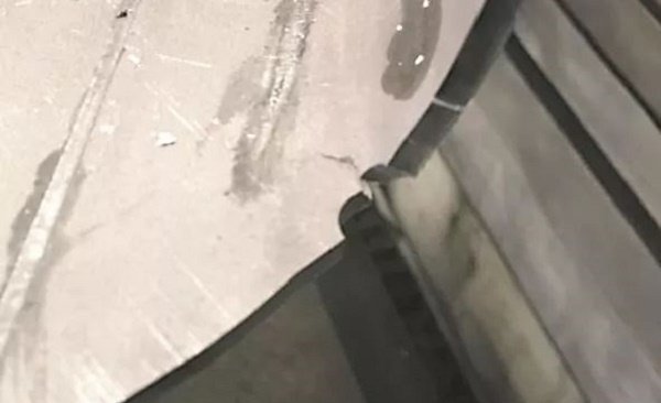
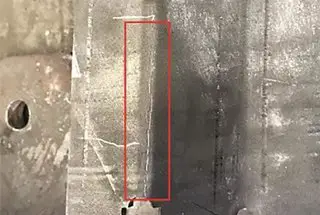
FIG. 2 Crack at process gap of high-strength plate bending parts
During the bending test of BP500 sheet materials, when the process notch positioning method is used, cracks can occur at the positioning gap, as shown in Figure 2.
The notching treatment changes the original smooth edge shape of the material into a sharp one, causing stress to concentrate at the gaps. When the sheet material is bent, the stress value at the gap exceeds the strength limit and cracking occurs.
This highlights the high surface and edge quality requirements of BP500 plates during the bending process. The surface should be free of cracks, scratches, burrs, and notches on the edge.
Therefore, the BP500 plate cannot be positioned for bending using the process notch positioning method.
It’s recommended to use the sheet metal non-damaged machine tool block positioning method for bending.
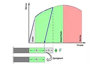
Bending spring back refers to the situation when the bending angle and radius of the bent parts are different from the intended values after being removed from the press brake tooling.
The resilience of the bending parts is mainly influenced by the following factors:
The size of the springback angle is proportional to the yield strength and hardening index of the material, and inversely proportional to the elastic modulus.
The yield strength of BP500 protective steel is no less than 1250 MPa, so its springback trend is larger than that of ordinary steel plates.
Main methods to improve the precision of bending parts:
The improvement of BP500 plate bending springback was mainly achieved through the mold compensation method, as the reinforcement plate could not be added to the bending position due to limitations in the shape of the bending parts.
Table 1 shows the results of experiments conducted on bending BP500 plates with a bending radius of 20mm and bending center angles of 90°, 120°, and 135°, respectively.
Table 1 The relationship between bending springback angle and bending center angle for BP500 plate
| Bending Center Angle | Springback Angle |
|---|---|
| 90° | 14° |
| 120° | 18° |
| 135° | 21° |
As shown in the table, it can be observed that as the bending center angle increases, the resilience also increases.
In the process of designing the bending die for BP500 material, a compensation of 14° for the springback angle (for a 90° bend angle) was made to the press brake tooling.
The mold was designed with a negative angle to optimize the bending resilience of the BP500 plate and improve the precision of the bending parts.
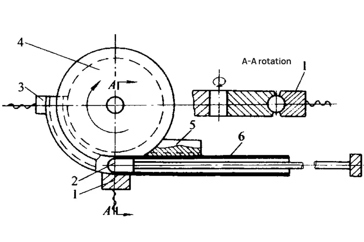
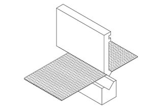
Figure 3 illustrates the structure of the lower bending die before and after springback compensation.
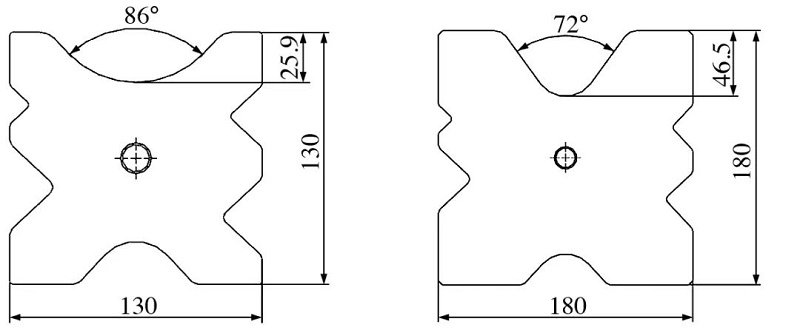
FIG. 3 Schematic diagram of the lower bending die
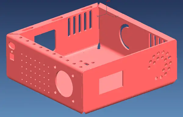
Due to modeling requirements, some bending parts have large holes near the bending line, as illustrated in Figure 4(a).
After the hole punching process is completed, the bending parts become warped near the hole, affecting the installation of other parts.
To address this issue, the method of punching out the large holes was adjusted. Part of the hole was punched out, while part of the connecting strip was retained, as shown in Figure 4(b).
After the bending process was finished, the remaining part of the hole was processed.
This method significantly improves the warping problem, enhances the flatness of the bending parts, and ensures the proper installation of parts.
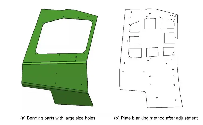
FIG. 4 Large hole blanking method for bending parts
In the bending process of BP500 material, it was discovered that the bending angles of the left and right ends of parts with long bending lines were inconsistent.
The reasons for this inconsistency are as follows:
Even when the lower bending die was rotated 180°, the angle difference between the left and right sides of the bending parts still existed, and the value had been exchanged.
Further investigation revealed that the size of the circular arc on the working bottom of the bending punch was not consistent, leading to poor parallelism between the installation undersurface and the working undersurface of the bending punch.
This resulted in inconsistent bending angles from left to right.
By reprocessing the circular arc on the working undersurface of the bending punch, the flatness was improved to 0.05 mm/m, and the problem of inconsistent bending angles between the left and right ends of the bending parts was resolved.
In conclusion, when bending a high-strength plate, it is important to determine its minimum bending radius and springback trend through experimentation.
Based on these findings, it is necessary to ensure the accuracy of the press brake, the precision of the mold, and the uniformity of the plate thickness.
Further optimization and adjustment of the press brake bending technique, such as optimizing the positioning method, can help to effectively reduce defects in the bending of high-strength plates and improve the product pass rate.

As the founder of MachineMFG, I have dedicated over a decade of my career to the metalworking industry. My extensive experience has allowed me to become an expert in the fields of sheet metal fabrication, machining, mechanical engineering, and machine tools for metals. I am constantly thinking, reading, and writing about these subjects, constantly striving to stay at the forefront of my field. Let my knowledge and expertise be an asset to your business.