The process of transforming sheet metal blanks or other profile blanks into sheet metal parts with specific angles, curvatures, and shapes through bending is known as sheet metal bending (such as bending sheets into V-shaped parts, U-shaped parts, and S-shaped parts, etc.).
The bending operation is a deformation process, widely used in stamping production. There are many methods and general/special equipment used for bending, including press bending, roll bending, draw bending, wrap bending, and roll forming.
Although the equipment and tools used in various sheet metal bending methods differ, their deformation processes, characteristics, and properties are essentially the same, sharing certain commonalities.
The process of using bending molds on a press machine to shape sheets or profiles is known as press bending. Press bending is the most widely used method of sheet metal mold bending, the main focus of this article.
Brief Overview of the Sheet Metal Press Bending Deformation Process
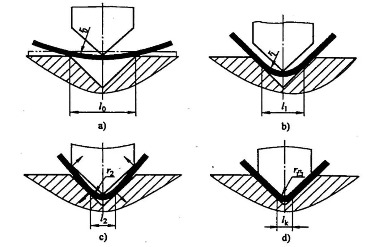
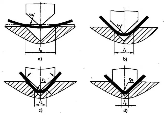
Figure 2-1 illustrates the schematic of the correction bending deformation process of the sheet in the V-shaped bending mold.
As shown in the press bending process diagram, the sheet is freely bent at the beginning stage of bending (see Figure 2-1a); as the punch presses down, the straight edge of the sheet gradually tightens against the V-shaped die working surface, and the bending radius r0 becomes r1 (see Figure 2-1b);
As the punch continues to descend, the blank bending area gradually decreases until the sheet contacts the punch at three points, at which time the bending radius changes from r1 to r2, (see Figure 2-1c); thereafter, the straight edge part of the sheet bends in the opposite direction from before, and when the stroke ends, the punch and die correct the sheet, making the sheet’s rounded corners and straight edges fully tighten against the punch (see Figure 2-1d), resulting in the desired part.
Figure 2-1 depicts the schematic of the correction of bending deformation in sheet metal within a V-shaped bending mold.
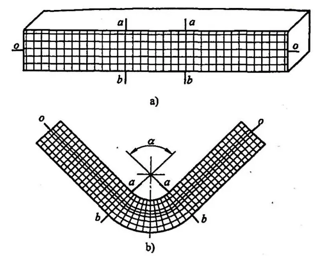
As shown in Figure 2-2, the deformation grid of the sheet metal’s side view before and after bending is illustrated. Looking at Figure 2-2, it is evident that in the flat portion of the sheet metal, the grid maintains its pre-bend state, with significant changes only within the range of the central bending angle α.
This indicates that the bending deformation primarily occurs in the area of the part’s central bending angle α. Prior to bending, the fibers aa‘=bb’. After bending, the outer longitudinal fibers bb’ are stretched (bb>bb‘), and the inner longitudinal fibers aa are compressed and shortened (aa‘<aa’).
From the inner and outer surfaces to the part’s center, each layer of fibers gradually diminishes in extent of shortening or elongation. Between the two deformation zones of shortening or elongating, there must be a layer of fibers remaining unchanged in length, referred to as the neutral layer of the part.
Figure 2-2. Deformation grid of sheet metal’s side view before and after bending
a) Grid before bending
b) Grid deformation after bending
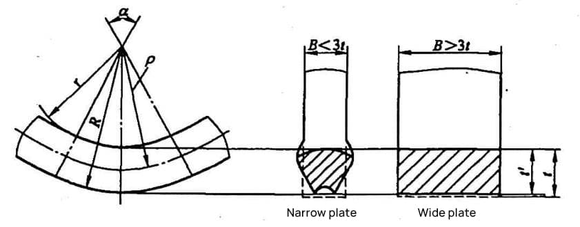
Figure 2-3 illustrates the cross-sectional deformation in the bending zone of the sheet metal. As seen from Figures 2-2 and 2-3, within the bending deformation zone, the sheet metal becomes thinner, i.e., the thickness ‘t’ thins to ‘t”, where ‘t” equals ‘ηt’ (η is the thinning coefficient).
Figure 2-3 Cross-sectional deformation schematic in the bending zone of the sheet metal
The cross-section of the sheet metal undergoes distortion. The area within the neutral layer widens transversely due to the shortening of the longitudinal fibers, while the area outside the neutral layer contracts transversely due to the elongation of the longitudinal fibers.
This distortion of the cross-section of the bent sheet metal is more prominent when bending a narrow sheet (B<3t). When bending a wide sheet (B>3t), the cross-section remains essentially unchanged, i.e., the sheet metal width does not change. It is generally considered that the width coefficient β=B’/B=1, where B is the sheet metal width, and B’ is the width after bending. To further analyze the bending phenomena, the bending deformation process of the sheet metal is discussed in three stages.
1. Elastic Bending Stage
As the sheet metal starts bending, the bending radius is at its maximum. The stress across all layers of fibers along the thickness of the sheet has not reached the yield strength, and the stress distribution follows Hooke’s law linearly. The sheet is in a state of elastic deformation, a phase referred to as the elastic deformation stage.
2. Elasto-Plastic Bending Stage
As the sheet metal is bent further, the bending radius gradually decreases, and the fibers on both sides of the sheet begin to yield and enter the plastic range. At this point, two regions of elastic deformation and plastic deformation are formed in the thickness direction of the sheet. As the degree of bending increases, the central elastic region will gradually decrease, and the plastic regions on both sides will gradually expand. This bending stage is called the elasto-plastic deformation stage.
3. Pure Plastic Bending Stage
If the degree of bending of the sheet continues to increase, corresponding to a very small bending radius, the elastic region near the neutral layer reduces to a negligible extent. It can be assumed that the entire thickness of the sheet is within the plastic range, which is why we call this the pure plastic bending stage.
As the founder of MachineMFG, I have dedicated over a decade of my career to the metalworking industry. My extensive experience has allowed me to become an expert in the fields of sheet metal fabrication, machining, mechanical engineering, and machine tools for metals. I am constantly thinking, reading, and writing about these subjects, constantly striving to stay at the forefront of my field. Let my knowledge and expertise be an asset to your business.
Basic Concepts of Computer-Aided Design and Computer-Aided Manufacturing Computer-aided design and computer-aided manufacturing (CAD/CAM) is a comprehensive and technically complex system engineering discipline that incorporates diverse fields such as computer [...]
Concept of Virtual Manufacturing Virtual Manufacturing (VM) is the fundamental realization of the actual manufacturing process on a computer. It utilizes computer simulation and virtual reality technologies, supported by high-performance [...]
A Flexible Manufacturing System (FMS) typically employs principles of systems engineering and group technology. It connects Computer Numerical Control (CNC) machine tools (processing centers), coordinate measuring machines, material transport systems, [...]
Just as manufacturing technology plays a crucial role in various fields today, nanofabrication technology holds a key position in the realms of nanotechnology. Nanofabrication technology encompasses numerous methods including mechanical [...]
Ultra-precision machining refers to precision manufacturing processes that achieve extremely high levels of accuracy and surface quality. Its definition is relative, changing with technological advancements. Currently, this technique can achieve [...]
Currently, machining can be categorized into two groups based on production batch: Among these two categories, the first one accounts for about 70-80% of the total output value of machining [...]
This article mainly introduces several mature special processing methods. I. Electrical Discharge Machining (EDM) EDM is a method of machining conductive materials by utilizing the phenomenon of electrical corrosion during [...]
What is CNC machining? Numerical Control (NC) refers to the method of controlling the movement and processing operations of machine tools using digitized information. Numerical Control Machine Tools, often abbreviated [...]
Cutting machining remains the most prominent method of mechanical processing, holding a significant role in mechanical manufacturing. With the advancement of manufacturing technology, cutting machining technology underwent substantial progress towards [...]
1. What is welding stress Welding stress refers to the stress generated during the welding process in welded components. This stress is caused by the thermal process of welding and [...]
Advanced materials refer to those recently researched or under development that possess exceptional performance and special functionalities. These materials are of paramount significance to the advancement of science and technology, [...]
Bulge forming is suitable for various types of blanks, such as deep-drawn cups, cut tubes, and rolled conical weldments. Classification by bulge forming medium Bulge forming methods can be categorized [...]