Ever wondered how aluminum transforms from a raw metal into the sturdy, versatile material we rely on daily? This article unveils the fascinating heat treatment processes behind aluminum and its alloys. You’ll learn how different methods like annealing, quenching, and aging enhance aluminum’s properties, making it essential for countless applications. Dive in to discover the science and artistry that turns aluminum into a powerhouse material!
1. Aluminum and Aluminum Alloy Heat Treatment Process
1.1 Purpose of aluminum and aluminum alloy heat treatment
The purpose is to heat the aluminum and aluminum alloy materials to a certain temperature and keep them at that temperature for a certain period of time to obtain the desired product structure and properties.
1.2 Main methods of aluminum and aluminum alloy heat treatment and their basic principles
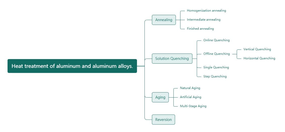
1.2.1 Classification of aluminum and aluminum alloy heat treatment (see Figure 1)
Figure 1: Classification of aluminum and aluminum alloy heat treatment
1.2.2 Basic principles of aluminum and aluminum alloy heat treatment
(1) Annealing: The product is heated to a certain temperature, kept at that temperature for a certain period of time, and then cooled to room temperature at a certain cooling rate. Through atomic diffusion and migration, the structure becomes more uniform and stable, internal stresses are relieved, and the ductility of the material can be greatly improved, although the strength will decrease.
① Homogenization annealing of ingots: The ingot is held at a high temperature for an extended period of time and then cooled at a certain rate (high, medium, low, or slow) to homogenize its chemical composition, structure, and properties. This can increase the ductility of the material by around 20%, reduce extrusion pressure by around 20%, increase extrusion speed by around 15%, and improve the quality of surface treatment.
② Intermediate annealing: Also known as local annealing or process-to-process annealing, this is done to improve the ductility of the material and eliminate internal stress from processing. It involves keeping the material at a lower temperature for a shorter period of time, in order to facilitate subsequent processing or achieve a specific combination of properties.
③ Full annealing: Also known as final annealing, this involves heating the material to a relatively high temperature, keeping it at that temperature for a certain period of time, and obtaining a softened structure in a fully recrystallized state with the best ductility and lower strength.
(2) Solution heat treatment and quenching:
This method involves heating aluminum alloy materials that can be strengthened through heat treatment to a relatively high temperature and holding them there for a certain period of time. This enables the second phase or other soluble components in the material to dissolve fully into the aluminum matrix, forming a supersaturated solid solution. The material is then cooled quickly to room temperature using a fast-quenching method. This creates an unstable state because the solute atoms are in a higher energy state and can precipitate at any time. However, the material at this stage has higher ductility and can undergo cold working or straightening processes.
① In-line quenching: For some alloys that are not highly sensitive to quenching, solution treatment can be performed during high-temperature extrusion, followed by air cooling (T5) or water mist quenching (T6) to achieve certain structures and properties.
② Off-line quenching: For highly quench-sensitive alloy materials, they must be reheated to a high temperature and kept at that temperature for a certain period of time in a special heat treatment furnace. They are then quenched in water or oil with a transfer time of no more than 15 seconds to obtain certain structures and properties. Depending on the equipment used, this can be done through salt bath quenching, air quenching, vertical quenching, or horizontal quenching.
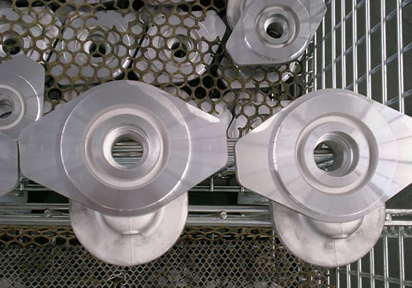
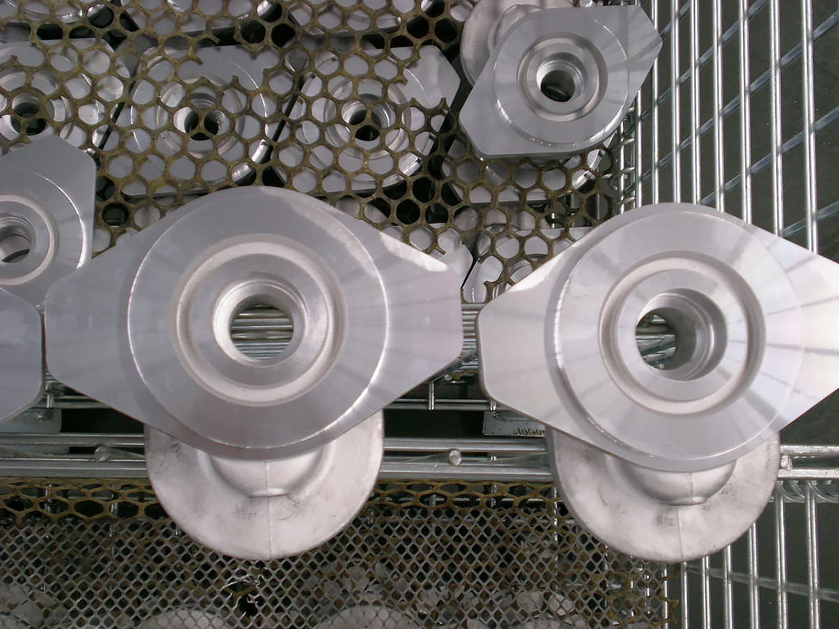
(3) Aging: After solution heat treatment and quenching, the material is held at room temperature or a higher temperature for a certain period of time. The unstable supersaturated solid solution will decompose and the second phase particles will precipitate (or settle) from the supersaturated solid solution and distribute around the alpha (AL) aluminum grains, resulting in a strengthening effect called precipitation (or settlement) strengthening.
Natural aging: Some alloys (such as 2024) can produce precipitation strengthening at room temperature, which is called natural aging.
Artificial aging: Some alloys (such as 7075) do not show obvious strengthening through precipitation at room temperature, but they do demonstrate significant precipitation strengthening at higher temperatures, which is called artificial aging.
Artificial aging can be divided into underaging and overaging:
① Underaging: This involves controlling the aging temperature to be lower and the holding time to be shorter in order to obtain certain properties.
② Overaging: This involves aging at a higher temperature or for a longer period of time to obtain special properties or better comprehensive properties.
③ Multistage aging: This involves dividing the aging process into several stages in order to obtain certain special properties and good comprehensive properties. This can be divided into two-stage and three-stage aging.
(4) Reversion treatment: This involves heating the product that has been quenched and aged to a high temperature for a short period of time in order to improve its ductility and facilitate cold bending or correcting form tolerances. This restores the product to a new quenched state.
2. Aluminum and Aluminum Alloy Product Status Notation
2.1 Basic product status codes, as shown in Table 1:
Table 1: Basic product status codes
Code
Name
Explanation and Application
F
Free processing status
It is applicable to products without special requirements for work hardening and heat treatment conditions during the forming process, and the mechanical properties of products in this state are not specified
O
Annealing state
Suitable for processed products that have undergone complete annealing to achieve the lowest strength
H
Work hardening state
It is applicable to the products whose strength is improved through work hardening. The product can go through (or not go through) additional heat treatment after work hardening to reduce the strength. The H code must be followed by two or three Arabic numerals
W
Solid solution heat treatment state
An unstable state that is only applicable to alloys that undergo solution heat treatment and natural aging at room temperature. This state code only indicates that the product is in the natural aging stage
T
Heat treatment state (different from F, O, H state)
It is applicable to the T code of products that have been (or have not been) work hardening to a stable state after heat treatment and must be followed by one or more Arabic numerals
2.2 Subdivision of H (work hardening) status
H1– Simple work hardening state. Applicable to products that have not undergone additional heat treatment and have obtained the required strength only through work hardening.
H2– Work hardening and incomplete annealing state. Applicable to products where the degree of work hardening exceeds the specified requirements for finished products and the strength is reduced to the specified target through incomplete annealing. For alloys that soften naturally at room temperature, H2 has the same minimum ultimate tensile strength value as the corresponding H3; for other alloys, H2 has the same minimum ultimate tensile strength value as the corresponding H1, but with slightly higher elongation than H1.
H3– Work hardening and stabilization treatment state. Applicable to products whose mechanical properties have been stabilized after low-temperature heat treatment or due to heating during processing after work hardening. The H3 status applies only to alloys that gradually age soften at room temperature (unless stabilized).
H4– Work hardening and painting treatment state. Applicable to products that have undergone work hardening and are incompletely annealed due to painting treatment.
The second digit after H represents the degree of work hardening of the product. The number 8 represents a hard state.
Stabilization treatment: In order to prevent the softening phenomenon that occurs after long-term storage of the alloy following cold working, the product undergoes low-temperature annealing (heating at 150℃ for 3 hours) after cold deformation. This can stabilize the mechanical properties of the alloy stored at room temperature.
2.3 Annealing (O) state code classification
2.3.1 O1- Homogenization annealing.
2.3.2 O2- Incomplete (partial) annealing of the product.
2.3.3 O3- Complete annealing of the product.
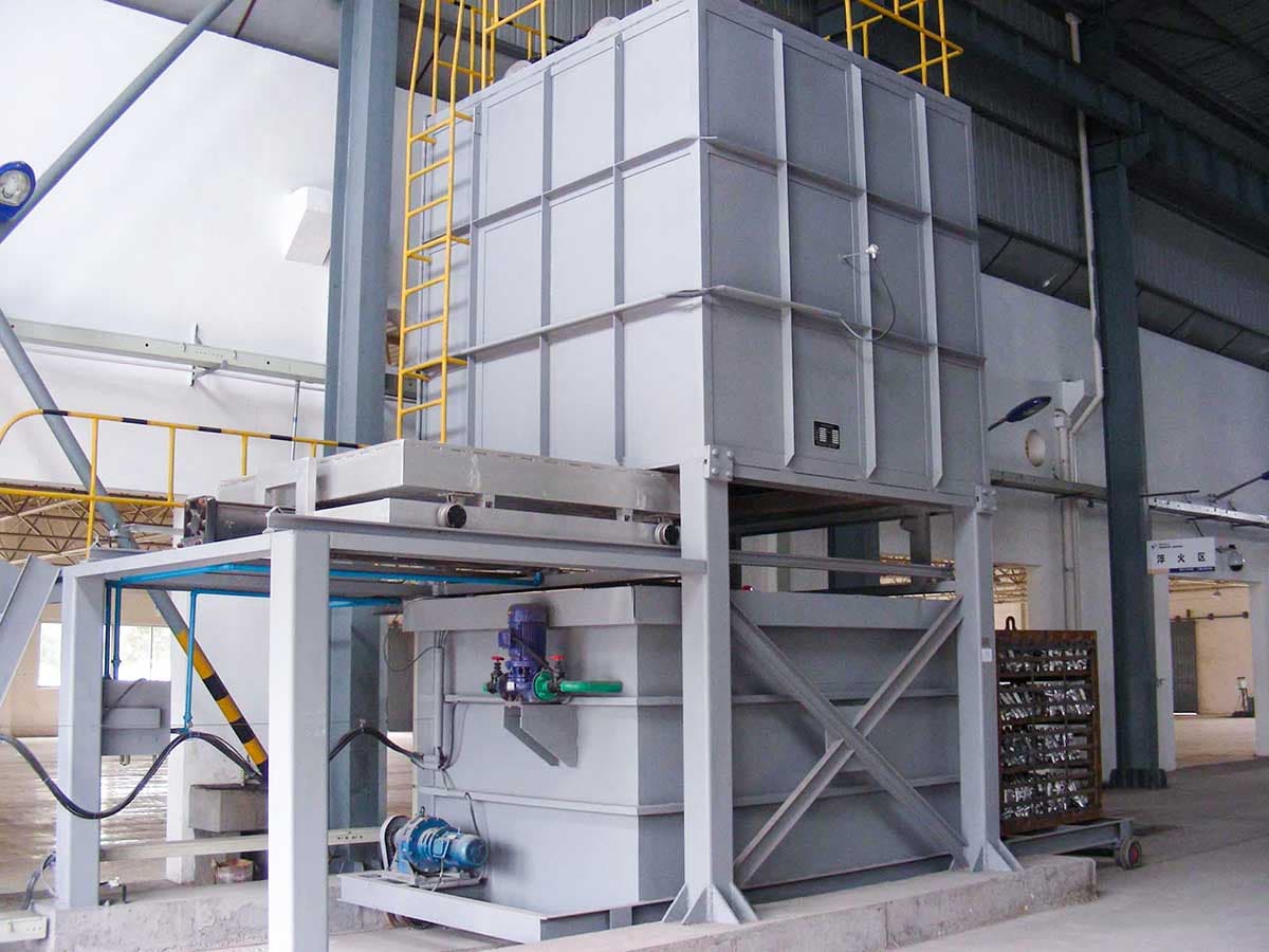
3. Temperatures Control Table for Aging Furnace Process
Combustion chamber:
Set temperature on temperature control table: 200-215℃
Displayed temperature on temperature control table: 190-210℃
Measured temperature inside furnace: 200-210℃
Rear right fan: Set temperature for fan: 160-180℃
Displayed temperature on fan meter: 200-210℃
Controlled temperature inside the furnace: 200-210℃
Display: Displayed temperature on temperature control table: 190-205℃
Measured temperature inside furnace: 200-210℃
Display: Displayed temperature on temperature control table: 195-210℃
Measured temperature inside furnace: 200-210℃
4. Aging Furnace Energy Calculation
Motor (electric energy loss)
Burner (fuel loss)
Energy consumption for heating (cooling furnace, heating furnace)
Energy consumption for insulation
Insulation time Aging furnace failure (affects process hardness)
Motor power: 40/55W/h, current: 81/98A, voltage: 380V, speed: 740/1480r/min
Multi-speed three-phase asynchronous motor with model YD2808-8/4.
Power distribution for aging furnace
Model XL-21, rated voltage: 380V, rated current: 1A.
Question: The aging process of the aging furnace was only classified according to the alloy status, but there are no clear specifications for different wall thicknesses of the same alloy. What is the maximum difference in wall thickness that can be aged together?
5. How to Adjust the Air Flow at the Extrusion Outlet?
When the material at the extrusion outlet curls upwards, it is necessary to appropriately reduce the upward air speed or close the upper fan; when the material at the extrusion outlet curls downwards, it is necessary to appropriately reduce the downward air speed or close the lower fan.
6. Guidelines for Executing the Aging Process (For Aging Furnace No. 3 in the Fourth Plant)
Based on data collected during an investigation of the process for this furnace, adjustments will be made to the temperature control parameters during operation.
Aging process
Executive Rules
Alloy state
Holding time ℃
Insulation time h
Insulation time (based on wall thickness) h
Holding time temperature
1.0mm
1.0-4.0mm
4.0-30mm
Fan temperature control meter
Combustion engine temperature control table
T6
175±8
8
8
8
10
171
171
T5
200±8
2
2
2.5
3
197
197
T52
235±8
1.5
1.5
2
1
230
230
Note:
When at least two temperature control tables (fan and burner) have reached the set temperature, the insulation time starts to be calculated.
The determination of insulation time is based on the maximum wall thickness of the profiles inside the furnace.
For profiles with a higher basket density, it is necessary to appropriately extend the insulation time.
The aging process for 6005-T5, 6005A-T5, and T6511 states are all carried out in accordance with the T6 system.
If adjustments need to be made to the aging process for specific varieties, follow the instructions from the process department.
When using double cavity molds for extrusion, attention must be paid to adjusting the flow rate of each hole to ensure consistency. During extrusion, aluminum flow problems in the ingots should be monitored.
To master the GB-5237 standard, it is important to understand twist, tolerances, and be able to use reference tables. In addition, it is crucial to be proficient in identifying bubbles at the beginning and end of flat die profiles, and to note that combination dies, especially for pipes, may have fewer bubble issues.
7. Precautions for Extrusion
7.1 For 6xxx series alloys, mechanical properties cannot be guaranteed at temperatures below 500℃ and surface quality is poor above 560℃.
7.2 Generally, the relationship between extrusion speed and temperature is as follows: high speed at low temperature, low speed at high temperature. The extrusion speed should be increased as much as possible, with temperatures set at the lower limit in the table, but the outlet temperature must meet the specified requirements.
7.3 For molds with large extrusion parameters, especially those with many runner holes, the mold and aluminum rod temperatures should be set to the upper limit. However, the speed should be reduced in the later stages of extrusion.
7.4 For special heat sink profile molds, the mold temperature should be above 480℃ and the aluminum rod temperature should be above 530℃.
7.5 Mechanical performance standards vary across different countries and are related to the cross-section of the profiles. If the mechanical performance does not meet the requirements in the table, technical personnel should refer to relevant national standards or communicate with the customer to determine whether it is qualified or should be released. Mechanical performance can be executed according to technical agreements if there are specific user requirements.
8. Polishing Materials
6463-T5 homogeneous rods should be extruded at low temperature and high speed (460-480℃).
8.1 Surface mechanical scratches caused by molds are a common issue.
8.2 Problems such as cutting and transfer segmentation causing scratches, abrasions, white lines, bright lines, shrinkage marks, wool pulling, edges, waves, twisting, geometric dimensional deviations, false scratches, and orange peel often occur.
9. Surface Mechanical Treatment of Aluminum
The surface effect after treatment can be divided into: a. Bright surface b. Semi-matte surface c. Matte surface
The principle of polishing is to remove the protruding parts by creating plastic deformation on the surface of the material through mechanical grinding, thereby obtaining a smooth and polished surface. Generally, cloth wheels, wool wheels, sandpaper, etc. are used.
The polishing process is generally divided into three steps: rough polishing, medium polishing, and fine polishing.
Rough polishing: Polishing the surface with a hard wheel, which has a certain abrasive effect on the substrate that has or has not been polished
Medium polishing: Using a harder polishing wheel for further processing after rough polishing, it can remove the scratches left by rough polishing
Fine polishing: The last step of polishing, using a soft wheel to obtain a mirror-like surface with bright light, and has little effect on substrate grinding.
10. Mechanical Drawing Method
10.1 Straight line drawing refers to the method of processing straight lines on the surface of an aluminum plate by mechanical friction.
10.2 Random drawing is a kind of matte wire pattern obtained by moving the aluminum plate back and forth under a rotating copper wire brush.
10.3 Spiral polishing, also known as spin polishing, is a wire pattern obtained by rotating and polishing the surface of an aluminum or aluminum alloy plate with a cylindrical felt or corundum nylon wheel mounted on a drill and mixed with polishing grease thinned with kerosene.
10.4 Threaded drawing is done using a machine.
11. Analysis of Polishing Material Problems
11.1 Why are there heavy mechanical scratches in low-temperature and high-speed extrusion?
This may be due to scraping of the mold surface during filling and the initial laminar extrusion phase, resulting in heavy mechanical scratches during later extrusion.
11.2 Why are there still defects such as mechanical scratches in high-temperature and low-speed extrusion?
This may be due to a high rod temperature, which causes severe turbulence during extrusion, causing a large number of oxide and impurities on the surface of the ingot to flow towards the center, making the surface of the profile not good.
12. Mold
12.1 Combination molds are divided into two types according to their structure: bridge-type combination molds and runner-type combination molds. Bridge-type combination molds are commonly known as tongue-shaped molds, while runner-type combination molds are simply called combination molds.
12.2 Tongue-shaped molds require lower extrusion force and are suitable for extruding hollow profiles of alloys that are not easily deformed and have small inner holes.
12.3 Combination molds are suitable for extruding large and medium-sized hollow profiles with complex shapes and larger inner cavity dimensions made from alloys that are easily deformed.
12.4 The hollow profiles extruded using combination molds show obvious welds in their macrostructure, and the number of welds is equal to the number of metal strands into which the ingot is divided.
12.5 To obtain high-quality welds, the pressure inside the mold should be increased, and a slightly larger extrusion coefficient should be selected. It is advisable to use a higher extrusion temperature, and the extrusion speed should not be too fast.
12.6 When inspecting hollow profiles, their surface quality, geometric dimensions, mechanical properties, and internal structure are the same as ordinary profiles. However, for hollow profiles used in important parts, their weld quality must be inspected, and the cut length should not be less than 500-1000mm.
13. Casting Ingots
13.1 Typical crystal structures of aluminum alloy ingots include fine crystal bands on the surface, columnar crystal bands, and equiaxed crystal bands in the center.
13.2 In aluminum alloy ingots, there are three common shapes of aluminum solid solution grains:
a. Equiaxed crystals in a granular shape
b. Columnar crystals in an elongated shape
c. Feathery crystals in a thin sheet shape.
13.3 Under constant alloy composition and other conditions, the width of the columnar crystal region increases with the increase of casting temperature. The size of equiaxed grains decreases as the casting temperature decreases. When the casting temperature is constant, the columnar crystal region decreases with the increase of alloy element content.
13.4 Refining treatment: It is a process of increasing the dispersion of the metal or alloy structure and improving its organization with a small amount of special additives (refining agents). It is also called refinement treatment or incubation treatment.
14. Wall Thickness Technical Requirements
14.1 Oxide wall thickness
a. Acid sand oxidation: ±0.1mm required
b. Silver-white oxidation: ±0.1mm required
c. Polished oxidation: ±0.1mm required
d. Sandblasting oxidation: -0.08 to +0.1mm required
e. Twist pattern oxidation: -0.08 to +0.1mm required
f. Alkali etching oxidation: -0.05 to 0.15mm required
14.2 Electrophoretic wall thickness
a. Flat electrophoresis: ±0.1mm required
b. Sandblasting electrophoresis: ±0.1mm required
c. Colored alkali-etching electrophoresis: -0.05 to +0.1mm required
14.3 Spray coating wall thickness
a. General spray coating: -0.15 to +0.05mm required
b. Wrinkle spray coating: -0.15 to +0.05mm required
c. Woodgrain spray coating: -0.15 to +0.05mm required
d. Fluorocarbon spray coating: -0.12 to +0.07mm required
14.4 Export substrate wall thickness
a. The wall thickness tolerance specified on the drawing is executed.
b. If the wall thickness tolerance is not specified, the national standard wall thickness tolerance column 2 is executed.
c. For completely enclosed hollow profiles, the national standard wall thickness tolerance column 3 is executed (except for SOMA series round tubes).
Note: The wall thickness tolerance marked on the drawing and the production plan is the tolerance of the finished product. The wall thickness tolerance of the extruded substrate should be adjusted according to the different surface treatment methods.
15. Key Points for Metallographic Grinding
For aluminum, generally start with 0 grit sandpaper and then move to 400#, 600#, 800#, 1000#, 1200#. During the grinding process, one type of sandpaper is used in one direction.
When switching to the next sandpaper, the grinding direction should be perpendicular to the previous one, which is beneficial for observing whether there are deep scratches from the previous grinding phase.
To prevent hard particles or large pieces of metal from peeling off during grinding, a thin layer of wax can be applied to the sandpaper. This makes the grinding soft and produces a better metallographic surface. When grinding, sit correctly and apply even force. The sample should be square and flat.
16. Electrolytic Polishing
H2SO4, HNO3, and HF are mixed, and an L-shaped cathode made of stainless steel or aluminum plate is used. An appropriate voltage is selected according to the size of the sample. The voltage and polishing time must be strictly controlled during electrolytic polishing, generally around ten seconds.
After polishing, rinse with clean water, then ethanol, and then use dilute nitric acid to remove corrosion products from the surface, followed by rinsing with clean water and air-drying.
17. High Magnification Electron Metallographic Microscope
The magnification can reach 1000 times. The coarse focusing knob is on the left, and the fine focusing knob is on the right, at the top of the horizontal moving device and power switch. There is a ruler on the eyepiece on the right side to accurately position the tissue and phase. The tracker on the right can be used directly for photography.
When processing photos, debris should generally be removed. Vibration of the workbench or body during operation can cause the observed and photographed phases to appear blurry. For tissue analysis, there are generally many dendrites in each grain, and different amounts of precipitation are present at the grain boundaries. After sample corrosion with mixed three-strong acid, aluminum matrix appears as white, the precipitated phases appear as black-gray, and the grain boundaries appear as gray lines in the field of view.
18. Process Flow Chart for Casting
Incoming inspection → batching → cold furnace preheating → loading furnace → melting → skimming → sampling and testing of melting furnace → refining → sampling and testing of holding furnace → refining skimming → holding → casting → inspection of round ingots → cutting into size bar → sequencing
19. Grain Size Grading Standard
Grade 1, grain size ratio 1:1, average grain area 0.026mm2
Grade 2, grain size ratio 1:1, average grain area 0.40mm2
Grade 3, grain size ratio 1:1, average grain area 1.20mm2
Grade 4, grain size ratio 1:1, average grain area 2.60mm2
Grade 5, grain size ratio 1:1, average grain area 8.0mm2
Grade 6, grain size ratio 1:1, average grain area 16mm2
Grade 7, grain size ratio 1:1, average grain area 36mm2
Grade 8, grain size ratio 1:1, average grain area 80mm2
20. Appendix to the Process Supervision and Inspection System of the Foundry
As the founder of MachineMFG, I have dedicated over a decade of my career to the metalworking industry. My extensive experience has allowed me to become an expert in the fields of sheet metal fabrication, machining, mechanical engineering, and machine tools for metals. I am constantly thinking, reading, and writing about these subjects, constantly striving to stay at the forefront of my field. Let my knowledge and expertise be an asset to your business.
Attention all mechanical engineers and manufacturing professionals! Are you struggling with pesky anodizing defects in your aluminum products? Look no further! In this blog post, we'll dive deep into the…
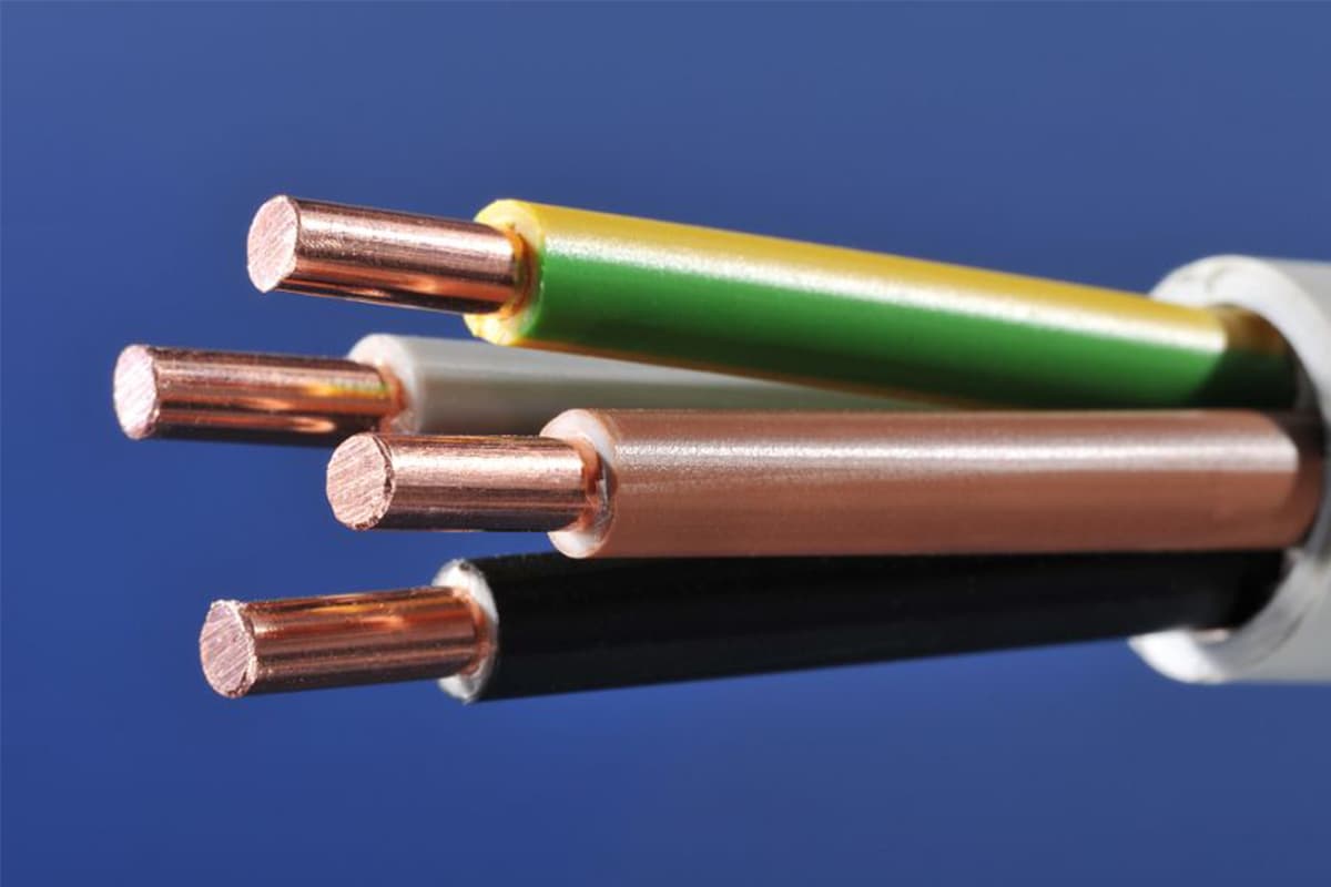
Ever wondered why connecting copper and aluminum wires is problematic? This article explains the risks associated with connecting these two metals due to their differing electrochemical properties, which can lead…
Have you ever wondered which cable is better: copper or aluminum? This article dives into a detailed comparison of copper and aluminum cables, highlighting their advantages and disadvantages. From resistivity…
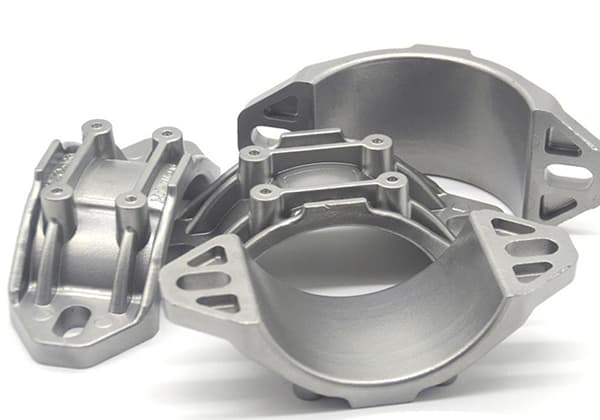
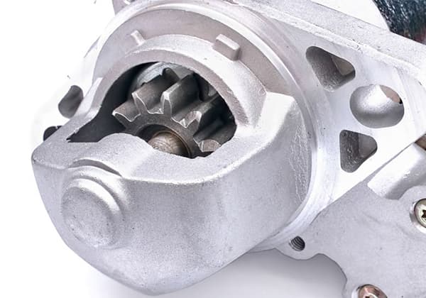
Have you ever wondered what makes your car's engine parts so durable and efficient? This article unveils the secrets behind casting aluminum alloys, the unsung champions of automotive engineering. Learn…
Have you ever wondered why cracks appear in metal parts during manufacturing? In this insightful blog post, we'll dive into the intriguing world of forging cracks, heat treatment cracks, and…
Have you ever wondered how to choose the right aluminum alloy for your project? With a vast array of options, each with unique properties, it can be a daunting task.…
Why do motor bearings get so hot, and what can be done about it? This article dives into the causes of motor bearing heat generation, from excessive loads and poor…
What’s the real difference between cast aluminum and die-cast aluminum? This article dives into the distinct manufacturing processes and properties that set these two types of aluminum apart. From the…
Aluminum alloy has high specific strength, good corrosion resistance, high toughness and easy processing. It is widely used in various high-strength structural parts of aircraft, missiles and rockets. It is…