A narrow and long workpiece is characterized by its large length-to-width ratio and is positioned using its short edge during bending.
The common problem of workpieces being out of tolerance is often caused by the limited contact size between the positioning edge of the workpiece and the backstop positioning of the press brake machine.
This post introduces a tooling structure designed to optimize the bending and positioning of narrow and long workpieces, effectively addressing the challenges of difficult positioning and low precision.
With advancements in sheet metal deformation technology, the CNC press brake has become a crucial production equipment for sheet metal cold deformation processing, widely used in the sheet metal processing industry.
For safety and convenience, most press brakes currently use rear stop fingers as the positioning device. After simple programming, the rear stop linkage, single action, and other functions can be achieved, meeting the processing requirements for bending parts of various shapes.
However, the rear stop positioning used in CNC press brakes also has its limitations. When the width of the positioning edge of the workpiece being processed is too narrow (such as in the case of a narrow and long workpiece), the limited contact size between the workpiece and the rear stop finger leads to problems such as inaccurate positioning size, dislocated bending position and design bending line, resulting in poor quality products, frequent rework and repair, and significant waste of materials, energy, and labor.
Bending deformation mechanism
In production, it is often necessary to bend a workpiece (steel plate) into a specific angle, where the bending radius at the bending position is small.
This process is known as bending.
Bending is the process of using a punch and die to apply an external force to the sheet metal, shaping it into a specific angle or form.
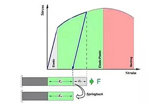
The bending deformation of the workpiece is divided into several stages.
Initially, the material is in a state of free bending.
As the top punch is pressed down, the material gradually moves closer to the surface of the lower die.
Then, as the punch continues to press down, the bending area of the material becomes smaller until it makes contact with the punch at three points.
When the punch reaches the lowest point of its stroke, the material is completely in contact with the punch.
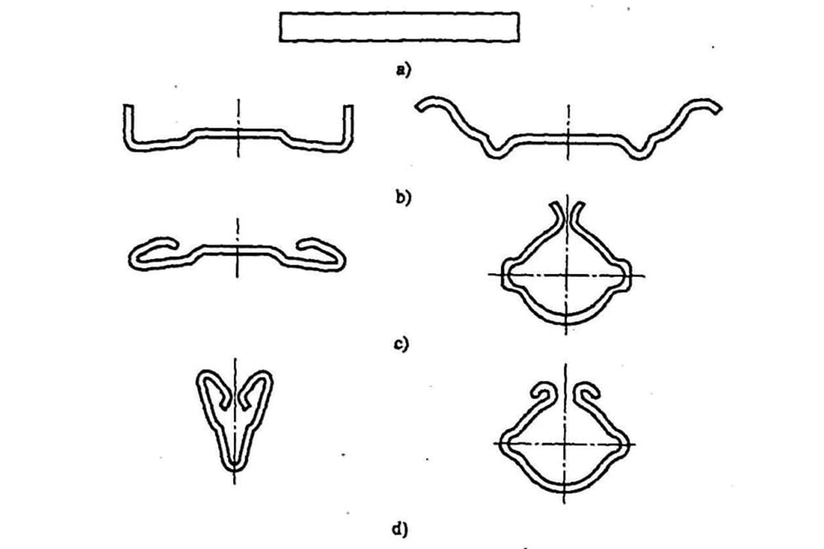
During free bending, the inner fibers of the material shorten due to longitudinal compression and the outer fibers elongate due to longitudinal tension, resulting in transverse shortening due to constant volume during plastic deformation.
Therefore, for workpieces with a narrow width, the cross-section will have a slight fan-shaped appearance after bending.
For wide plate workpieces, the bending cross-section will not exhibit any noticeable deformation.
Bend positioning
Basic positioning of press brake
The CNC press brake typically uses stop fingers for workpiece positioning.
The basic principle is that before bending processing, a bending program is prepared and the workpiece shape is input into the machine controller. The machine then calculates the bending line position of the workpiece, and the CNC system controls the servo motor to move the two rear stops to the required bending positioning position through the high-precision lead screw.
The operator only needs to align the positioning edge of the workpiece with the stop finger of the press brake to complete the positioning process.
At this point, the center line of the lower die of the press brake represents the workpiece’s bending line.
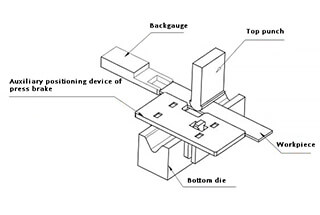
The workpiece positioning state is illustrated in Figure 1.
Fig. 1 Workpiece positioning
Limitations of the positioning device of press brake
During the production process, it was discovered that using the typical rear stopper positioning employed by the current bending machine can result in difficulties aligning the workpiece with the rear stopper if the size of the positioning edge between the workpiece and the rear stopper is too short.
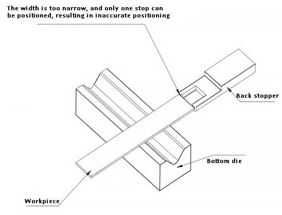
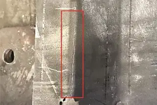
As illustrated in Figure 2, a small left-right offset of the workpiece can cause incorrect positioning, resulting in either the over-tolerance scrapping of the workpiece or an uneven edge size during bending.
Fig. 2 Positioning of narrow and long workpiece
Operators are required to repeatedly align the workpiece in order to achieve the desired primary forming effect, however, this frequently leads to subpar results and has a significant negative impact on both production efficiency and product quality.
Positioning optimization of narrow and long workpiece machining
Structure of positioning optimization device
Considering the limitations of the positioning device of the CNC press brake, a new positioning optimization device has been designed and is depicted in Figure 3.
Fig. 3 Positioning optimization device
The back plate is utilized to close to the side of the bending machine’s lower die. The movable locking block is used in conjunction to securely lock the device onto the lower die of the bending machine. The front plate serves as the location for the screw installation, and the locking screw fixes the movable locking block onto the lower die. The positioning top plate is utilized for the purpose of positioning the workpiece.
Use of positioning optimization device
To use the above-mentioned positioning optimization device, it must first be aligned and clamped onto the bending machine’s lower die and its state should be checked using a square.
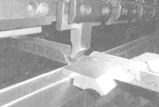
When positioning the workpiece, the end of the workpiece should be positioned close to the rear stop of the bending machine, while the side of the workpiece should be positioned using the positioning optimization device, resulting in accurate and stable positioning of the workpiece, as illustrated in Figure 4.
Fig. 4 Matching of rear retaining material and auxiliary positioning device
Implementation effect of the auxiliary positioning device
(1) Improved Production Efficiency:
Prior to the use of this device, narrow and long workpieces often required repeated measurements to ensure accurate positioning, leading to large errors. However, with the use of this device, the operator can easily locate the workpiece to be processed, significantly improving production efficiency and reducing production and processing time for a single workpiece by more than half.
(2) Improved Product Quality:
Before the implementation of this tooling, the defective rate of narrow and long workpieces remained high, and issues such as over-tolerance scrapping and uneven bending edge size were prevalent. However, with the use of the optimization device, these problems caused by inaccurate positioning during bending no longer occur, leading to a significant improvement in product quality.