Steel Bending Crack: Factors and Improvement Measures
Ever wondered why steel sometimes cracks during bending? In this article, we explore the fascinating world of steel bending technology, uncovering the reasons behind common defects like corner and central cracking. Discover how proper techniques and material quality can make all the difference in preventing these issues. Get ready to learn practical insights that can enhance your understanding and application of steel processing!
Bending processing technology is a type of steel processing technology that is widely used in various fields such as automobile manufacturing, engineering machinery, bridges, ships, and construction.
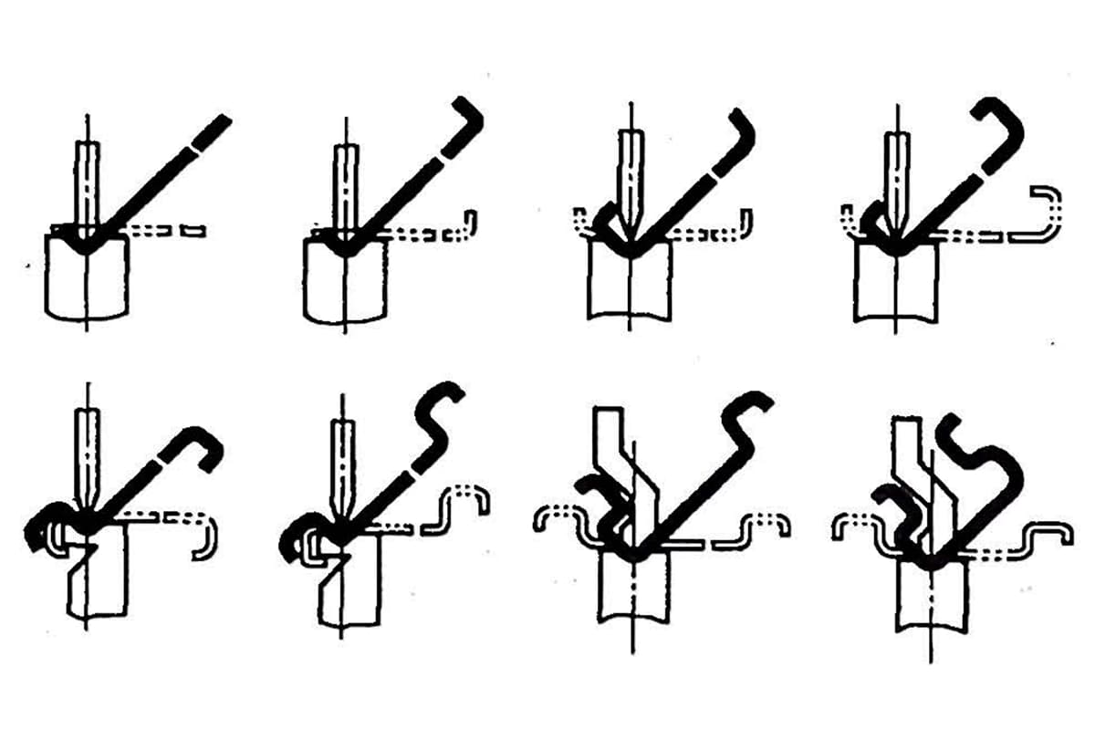
Under the pressure of the upper or lower die on the bending machine, the metal sheet undergoes elastic deformation first and then plastic deformation.
In the beginning stage of plastic bending, as the upper or lower die bends the sheet metal, the sheet metal gradually fits tightly against the inner surface of the V-groove of the upper or lower die, while the curvature radius also gradually decreases.
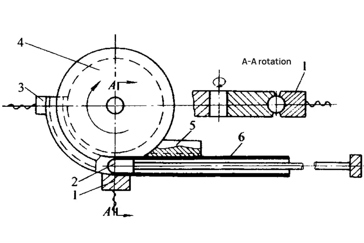
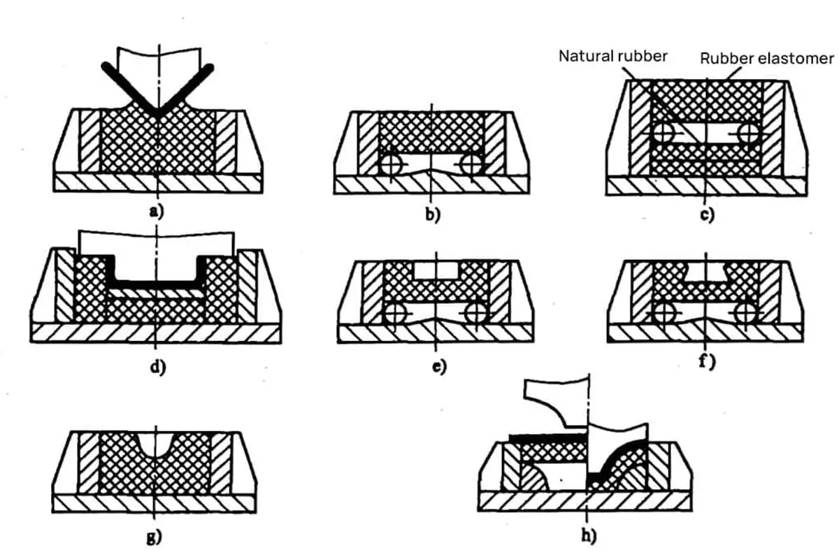
As the pressure continues until the end of the stroke, the upper and lower dies come into full contact with the sheet metal, forming the V-shaped bend, which is commonly processed using bending machines and rolling equipment.
Bending cracking is a major defect in the use of steel processing. According to the location of the cracking, it can be divided into corner cracking and central cracking.
The factors that cause cracking include improper processing technology and material quality defects, which have a negative impact on steel production enterprises.
Researchers analyzed, summarized, and studied typical quality cases and referred to relevant materials to analyze various factors that cause bending cracking and propose improvement measures.
Typical samples of bending, cracking, and physical-chemical testing
1.1 Corner Crack Samples
1.1.1 Macroscopic Morphology
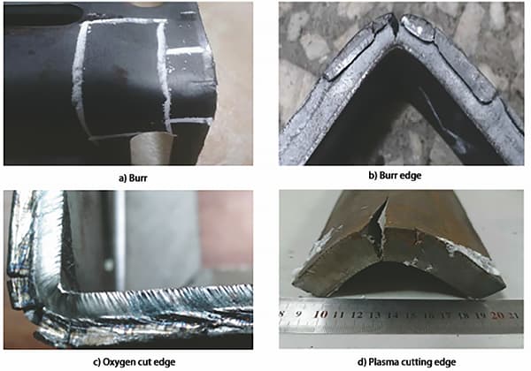
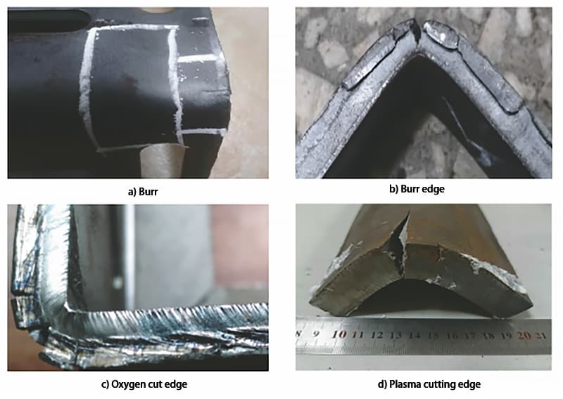
Corner cracking is the most common type of defect in bending cracking, and there are usually burrs, rough edges, oxygen cutting edges, or plasma cutting edges at the corner cracking position. If the edge of the workpiece is not sandblasted or incompletely treated during bending processing, corner cracking will occur, and the cracks at the corner cracking are usually short and located in the work-hardened area of the corner.
Typical defects of Q235B steel and Q355B steel were selected for analysis, and the macroscopic morphology of corner cracking is shown in Figure 1.
Figure 1: Macroscopic appearance of steel corner cracking.
1.1.2 Chemical Composition Analysis
Four typical corner crack samples of Q235B steel and Q355B steel were selected for chemical composition analysis, and the results met the requirements.
1.1.3 Mechanical Property Testing
The mechanical properties of the above four typical corner crack samples of Q235B steel and Q355B steel were tested, and the results are shown in Table 1 (D is the bending diameter, a is the sample thickness), and the results met the requirements.
Table 1: Mechanical performance test results of Q235B and Q355B steel samples with corner cracking
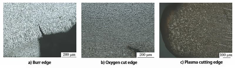
Metallographic examination was carried out on the cracking positions of the above four typical corner crack samples of Q235B steel and Q355B steel, and the results are shown in Figure 2. As can be seen from Figure 2, there is grain cold deformation in the tissue at the cracking position, and there is a thermal influence structure at the oxygen cutting and plasma cutting cracking position.
Figure 2: Common appearance of samples with corner cracking.
1.2 Bending Crack Samples
1.2.1 Macroscopic Morphology
Central cracking often manifests as non-continuous cracking in the middle of the workpiece, and the cracks are usually long, with some instances of short cracks. The macroscopic morphology of central cracking is shown in Figure 3.
Figure 3: Macroscopic appearance of samples with center cracking.
1.2.2 Chemical Composition Analysis
Six typical central crack samples of Q235B steel, Q355B steel, and 610L steel were selected for chemical composition analysis, and the results met the requirements.
1.2.3 Mechanical Property Testing
The mechanical properties of the above six typical central crack samples of Q235B steel, Q355B steel, and 610L steel were tested, and the results are shown in Table 2, and the results met the requirements.
1.2.4 Metallographic Examination
Metallographic examination was carried out on the above six typical central crack samples of Q235B steel, Q355B steel, and 610L steel, and the results are shown in Figure 4.
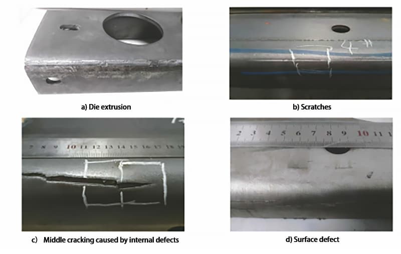
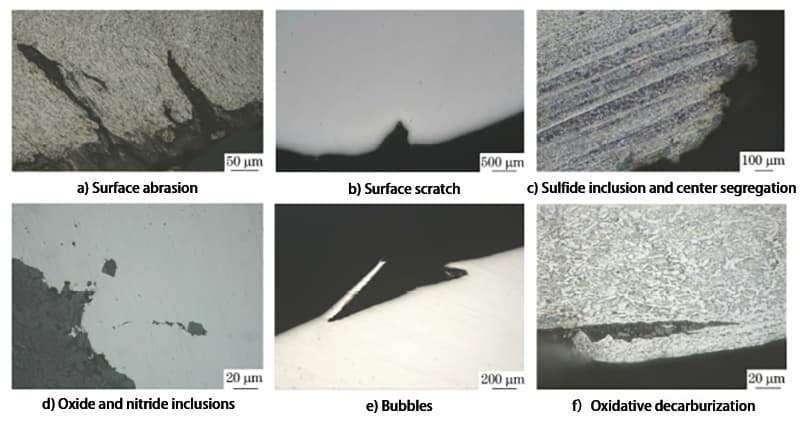
Figure 4: Microscopic appearance of the specimen with center cracking.
As can be seen from Figure 4, there is grain cold deformation at the grinding tool extrusion position, and scratch openings can be seen at the root of longer and straighter cracks. The samples also contain clustered sulfide inclusions, center segregation, high-temperature oxidation particles, decarburization due to oxidation, and bubble features.
Analysis of the causes of bending cracking defects
2.1 Improper processing techniques
2.1.1 The influence of bending diameter
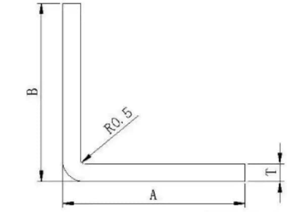
When bending steel, the outer layer of the bent area undergoes tension while the inner layer undergoes compression. When the material thickness is constant, the smaller the bending radius, the more severe the tensile and compressive stresses on the material. If the tensile stress at the outer corner exceeds the material’s ultimate strength, cracking or fracture will occur, mainly at the middle of the workpiece and sometimes at the corners.
2.1.2 The influence of bending tools
If the V-grooves of the bending tools are rough, the workpiece will be subjected to uneven forces when passing through the bending machine, causing surface wear or local pressure, leading to surface defects, followed by extrusion cracking. The cracks usually appear straight and long, with visible cold deformation of the grains at the crack roots.
2.1.3 The influence of logistics
During steel transportation and loading and unloading, surface scratches may occur, which destroy the continuity of the substrate surface. Cracking is prone to occur at the scratched area during bending. These cracks are usually longer and straight, with visible scratch openings at the root of the crack.
2.2 The influence of material defects
2.2.1 The influence of harmful elements, inclusions, and gases in steel
During the smelting process, high sulfur and phosphorus content in steel leads to high sulfide inclusion content or, even if the overall content does not exceed the standard, these elements aggregate locally and cause serious central segregation at the inclusions. This leads to a decrease in the steel’s plasticity and toughness, making it susceptible to bending and cracking.
In addition, microcracks on the surface of the ingot are oxidized at high temperatures during rolling, and the high oxygen and nitrogen content in the steel, especially the nitrogen element, easily forms TiN with titanium. The TiN particles precipitated along the grain boundaries during continuous casting can cause original cracks in the billet, which can lead to cracking during bending.
2.2.2 The influence of steel surface quality
Microcracks and air holes on the surface of the steel are prone to cracking at the crack site under stress after bending. Multiple small cracks can be visible at the bend arc with the naked eye.
2.2.3 The influence of mechanical properties and anisotropy of steel
The better the plasticity of the material, the more stable the plastic deformation, and the larger the elongation at break, the better the bending performance. Even if the bending diameter is small, it is not easy to crack.
In addition, the longitudinal and transverse properties of steel are different, and the longitudinal banded structure is more severe than the transverse. This means that the longitudinal plasticity index of the steel is higher, so when bending along a direction perpendicular to the rolling direction, the bending performance of the steel is better and less prone to cracking compared to bending along the transverse direction.
Improvement measures
(1) Solutions to the cracking problem caused by burrs, sharp edges, and oxygen cutting in corner areas: manually sand and round the burrs and sharp edges, or use a deburring machine to automatically remove them and eliminate the hardened processing area to reduce the cracking rate.
Change the bending process to continuous roll forming, then cut after forming to avoid the hardened processing caused by cutting. Remediate minor defects through subsequent welding processes.
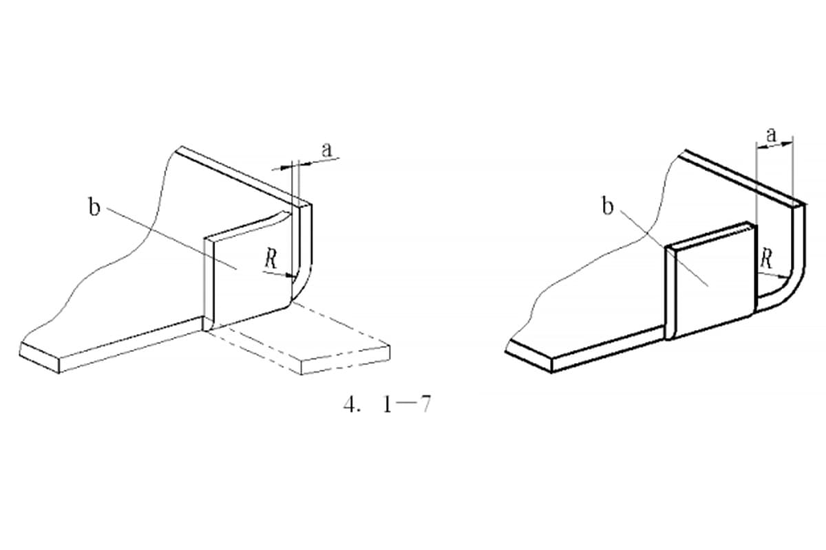
(2) To address the issue of small bending radii, the R angle should be enlarged within the allowable range of the design to avoid too small of a bending radius.
(3) Avoid surface scratches during the logistics process of transporting and unloading steel materials.
(4) In the steelmaking process, improve the purity of the steel, reduce the content and aggregation of inclusions in the steel. The argon blowing process should be fully utilized to ensure that larger sulfides in the steel are completely floated and separated.
The appropriate flow field should be maintained during the steel flow process to ensure the proper and stable flow field in the crystallizer, which can further remove inclusions in the steel while preventing contamination from slag entrapment.
Reasonably control the casting temperature, pulling rate, and cooling rate during continuous casting. Proper use of the lightweight pressing technology and electromagnetic stirring technology can improve the internal quality of the billet, reduce center segregation, and prevent the formation of centerline cracks.
(5) In the rolling process, strengthen the control of heating, rolling temperature, and post-rolling cooling processes, avoid the formation of abnormal structures such as bainite, martensite, coarse grains, and mixed crystals, and reduce strength within the allowable range of product standards while improving plasticity and toughness.
As the founder of MachineMFG, I have dedicated over a decade of my career to the metalworking industry. My extensive experience has allowed me to become an expert in the fields of sheet metal fabrication, machining, mechanical engineering, and machine tools for metals. I am constantly thinking, reading, and writing about these subjects, constantly striving to stay at the forefront of my field. Let my knowledge and expertise be an asset to your business.
Have you ever faced challenges with bending stainless steel plates? This article unravels the complexities of stainless steel bending, from the force required to the impact of spring back. Learn…
Have you ever considered the forces at play when bending a pipe? In this article, we'll explore the fascinating world of pipe bending mechanics. Our expert mechanical engineer will break…
Have you ever wondered how sheet metal parts are designed and manufactured with precision? In this blog post, we'll dive into the fascinating world of bend allowance - a crucial…
Are you struggling to design accurate sheet metal parts? Unlock the secrets of the K-factor, a crucial concept in sheet metal fabrication. In this article, our expert mechanical engineer demystifies…
How does the distance between a flanged hole wall and a bending edge affect the integrity of a metal part? In metalworking, this gap is crucial to prevent damage during…
Have you ever wondered why sheet metal parts crack or deform during bending? This article explores the essential principles of sheet metal design, focusing on bending techniques to ensure precision…
Have you ever wondered how intricate the designs of bending dies can get? This article dives into the structural designs of common bending dies, from V-shaped to Z-shaped, explaining their…
How do you achieve precise bends in sheet metal? Understanding the molds and techniques behind this process is crucial. This article delves into various bending methods, from free bending to…
Attention all sheet metal fabricators and designers! Are you struggling to determine the optimal bending radius for your projects? Look no further! In this blog post, we'll dive into the…