The 15 Best Laser Welding Machine Manufacturers in 2024
In the rapidly evolving world of laser welding, innovation is key. As manufacturers push the boundaries of what's possible, a handful of companies stand out as leaders in the field.…
How does the focus of a laser impact the quality and effectiveness of welding? This intriguing question delves into the critical relationship between laser defocus and welding performance. By exploring various focus settings, the article reveals how beam distribution, solder joint size, penetration depth, and tensile strength are all influenced by defocus adjustments. Readers will gain a deeper understanding of optimizing laser welding processes for better precision and strength in their projects.
Laser technology is one of the four major technological breakthroughs of the 20th century, alongside computers, semiconductors, and atomic energy technologies. Over the years, it has been widely adopted in the fields of optical communications, medical treatments, testing, and material processing.
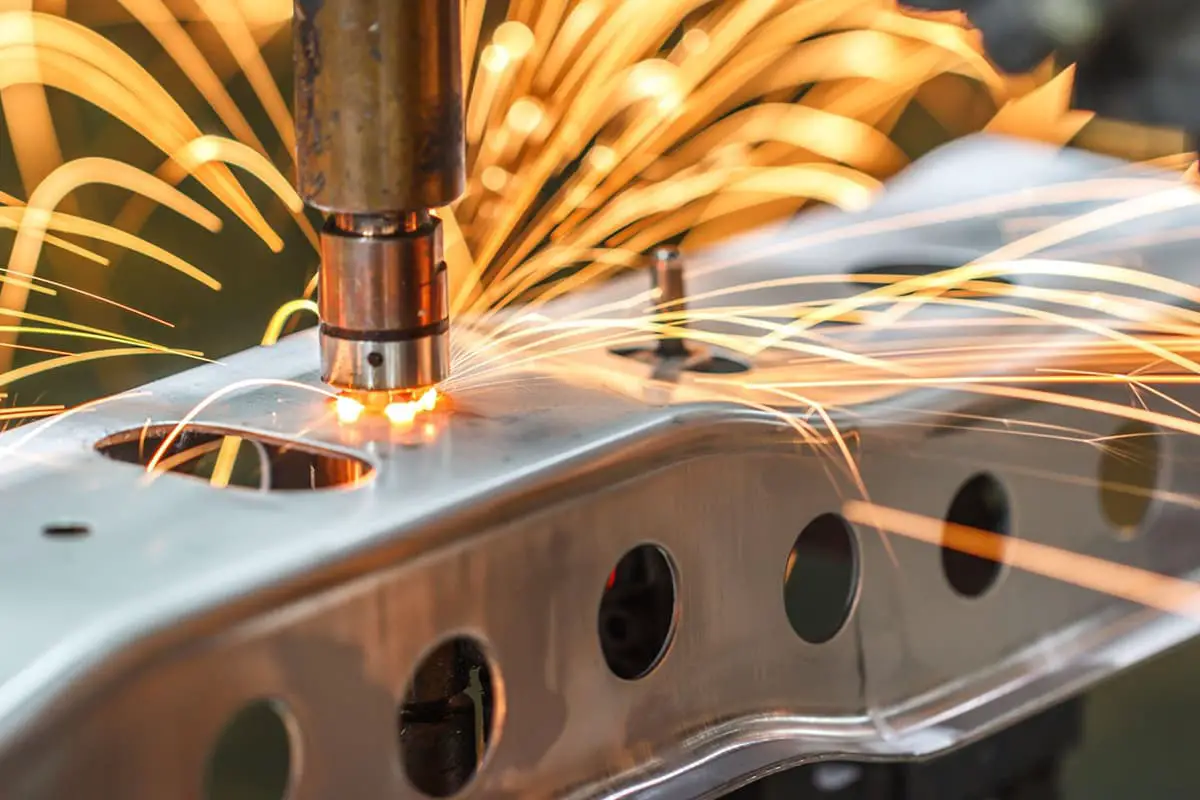
In recent years, the development of laser technology in the field of material processing has been particularly impressive, with applications such as laser marking, cutting, drilling, and welding. Among these, laser welding has become especially popular, as it has several unique advantages over traditional welding methods, such as argon arc welding and resistance welding.
The benefits of laser welding include a small thermal influence range, the ability to produce welds with large aspect ratios, high welding strength, and joint strength that can reach or exceed the strength of the base material. Additionally, laser beams can be easily transmitted through high-energy optical fibers, making it possible to automate the welding process.
Laser welding typically employs CO2 lasers, disc lasers, Nd: YAG lasers, fiber lasers, and semiconductor lasers. Among these, fiber lasers are a relatively new development in laser technology, with a high photoelectric conversion efficiency of 30% and a compact size. They have low maintenance requirements, a long lifespan, and are commonly used for welding stainless steel and aluminum alloys.
Quasi-continuous pulse fiber lasers are a new type of laser source developed by the American company IPG in recent years. They offer high peak power and pulse widths up to the millisecond level, making them well-suited for metal welding and other material processing. Although they are widely used for electronic precision welding, there is limited research on the detailed welding process.
In this study, the focus, which is a critical factor in the welding process, is used as a starting point to investigate the difference in laser beam quality under different focus conditions and its impact on the welding effect.
This article utilizes a 150W quasi-continuous pulse fiber laser as the welding light source. The technical specifications of the laser can be found in Table 1.
Table 1 Laser technical parameters
| Average power /W | 150 |
|---|---|
| Peak power /W | 500 |
| Pulse width /ms | 0.2-20 |
| Frequency/ Hz | 0-2500 |
| Cooling method | Air cooling |
| Beam quality BPP/mm*mrad | 1-2 |
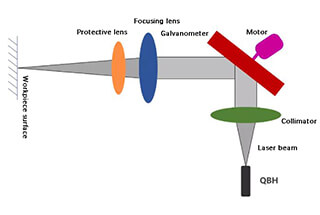
The laser processing head is moved relative to the workpiece through the operation of the X/Y/Z mobile platform to perform the welding of the track. The laser processing head and the laser output signal are connected through a motion control board, meaning that after being positioned at a specific location, the laser emits light for welding.
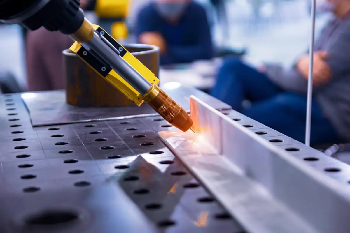
In this article, 304 stainless steel is used as the test material, with a lap welding method applied. The thickness of the upper material is 0.2mm, the thickness of the lower material is 0.5mm, and the dimensions of the material are 100mm x 50mm.
Before welding, the surface of the material is cleaned with acetone and alcohol to remove any impurities such as oil stains. A self-made fixture is utilized to compress the upper and lower layers of material, reducing any gap between the two layers and ensuring the accuracy and dependability of the welding test results.
The main factors that have an impact on the outcome of laser welding are the laser peak power, pulse width, and defocus (the distance between the laser focus and the workpiece surface), with defocus being a particularly crucial factor.
Defocus is defined as positive when the focus is above the surface of the workpiece, and negative when it is below the surface.
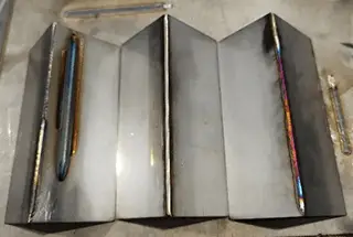
The most reliable method for determining the position of the laser focus is the triangle stainless steel laser calibration method. This method involves using a low-energy laser (50W) to make a spot on the stainless steel, with the strongest spark indicating the location of the laser focus. A stainless steel triangle block is then placed near the laser focus, and a laser beam is used to draw a line on the block, spaced approximately 2mm apart from 0.5mm. The narrowest line width is measured using a microscope, and this measurement represents the laser focus.
The quality of the laser beam is tested using a beam analyzer, laser probe, and laser attenuator. The laser probe is first placed at the laser focus for testing, and then the laser processing head is lifted upward by 1mm at a time, with defocus set at 0mm, 1mm, 2mm, 3mm, and 4mm.
The results of the test, showing the beam distribution, are presented in Figure 1.
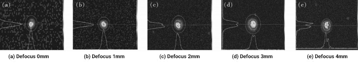
Figure 1 Changes in beam quality with defocus
When the defocus is set at 0mm, the laser energy is primarily concentrated in the center of the spot. As the defocus increases, the distribution of laser energy across the spot becomes increasingly uniform. At a defocus of 3mm, the distribution of laser energy across the spot is the most balanced. However, when the defocus is increased to 4mm, the distribution of laser energy becomes uneven.
The workpiece is positioned at the laser focus, and the laser peak power and pulse width are set. A spot is then made on the stainless steel sample by gradually increasing the power and pulse width until clear traces are visible on the back of the underlying material. In this instance, the laser peak power was 500W and the pulse width was 3ms.
With the peak power, pulse width, and other parameters unchanged, the defocus amount was adjusted by 1mm at a time, and the appearance of the solder joint was recorded. These results can be seen in Figure 2.
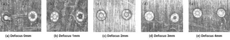
Figure 2 The appearance of solder joints changes with the amount of defocus
The results showed that when the defocus was set between 0mm and 1mm, the solder joint was the smallest and had welding spatter. This is likely because, at this defocus range, the laser energy was primarily concentrated in the center of the spot, resulting in a high density of laser power at the center of the solder joint, causing spatter.
As the defocus continued to increase, the solder joints became more uniform and free of spatter, likely due to the more uniform distribution of the laser beam. However, when the defocus was greater than 4mm, the roundness of the solder joint became inconsistent and the size of the solder joint was reduced to some extent, possibly due to the uneven distribution of laser energy on the spot.
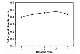
The results also showed that as the defocus increased from 0mm to 3mm, the size of the solder joint gradually increased, with the diameter of the solder joint growing from 0.4mm to 0.5mm. This is because as the defocus increased, the laser spot on the material surface grew larger, leading to larger solder joints.
However, when the defocus was increased to 4mm, the size of the solder joints decreased instead. This may be due to the changed distribution of the laser beam, with low energy at the edge of the spot where the laser was in contact with the material, resulting in a larger spot on the surface but a smaller solder joint.
The relationship between the diameter of the solder joint and the amount of defocus is shown in Figure 3.
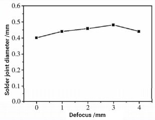
Figure 3 Relationship between solder joint diameter and defocus
A slicer was used to cut along the edge of the laser solder joint. After undergoing rough grinding, fine grinding, and polishing, the center of the solder joint was observed during polishing. Finally, after undergoing corrosion treatment with a nitric acid and alcohol solution, the change in solder joint penetration under different defocus conditions was tested.
The results showed that when the defocus was set between 0mm and 1mm, the solder joint had the deepest penetration and reached into the underlying material. When the defocus was set between 2mm and 3mm, the weld penetration became shallower and only penetrated 1/2 of the thickness of the underlying material. However, when the defocus was set at 4mm, the weld penetration depth was significantly reduced and only penetrated 1/3 of the thickness of the underlying material, as shown in Figure 4.
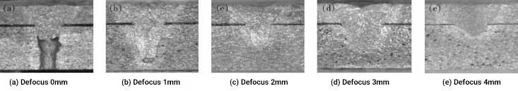
Figure 4 Change of solder joint penetration with defocus
A tensile machine was used to test the strength of a single solder joint by fixing the lower material and pulling the upper material upward. To ensure accurate tensile test data, 3 samples were tested for each set of parameters, and the average value was taken.
The defocus amount was set at 0mm, 1mm, 2mm, 3mm, and 4mm, corresponding to solder joints with strengths of 7N, 8N, 11N, 15N, and 6N, respectively.
As a general trend, the tensile strength of the solder joints increased as the defocus increased. This was because, as the defocus increased, the size of the solder joints also increased, particularly the width of the contact between the upper and lower material, leading to an increase in tensile strength. However, when the defocus was increased to 4mm, the tensile strength decreased, likely due to the worsening of the beam quality and the larger spot size, which led to a decrease in the laser power density and thus the penetration depth and strength of the solder joint.
Based on the experimental data, the tensile strength of a single solder joint reached its maximum value of 15N when the defocus was set at 3mm.
This article investigated the laser beam distribution under different defocus conditions and found that as the defocus increased, the distribution of laser energy on the spot became more uniform, but when the defocus exceeded 4mm, the energy distribution became uneven.
Through testing the stainless steel lap welding process, the study concluded that under constant other factors, adjusting the defocus amount affected the appearance, size, penetration, and tensile strength of the solder joint, and overall appearance and strength requirements.
The conclusions were:

As the founder of MachineMFG, I have dedicated over a decade of my career to the metalworking industry. My extensive experience has allowed me to become an expert in the fields of sheet metal fabrication, machining, mechanical engineering, and machine tools for metals. I am constantly thinking, reading, and writing about these subjects, constantly striving to stay at the forefront of my field. Let my knowledge and expertise be an asset to your business.