1. Introduction
What is Press Brake Crowning?
The CNC sheet metal bending machine is a crucial piece of equipment in sheet metal processing, as its working accuracy directly affects the accuracy of the final bend.
During the bending process, the maximum force at both ends of the ram results in a reaction force on the plate that causes a concave deformation on the bottom surface of the ram. This deformation is largest in the middle part of the ram.
To eliminate the negative impact of ram deformation, it is necessary to compensate for the deflection. This is achieved through hydraulic or mechanical crowning, which causes an upward elastic deformation in the middle part of the worktable, offsetting the deformation of the ram and ensuring the accuracy of the machining joint surface.
Currently, most press brake manufacturers around the world use mechanical compensation devices, such as Bystronic. In China, some press brake manufacturers use mechanical compensation, like Shanghai ACL and YSD, while others use hydraulic compensation, such as Yangli, JFY, and Yawei.
2. Working principle
This article will explain the working principles of hydraulic compensation and mechanical compensation using the Netherlands DELEM DA6x series CNC system as an example, as there are many types of CNC press brake control systems.
2.1 Working principle of hydraulic compensation
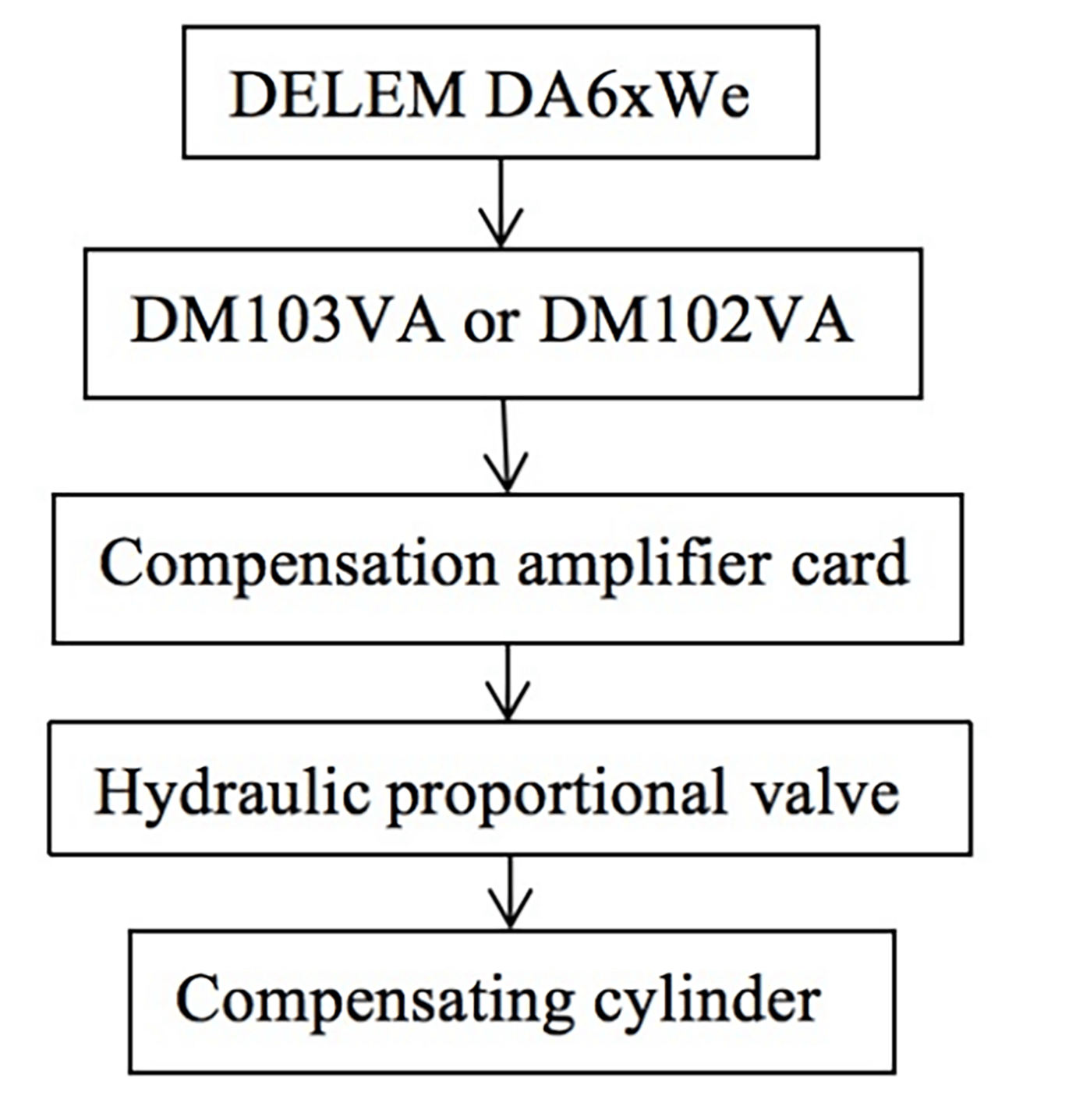
Figure 1 illustrates the control schematic diagram of the compensation system with the DELEM DA6x CNC system and HO-ERBIGER hydraulic system.
Fig. 1 Block diagram of the control principle
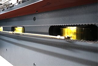
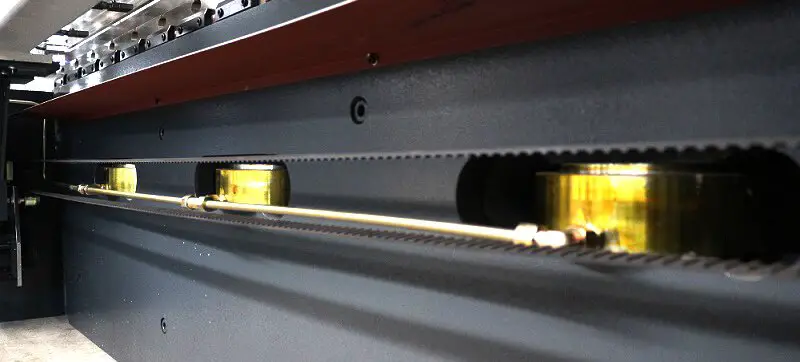
Figure 2(a) shows that the hydraulic proportional valve table consists of three iron plates, with one thick plate and two relatively thin side plates. In Figure 2(b), where the compensation cylinder is located, the middle main board is noticeably more prominent.
When bending the workpiece, the CNC system automatically calculates the compensation value and opens the proportional valve, allowing hydraulic oil to fill the compensation cylinder. The piston in the compensation cylinder then causes a small upward elastic deformation in the middle main board, improving the accuracy of the workpiece.
It is worth noting that the accuracy of the workpiece is also dependent on the proper setting of internal parameters within the CNC system.
Fig. 2 Installation of compensation cylinder
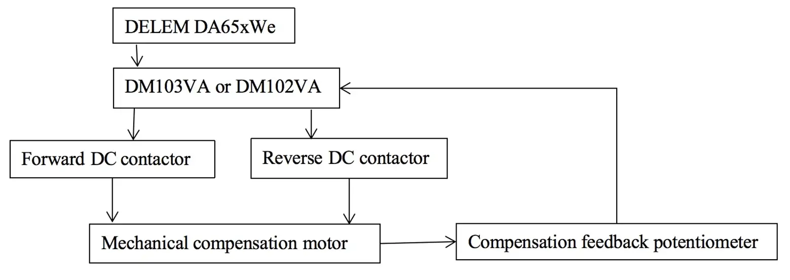
2.2 Working principle of mechanical compensation (Fig. 3)
Fig. 3 Block diagram of the mechanical compensation principle
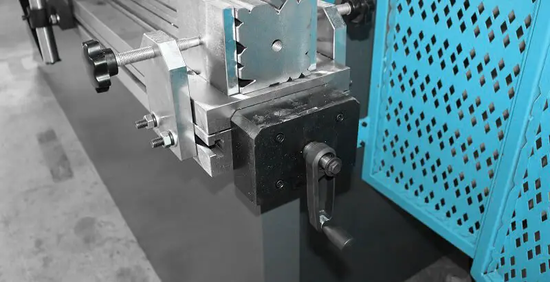
The mechanical compensation mechanism is made up of an upper and lower base plate, as well as a working table, which are connected by disc springs and bolts. The upper and lower base plates are composed of multiple wedges with varying slopes, as shown in Figure 4.
Fig. 4 Base plate
As shown in Figure 4, there is a noticeable difference in slope between the two ends and the middle of the upper and lower base plates, as the middle part of the press brake requires the greatest amount of compensation for deformation.
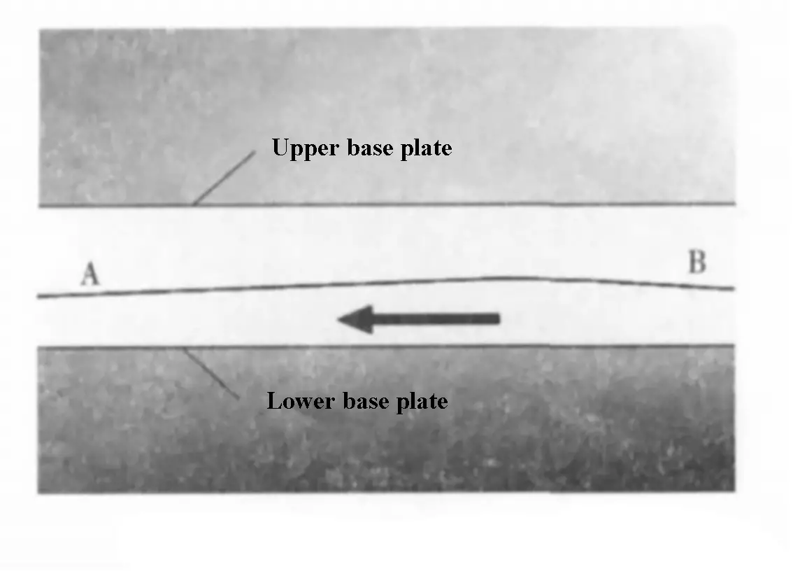
As seen in Figure 5, the slopes of the upper and lower base plates at points A and B are the same.
Fig. 5 Location diagram of upper and lower base plates before compensation
Before compensation, the upper and lower base plates fit together tightly.
During compensation, the lower base plate moves in the direction shown in Figure 5, driven by the motor. The upper and lower base plates remain attached at point A and become separated at point B, as seen in Figure 6.
Fig. 6 Location diagram of upper and lower base plates after compensation
Due to the varying slopes of the upper and lower base plates, the upper base plate will undergo upward convex elastic deformation under the influence of the lower base plate.
This type of mechanical compensation mechanism uses an integral upper and lower base plate, but it is also possible to use split wedges with slopes. A screw rod with threads is used to drive the wedge to move left and right, compensating for the deformation of the press brake’s ram and improving the accuracy of the workpiece’s bend.
The electrical control principle for this split wedge mechanical compensation mechanism is similar to that for the integral upper and lower base plates. Currently, this type of split wedge mechanical compensation mechanism is widely used in large tonnage press brake machines.
3. Performance comparison
Hydraulic compensation mechanism
The CNC system calculates the required compensation amount based on the thickness and length of the bending material and the selected die, and outputs a corresponding analog voltage to the compensation amplifier card. The amplifier card then amplifies the signal and controls the opening size of the hydraulic compensation proportional valve.
During the entire process, from the moment the sliding block enters the slow down state until the ram returns to the top dead center, the compensation proportional valve remains powered on. If the holding time of the ram at the bottom dead center of the press brake machine changes, the accuracy of the bent workpiece may be affected, especially if the actual deformation of the worktable under the press brake is different for shorter or longer holding times.
In addition, if there are impurities in the hydraulic oil, the valve core of the hydraulic proportional valve may become stuck, leading to larger machining accuracy errors. The compensation pressure is separate from the pressure of the entire system, so when the compensation valve is in use, the pressure of the entire system will be partially reduced.
Finally, because hydraulic oil is used for control, oil leakage can occur if the oil pipe breaks, the sealing ring of the compensation cylinder ages or the joint becomes loose, causing pollution.
Mechanical compensation mechanism
When the ram reaches the top dead center position, the CNC system automatically calculates the required compensation amount based on the thickness and length of the bending material and the selected die. The system module then controls the positive or negative direction of the compensation motor to adjust the compensation deformation and receives feedback on the position of the upper and lower base plates through a potentiometer.
Once the compensation motor is adjusted, the compensation deformation will remain unchanged regardless of the holding time when the ram is at the bottom dead center position. This eliminates the need to turn on the compensation mechanism each time the ram enters the slow down position, reducing energy loss in the entire system.
Additionally, there is no hydraulic pipeline, so there is no risk of oil leakage or pollution. The use of an integral worktable also saves on manufacturing costs.
4. Conclusion
After analyzing and comparing the working principles of hydraulic and mechanical compensation, it can be concluded that the latter is superior. As users’ requirements for press brake performance continue to evolve, new demands are placed on press brake manufacturers.
It is expected that more machine tool manufacturers will adopt this new type of mechanical compensation mechanism in response to these changing needs.