How do we ensure precision in sheet metal bending? This article explores key parameters affecting the bending process, such as bending radius and material thickness. By analyzing experimental data and measuring techniques, it highlights common errors and provides solutions for selecting the right tools and methods. Readers will gain insights into improving dimensional accuracy and enhancing the quality of bent metal components.
To enhance the precision of bending elevator sheet metal components, the bending radius (R-angle) of commonly used materials such as SPC, SPHC, SUS304, and 804-GG was accurately measured at a 90° angle using a CNC press brake in the sheet metal workshop. An optical measuring instrument was utilized to determine the bending radius, and the bending coefficient was calculated with the aid of vernier calipers.
The test results serve as a reference and provide data support for selecting appropriate bending tooling, enhancing the accuracy of the R-angle during bending, and improving the accuracy of calculating bending dimensions.
Test Significance
The bending radius (inside R) and bending coefficient are crucial factors that impact the quality of the bending process. The bending radius is associated with the bending tool, material thickness, and performance factors, while the bending coefficient is determined by the material thickness, bending radius, and bending angle. The bending coefficient also affects the unfolded dimensions of the workpiece.
The current formula for calculating the 90° bending factor is α = 1.36t + 0.43R (where t represents the material plate thickness). Some of the common errors in calculating the bending factor include:
The difference between the t value and the actual thickness of the material.
The deviation between the actual bending inside R and the required inside R as indicated in the drawing (inside R is usually taken from the drawing when calculating α).
The use of R gauge measurement (where R gauge values below R3 are 0.25 and above R3 are 0.5) in determining the bending R, which results in lower accuracy.
The influence of the material and bending method on the bending R is not taken into account.
When a workpiece is bent multiple times, the error in the bending coefficient accumulates, leading to poor dimensional accuracy in the finished product.
To address these issues, this experiment measured the actual thickness of several bending materials, utilized an optical measuring instrument to more accurately determine the inside and outside bending radius, calculated the actual bending coefficient of the workpiece, and compared the results with the formula. This will aid in the selection of appropriate bending dies, improve the accuracy of the bending forming R, and expand the accuracy of dimensional calculations.
Test scheme
Test material
The test materials used in the experiment were SPCC, SPHC, SUS304, and 804-GG, which were purchased by our company. The thickness specifications for each material can be found in Table 1.
Table 1 Test materials and thickness (mm)
Thickness t/mm
1.0
1.2
1.5
2.0
2.3
2.5
3.0
3.2
4.5
6.0
SPCC
√
√
√
√
√
√
SPHC
√
√
√
SUS304
√
√
√
√
√
804-GG
√
Test specimen
The size of the samples used in the experiment was 100mm x 100mm and they were produced using laser cutting and blanking. This ensured that the dimensional accuracy of the samples was at a level of 0.1mm.
Test equipment
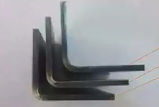
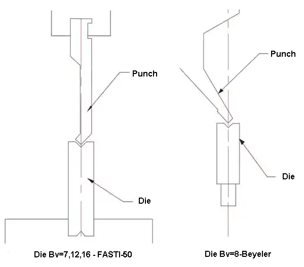
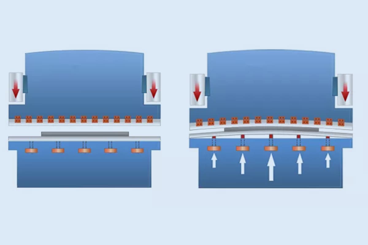
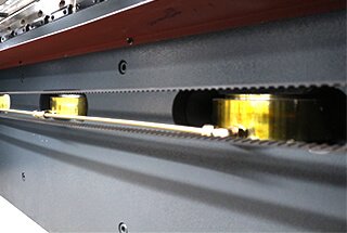
The test bending machine used in the experiment was a CNC press brake located in the elevator production sheet metal workshop. The V-groove used in the experiment featured both FASTI-50 and Beyeler, and the scimitar upper die was selected, as depicted in Figure 1.
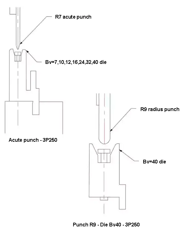
The three-point bending machine used in the experiment was a 3P250. The straight knife upper die selected for the experiment included both the pointed cutter R7 and the round cutter R9, as illustrated in Figure 2.
Fig.2 Three-point bending die
Table 2 The parameters of press brake, punch & die
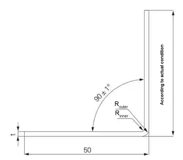
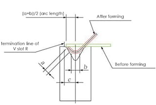
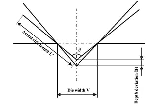
The true thickness of the specimens was measured using a micrometer, and four pieces were averaged for each specific thickness. The specimens were bent using different bending dies at a bending angle of (90 ± 1)°, with the goal of ensuring that one side of the specimens had a length of 50mm, as depicted in Figure 3.
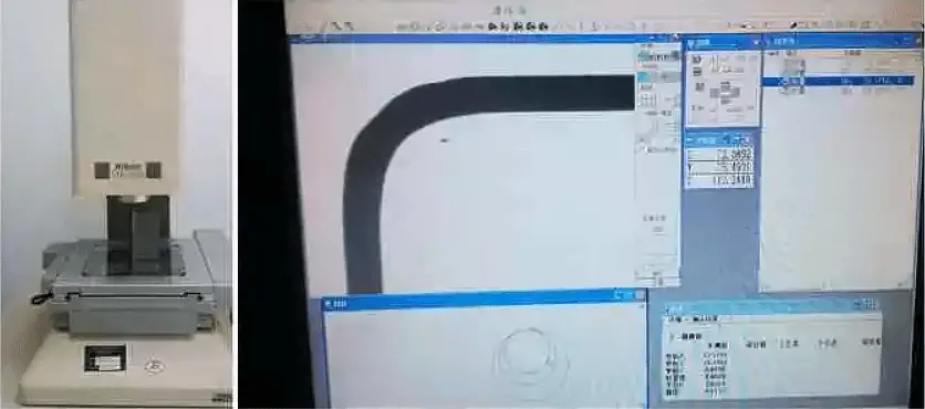
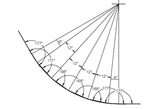
Each thickness specification was repeated 5 times during the bending process. After the bending was finished, the bending angle contours were scanned using an optical measuring instrument to calculate the outer bending angle (R outside) and inner bending angle (R inside), as illustrated in Figure 4.
Fig. 4 Optical measuring instrument and bending R-angle measurement
A vernier caliper was used to measure the length of both sides in order to calculate the bending coefficient. Each thickness specification was repeated 5 times, and the average value was taken.
Test results and analysis
The attached table is a compilation of the test results. The data displayed in the table includes the actual thickness of the test material, the inner and outer radius of the 90° bend, the bending coefficient, and the thinning of the bend.
Actual material thickness
Table 3 compares the actual thickness of the specimen, as measured with a micrometer, with its nominal thickness.
Table 3 The actual thickness of the test materials (mm)
Nominal thickness
1.0
1.2
1.5
2.0
2.3
2.5
3.0
3.2
4.5
6.0
Real thickness
SPCC
1.00
1.18
1.48
2.01
2.50
2.97
SPHC
3.13
4.20
5.91
SUS304 (Remove film)
0.93
804-GG
2.26
The table reveals that the difference between the actual thickness of SPCC and its nominal thickness is within 0.03mm. The actual thickness of the uncoated SUS304 material was found to be about 0.07mm thinner than its nominal thickness. The actual thickness of the 4.5mm hot rolled plate SPHC was measured at 4.2mm.
Bending inside angle Rinner
Comparing the Rinner under different bending conditions, it can be seen that the Rinner is influenced by the material, plate thickness, bending method, and bending tooling.
Of these four factors, the situation of three other factors being equal:
Rinner(SUS304) > Rinner (SPCC).
If the width of the V-groove Bv = 12 mm, the Rinner in SPCC with the thickness of 1.2 mm and SUS304 is 1.85 mm and 2.09 mm, respectively.
When the bending die is the same, for the same material, the plate thickness of Rinnerinfluence is less.
For example, when Bv = 12mm in three-point bending, Rinner in 1.0 ~ 2.0mm thickness of SUS304 is 2.33 ~ 2.51mm, the difference is not significant.
Rinner(three-point) > Rinner (V-groove).
Comparing the same slot width bending lower die (Bv=7mm, 12mm and 16mm) shows that the bending Rinner in three-point is slightly larger than that in V-groove.
The larger the slot width Bv, the larger the Rinner, and the larger the corresponding Rinner
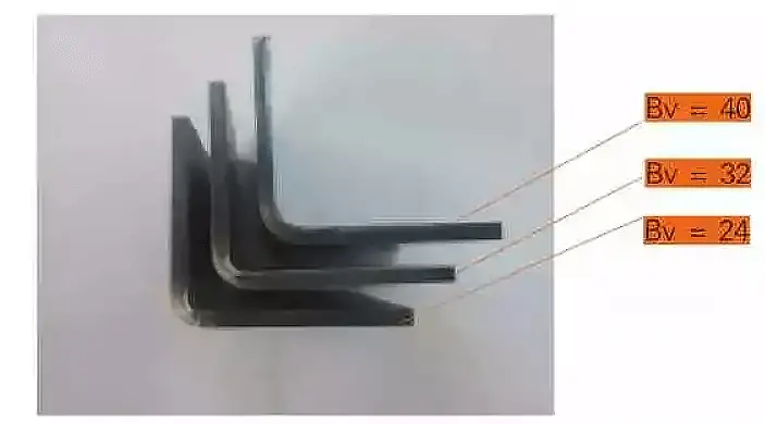
Figure 5 is a comparison of the three-point bending R angles for the lower die slot width Bv is 24mm, 32mm and 40mm, corresponding to about 4.0mm, 4.7mm and 5.9mm of Rinner, respectively.
Fig. 5 Comparison of the inside radius of 4.5 mm SPHC bending with different slot widths (three-point acute punch)
Therefore, in addition to the bending die slot width Bv, the material, bending method (V-slot and three-point) also affects the bending Rinner, which should be paid attention to.
Reducing ratio and outside bending angle Router
In the test, the difference between Router and Rinner is used to represent the average thickness near the bending angle, i.e., t’ = Router – Rinner.
Thus, reducing ratio is η = (t – t’)/t.
From the data in the attached table, it can be seen that thickness reduction occurred in all cases in this test case.
Most of the reducing ratio is within 6%-15%, and the influence of material thickness, bending mode and slot width on the thinning rate is more complicated, and the rule is difficult to identify.
However, it can be seen that the SPHC thinning rate is lower, about 4% to 6%.
The test’s Rinner uses an optical measuring instrument to scanning calculate, while the roundness value can be calculated.
(1) When Bv = 7 ~ 16mm, the roundness value of Rinner and Router is very small, most of which is ≤ 0.05mm, indicating that the bent inner and outer corner contours highly match the degree of roundness.
(2) When Bv = 24mm, 32mm and 40mm (all three-points type), the roundness values of Rinner and Router are slightly increased, exceeding 0.1mm, which means that after the groove width Bv of the lower bending dies increases to 24mm, the degree of arc of the inner and outer contours of the bending decreases.
Bending coefficient α
The schedule also gives the measured and calculated values of the bending coefficient test (currently method used to calculate the bending coefficient, calculation formula: α = 1.36t + 0.43Rinner).
For comparison, the difference is not large (in the calculation, the thickness t and Rinner are both brought into the calculation by the actual test value), which indicates that the current bending coefficient formula α = 1.36t + 0.43Rinner is universal, the bending coefficient depends on two parameters in the actual thickness t of the material and the actual bending Rinner.
The Rinner is influenced by the material, plate thickness, bending method and bending tool, the actual Rinner is the simplest and most effective method.
For new materials or bent parts with other thicknesses, it is necessary to actually measure the true thickness and the bending Rinner of the bending tool.
Conclusion
Based on the above analysis, several conclusions can be obtained:
(1) The test results show the bending Rinner, Router and bending coefficients of several commonly used thickness sheet of SPCC, SPHC, SUS304, 804-GG in the sheet metal workshop CNC press brake machines like Beyeler, FASTI-50 and 3P250;
(2) Rinner is not only related to the bending die but also related to the material;
The test shows that the Rinner of SUS304 is slightly larger than that of SPCC under the same bending parameters;
(3) When the other bending parameters are the same, the Rinner of the three-point bending is slightly larger than the V-groove bending, so the bending work center should be considered when selecting the bending coefficient;
(4) The bending coefficient calculation formula α=1.36t+0.43Rinneris universal.
Accumulating the real thickness of the commonly used bending materials in the workshop and the corresponding bending mold forming Rinner can calculate a more accurate bending coefficient.
As the founder of MachineMFG, I have dedicated over a decade of my career to the metalworking industry. My extensive experience has allowed me to become an expert in the fields of sheet metal fabrication, machining, mechanical engineering, and machine tools for metals. I am constantly thinking, reading, and writing about these subjects, constantly striving to stay at the forefront of my field. Let my knowledge and expertise be an asset to your business.
Ever struggled to get perfect bends in sheet metal? This article dives into essential tips and tricks for mastering sheet metal bending, covering everything from process sequencing to analyzing bendability.…
Struggling with inefficiencies and high costs in sheet metal fabrication? Discover how automated equipment can revolutionize your processes, saving both time and money. This article guides you through selecting the…
Have you ever wondered how massive steel structures on locomotives achieve their precise curves? In this article, we reveal the secrets behind creating large bend radii in sheet metal parts.…
Have you ever wondered how to achieve perfect sheet metal bends? This article dives into essential bending techniques, exploring everything from calculating material expansion to selecting the right tools. You'll…
Ever wondered why your metal bends aren't always perfect? The secret lies in press brake crowning, a technique that ensures precision and quality in metal fabrication. This article will reveal…
1. Introduction At present, the global economy is in a slump and the manufacturing industry has been severely impacted. As a part of the manufacturing industry, the sheet metal industry…
Imagine the precision required to craft complex metal parts with a press brake. Now, picture the frustration when deflections and inaccuracies creep in. This article delves into hydraulic and mechanical…
Why do some folding processes lead to higher losses than others? This article explores how circular pre-folding blades affect the dimensional accuracy of folded sheets. By analyzing various process parameters,…
How does the precision of a press brake impact the quality of metal bending? This article explores the critical link between the manufacturing accuracy of press brakes and the resulting…