Press Brake Operation Manual (Training PDF)
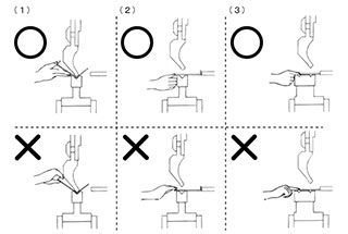
Attention all mechanics and engineering enthusiasts! Have you ever wondered about the ins and outs of operating a press brake machine? In this blog post, we'll dive into the world…
Attention all metalworking enthusiasts! Are you tired of guessing the proper tonnage for your press brake? Look no further! In this blog post, we’ll dive into the world of press brake tonnage calculation, guided by the expertise of a seasoned mechanical engineer. Discover practical formulas, handy charts, and insider tips to master the art of bending sheet metal with precision and efficiency. Get ready to level up your press brake game!
You can use the following press brake tonnage calculator to determine the necessary bending force for your sheet metal bending. The calculator provides both metric and imperial units. I personally recommend using the press brake tonnage calculator below as it is likely the best and most convenient method for calculating the necessary bending force.
The recommended V-opening width for the bottom die
| S | 0.5-3mm | 3-8mm | 9-10mm | >12mm |
| V | 6*S | 8*S | 10*S | 12*S |
For instance, if the sheet metal to be bent is mild steel, with a thickness of 4mm and a bending length of 3.2m, the theoretical width of the bottom die opening should be 8 times the thickness, which is 32mm. Input these figures into the calculator above (remember the units are in mm), and we get a value of 106.12 Ton.
This means you’ll need a minimum bending force of 106 tons to meet your bending needs. Of course, we generally multiply the final result by a safety factor of 1.1, and the resulting value is the press brake tonnage you can choose.
If the width-to-thickness ratio (V/S) is not equal to 9, and the radius-to-width ratio is not equal to 0.16, the above calculator will not be valid.
Please review the updated method for calculating the bending force on a press brake machine.
Use the following bending force calculator instead.
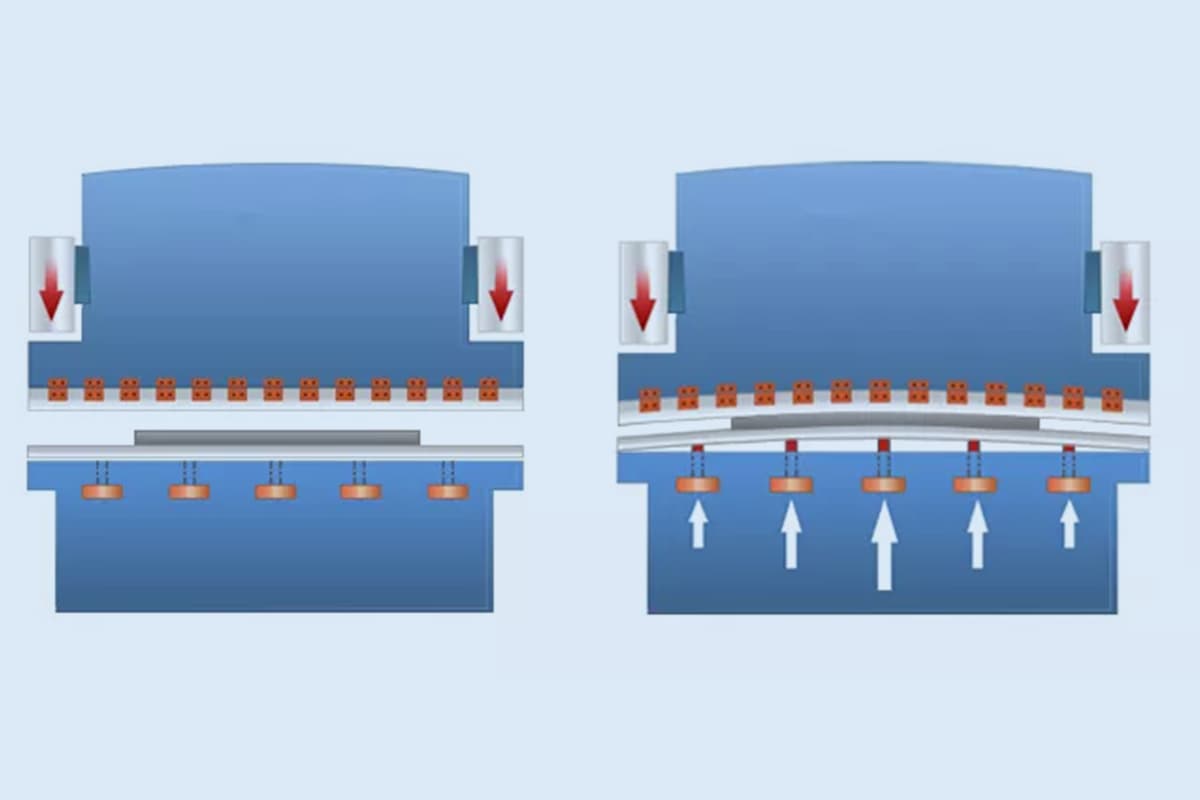
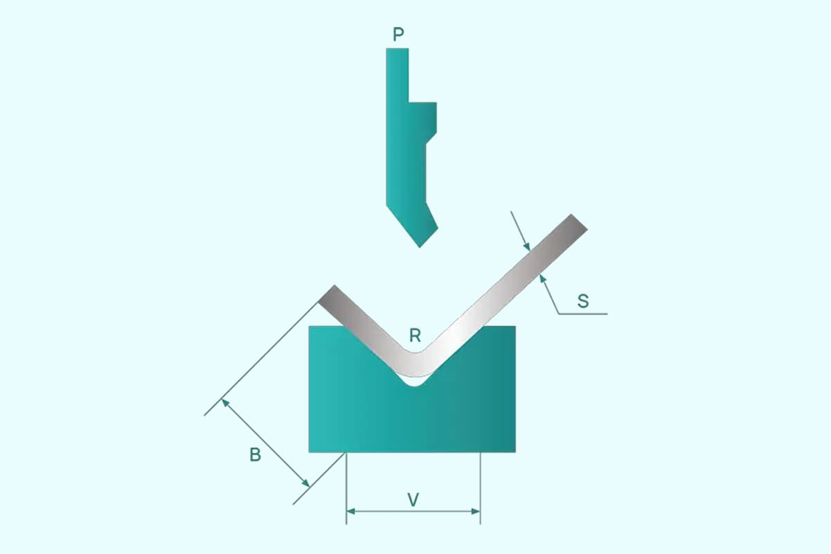
The magnitude of the bending force is influenced by factors such as the size of the workpiece, the mechanical properties of the material, the distance between the fulcrums of the die, the relative bending radius, the clearance between the dies, the friction coefficient between the material and the die, the minimum bending angle, and the bending method.
Consequently, it is difficult to calculate the bending force precisely in theory.
In practice, empirical formulas or simplified theoretical formulas are commonly used for calculation.
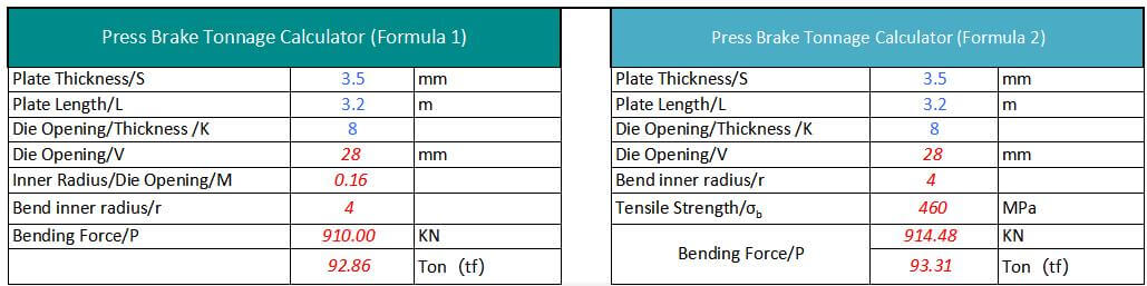
There are currently two main formulas for calculating the tonnage of the press brake that are popular.
The first formula is commonly used in China and the second one in other countries.
However, regardless of which formula is used, the calculated required press brake pressure is basically the same. Let me introduce these two formulas separately below.
where,
For example:
Plate thickness S=4mm, width L=3m, σb=450N/mm²
Generally slot width V=S*8
Therefore P=650*4²*3/4*8=975 (KN) = 99.5 (Ton)
The result obtained using the bending force formula is very similar to the data in the bending force chart.
Note that method #1 to calculate the press brake tonnage is based on mild steel material.
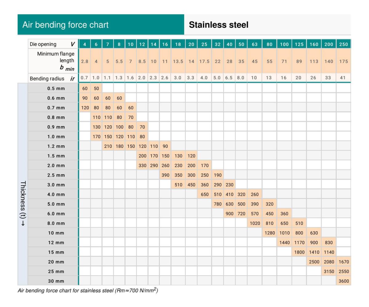
If the material is stainless steel, aluminum, or brass, you can easily adjust the calculation results by multiplying them with the coefficients listed in the following table.
| Material | Coefficients |
| Mild Steel | 1 |
| Stainless Steel | 1.6 |
| Aluminum | 0.65 |
| Brass | 0.5 |
For example:
Plate thickness S=4mm, width L=3m, σb=450N/mm²
Generally slot width V=S*8
Therefore P=1.42*450*4²*3/48=958.5 (KN) = 96 (Ton)
The key to bending sheet metal with different materials is to determine the tensile strength of that specific material, then calculate the required bending force using the above formula.
The tensile strength table below can be the reference:
| Material | Soft (N/mm²) | Hard (N/mm²) |
|---|---|---|
| Lead | 25 – 40 | – |
| Tin | 40 – 50 | – |
| Aluminum | 93 | 1710 |
| Aluminum Alloy Type 4 | 230 | 480 |
| Duralumin | 260 | 480 |
| Zinc | 150 | 250 |
| Copper | 220 – 280 | 300 – 400 |
| Brass (70:30) | 330 | 530 |
| Brass (60:40) | 380 | 490 |
| Phosphor Bronze / Bronze | 400 – 500 | 500 – 750 |
| Nickel Silver | 350 – 450 | 550 – 700 |
| Cold Rolled Iron | 320 – 380 | – |
| Steel .1% Carbon | 320 | 400 |
| Steel .2% Carbon | 400 | 500 |
| Steel .3% Carbon | 450 | 600 |
| Steel .4% Carbon | 560 | 720 |
| Steel .6% Carbon | 720 | 900 |
| Steel .8% Carbon | 900 | 1100 |
| Steel 1.0% Carbon | 1000 | 1300 |
| Silicon Steel | 550 | 650 |
| Stainless Steel | 650 – 700 | – |
| Nickel | 440 – 500 | 570 – 630 |
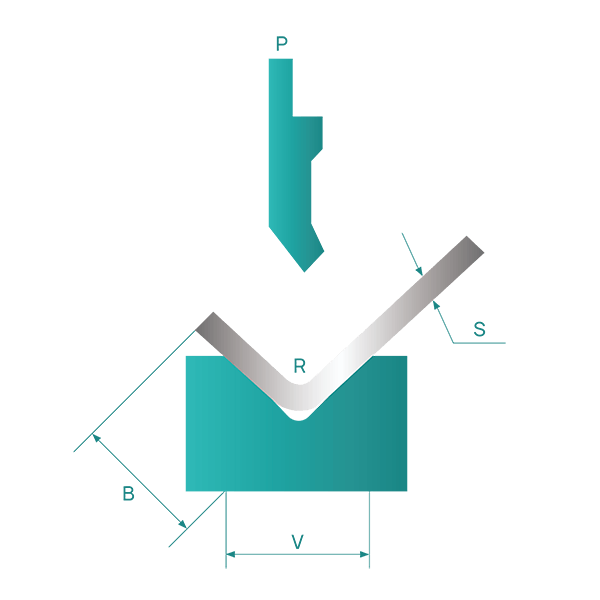
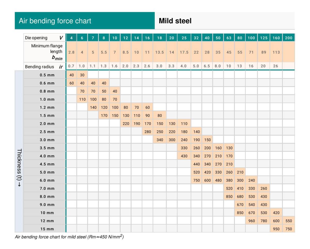
In air bending, the opening width V of the lower die is typically chosen to be 8 to 10 times the thickness of the sheet, S.
Press brake manufacturers often list the corresponding values of the die width, V, and the inner diameter, r, of the bending workpiece on their bending force parameter table.
As a general rule,
r=(0.16~0.17)V
However, when the inner radius is not equal to (0.16-0.17)V, the above calculation formula is no longer applicable.
In these cases, you must refer to a new calculation method to determine the required bending force or press brake tonnage.
The following is the calculator:
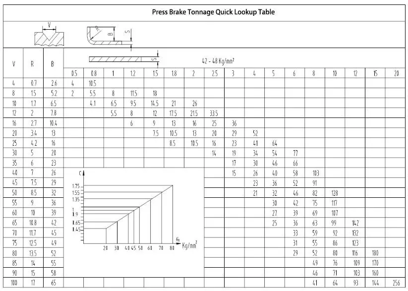
The press brake tonnage chart below can assist you in determining the necessary bending force with ease.
For instructions on how to read a press brake tonnag chart, please refer to this post.
See also:
Data of V, R, B
How to Read Press Brake Tonnage Charts?
The tonnage indicated in the press brake tonnage chart is based on a sheet metal with a tensile strength of σb=450N/mm² and a length of L=1m.
Now that you have the bending force chart, the next step is to understand how to locate the press brake tonnage in the chart.
Assuming your metal sheet has a thickness of 4mm, the general rule is that the V-opening of the bottom die should be 8 times the sheet’s thickness.
However, when dealing with thicker plates, a larger V-opening is necessary.
The recommended V-openings listed below can serve as a reference:
| S | 0.5-3mm | 3-8mm | 9-10mm | >12mm |
| V | 6*S | 8*S | 10*S | 12*S |
Let’s consider a metal sheet with a thickness of 4mm.
Typically, the vee opening of the bottom die should be 8 times the thickness of the sheet. However, for thicker plates, the vee opening should be larger.
To determine the required press brake tonnage, we need to refer to the press brake tonnage chart.
First, find the row with a thickness value of “4” and then determine the corresponding vee opening value of 32 (4 * 8).
The intersection of the row and column where the “4” and “32” values meet indicates a tonnage of 330 KN.
If we need to bend a 4mm sheet that is 3 meters long, the required tonnage would be 330 * 3 = 990 KN, or approximately 101 tons. In this case, we recommend choosing a press brake with a tonnage of at least 100 tons.
However, it is better to opt for a larger tonnage, such as 120 tons, as the service life of the machine will be longer if it operates at full load for extended periods of time.
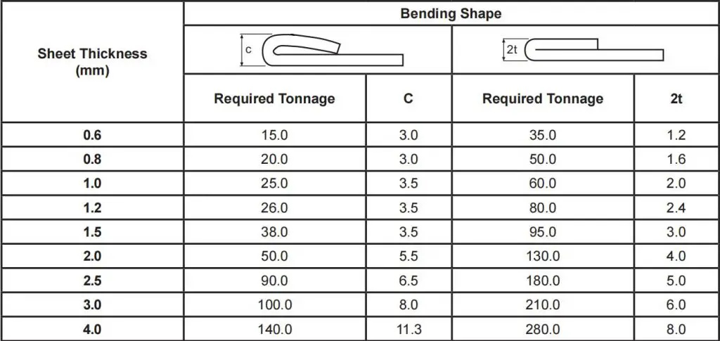
Hemming is a type of bending that requires a higher amount of tonnage compared to standard air bending.
The following tables illustrate the tonnage needed for hemming and seaming operations.
(1) Hemming & Seaming Tonnage Chart For Mild Steel
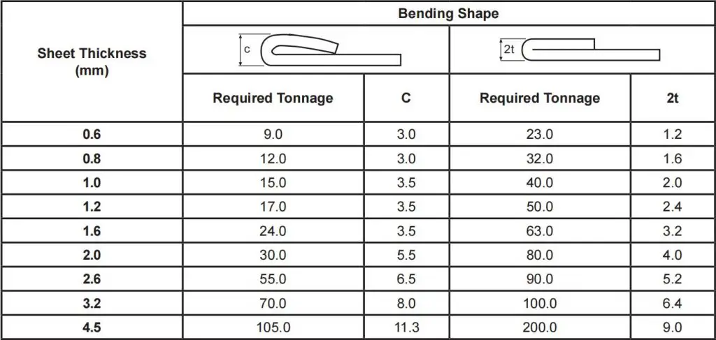
Note: Required tonnage is given per 1-meter length
(2) Hemming & Seaming Tonnage Chart For Stainless Steel
Note: Required tonnage is given per 1-meter length
During sheet metal bending, a bending radius is required at the bending point, which should not be too large or too small, but should be selected appropriately. If the bending radius is too small, it is easy to cause cracking at the bend point, while if the bending radius is too large, the bending may rebound.
The optimal bending radius (inner bending radius) for various materials of different thicknesses is shown in the table below.
Minimum bending radius value (mm)
| Material Science | Annealing state | Cold work hardening state | ||
| Corresponding position between bending curve direction and fiber direction | ||||
| vertical | parallel | vertical | parallel | |
| 08, 10 | 0.1t | 0.4t | 0.4t | 0.8t |
| 15, 20 | 0.1t | 0.5t | 0.5t | 1.0t |
| 25, 30 | 0.2t | 0.6t | 0.6t | 1.2t |
| 4550 | 0.5t | 1.0t | 1.0t | 1.7t |
| 65Mn | 1.0t | 2.0t | 2.0t | 3.0t |
| Aluminum | 0.1t | 0.35t | 0.5t | 1.0t |
| Copper | 0.1t | 0.35t | 1.0t | 2.0t |
| Soft brass | 0.1t | 0.35t | 0.35t | 0.8t |
| Semi hard brass | 0.1t | 0.35t | 0.5t | 1.2t |
| Phosphorus bronze | / | / | 1.0t | 3.0t |
The data in the table above are optimal and for reference only. In fact, the rounding of the bending blade of the manufacturer is usually 0.3, with a few bending blades having a rounding of 0.5.
For ordinary low carbon steel plates, rustproof aluminum plates, brass plates, copper plates, etc., an inner rounding of 0.2 is generally sufficient. However, for some high carbon steel, hard aluminum, and super hard aluminum, this type of bending rounding can lead to bending fractures or cracking of the outer rounding.
Sheet metal bending parts require a bending radius r at the bend. Typically, the blueprints for sheet metal parts have clear markings for the bending radius. The final size after bending is determined by the punch radius r0 and the amount of springback △r, i.e.,
r = r0 + △r.
In actual production, the punch radius r0 used is predominantly between 0.3 and 0.5mm, which can be considered a constant and has a minor impact on the bending radius, thus it can often be disregarded. This means that the bending radius r is closely related to the springback △r.
However, the magnitude of the springback is related to the bending pressure, which in turn is determined by the die slot width B and the sheet thickness t. An increase in the die slot width B reduces bending pressure and increases springback, while a decrease in B increases bending pressure and reduces springback.
Therefore, under certain bending machine conditions, the factors most influencing the bending radius are the punch radius r, die slot width B, and sheet thickness t.
The following formula can be used to calculate the press brake bend radius:
The minimum internal edge is the shortest side that can be bent without the sheet metal slipping into the vee during bending.
In fact, the sheet metal must lie on both sides of the vee while reaching the angle required, otherwise it will slip into the vee with subsequent unsatisfactory results.
The minimum internal edge can be calculated with the following formula:
If the angle required is 90°, minimum internal edge = V x 0.67
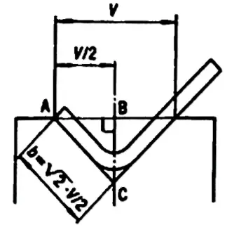
This formula derives from a geometric calculation, since the minimum internal edge is the diagonal of a square with side=V/2. Then by taking the radius into consideration, the result is approximated to V x 0.67.
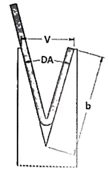
Where the angle required is other than 90°, the minimum internal edge will also be different, as the shortest side that can lie on the vee depends on the angle.
In fact, if a profile has an acute angle, the sheet metal will be pushed further into the die vee and therefore, the side has to be longer.
On the other hand, if a profile has an obtuse angle, it requires a shorter side to lie on a die. For this reason, correction factors must be used to calculate the proper minimum internal edge.
| Angle | Correction Factors |
| 30° | B = (V x 0.67) x 1.6 |
| 60° | B = (V x 0.67) x 1.1 |
| 90° | B = (V x0.67) x 1.0 |
| 120° | B = (V x 0.67) x 0.9 |
| 150° | B = (Vx 0.67) x 0.7 |
The calculation formula for the minimum bending edge is different for different bending angles, which can be found in the table below.
| 165° | 135° | 120° | 90° | 60° | 45° | 30° |
| 0.51×V | 0.55×V | 0.58×V | 0.71×V | 1×V | 1.31×V | 1.94×V |
L-bending
Reference table for inner bending radius R and minimum bending height of cold-rolled thin steel plate materials:
| Serial number | Material thickness | Width of concave groove | Punch R | Minimum bending height |
| 1 | 0.5 | 4 | 0.2 | 3 |
| 2 | 0.6 | 4 | 0.2 | 3.2 |
| 3 | 0.8 | 5 | 0.8/0.2 | 3.7 |
| 4 | 1.0 | 6 | 1/0.2 | 4.4 |
| 5 | 1.2 | 8 (or 6) | 1/0.2 | 5.5/4.5 |
| 6 | 1.5 | 10 (or 8) | 1/0.2 | 6.8/5.8 |
| 7 | 2.0 | 12 | 1.5/0.5 | 8.3 |
| 8 | 2.5 | 16(14) | 1.5/0.5 | 10.7/9.7 |
| 9 | 3.0 | 18 | 2/0.5 | 12.1 |
| 10 | 3.5 | 20 | 2 | 13.5 |
| 11 | 4.0 | 25 | 3 | 16.5 |
Z-bending
The minimum bending dimension L for Z-bending of sheet metal with different thicknesses is shown in the table below:
Minimum height of z-bend:
| Serial number | Material thickness | Width of concave groove | Punch R | Z-bend height L |
| 1 | 0.5 | 4 | 0.2 | 8.5 |
| 2 | 0.6 | 4 | 0.2 | 8.8 |
| 3 | 0.8 | 5 | 0.8/0.2 | 9.5 |
| 4 | 1.0 | 6 | 1/0.2 | 10.4 |
| 5 | 1.2 | 8(6) | 1/0.2 | 11.7(10.7) |
| 6 | 1.5 | 10(8) | 1/0.2 | 13.3(12.3) |
| 7 | 2.0 | 12 | 1.5/0.5 | 14.3 |
| 8 | 2.5 | 16(14) | 1.5/0.5 | 18.2(17.2) |
| 9 | 3.0 | 18 | 2/0.5 | 20.1 |
| 10 | 3.5 | 20 | 2 | 22 |
| 11 | 4.0 | 25 | 3 | 25.5 |

Bending rebound angle:
Δα = b – a
where:
b – Actual angle of the workpiece after the rebound
a – Angle of the die
Size of rebound angle:
The rebound angles for 90° single angle air bending are shown in the table below.
| Material | r/t | Thickness t(mm) | ||
| <0.8 | 0.8~2 | >2 | ||
| Low carbon steel | <1 | 4° | 2° | 0° |
| Brass, σb=350MPa | 1~5 | 5° | 3° | 1° |
| Aluminum, zinc | >5 | 6° | 4° | 2° |
| Medium carbon steel, σb=400-500MPa | <1 | 5° | 2° | 0° |
| Hard brass, σb=350-400MPa | 1~5 | 6° | 3° | 1° |
| Hard copper, σb=350-400MPa | >5 | 8° | 5° | 3° |
| High carbon steel, σb>550Mpa | <1 | 7° | 4° | 2° |
| 1~5 | 9° | 5° | 3° | |
| >5 | 12° | 7° | 6° | |
Factors affecting rebound and measures to reduce rebound:

In choosing the tonnage for a press brake machine, the following factors need special consideration to ensure processing quality:
Thickness and type of material: Firstly, it is crucial to ensure that the bending machine can handle the thickness and type of material being used.
Material and thickness of the metal sheet required for processing: Calculating the necessary tonnage of the press brake machine based on the material and thickness of the metal sheet needed for processing is extremely important.
Bend radius of the workpiece: During the bending process, the bend radius of the workpiece is also a factor to consider. This includes utilizing free bending, where the bend radius is 0.156 times the size of the V-groove opening.
Bending accuracy: Lastly, bending accuracy needs to be considered, that is, choosing between a CNC bending machine or a manual bending machine, as this will directly affect the precision of the parts processed.

As the founder of MachineMFG, I have dedicated over a decade of my career to the metalworking industry. My extensive experience has allowed me to become an expert in the fields of sheet metal fabrication, machining, mechanical engineering, and machine tools for metals. I am constantly thinking, reading, and writing about these subjects, constantly striving to stay at the forefront of my field. Let my knowledge and expertise be an asset to your business.