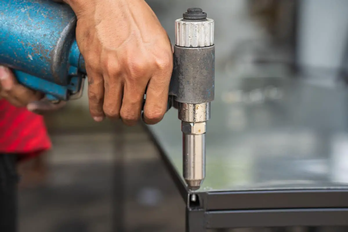
Sheet Metal Joining Process: The Ultimate Guide
Have you ever wondered how sheet metal parts are joined together to create complex structures? In this blog post, we'll explore the fascinating world of sheet metal joining techniques. As…
Ever wondered how intricate shapes and precise bends are created in sheet metal? This article dives into the fascinating world of folding machines, revealing their essential role in bending and forming metal sheets. Discover the key principles, structural components, and varied uses of these machines. Learn how they differ from other bending methods and why they are crucial in both sample and mass production. Prepare to gain a deeper understanding of the techniques and tools that shape the metal parts we use every day.

The folding machine is used for bending and forming various metal sheets such as iron, stainless steel, copper, and aluminum. It can also be used as a press machine to complete die forming, riveting, leveling, and other processes.
Workpieces are cut and fed by LASER or NCT, and other non-folding shape elements are made by machining, and then the bending and forming are done using the folding machine knife or folding machine die.
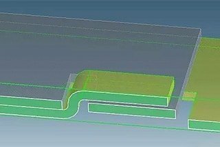
In addition, drawing of convex and concave shapes, pressing of corner pads, and line pressing are also commonly done on folding machines.
With the use of the folding machine knife and die, the folding machine can complete the bending of many types of products, but its processing speed is slower than that of a punching machine.
It is suitable for bending and forming in sample production and certain mass production.
The upper and lower dies are fixed on the upper and lower worktables of the folding machine respectively. The relative movement of the worktables is driven by hydraulic transmission, combined with the shape of the upper and lower dies, to achieve bending and forming of the sheet metal.
The folding machine consists of four parts: 1. Mechanical part 2. Electrical part 3. Hydraulic part 4. NC electrical control part.
(1) Upper motion: The lower worktable does not move, and pressure is applied by the descending upper slider.
(2) Lower motion: The upper machine is fixed and pressure is applied by the rising lower worktable.
Bending from the inside to the outside.
Bending from small to large.
Bending special shapes first, then general shapes.
The previous process does not affect or interfere with the subsequent process.
Drawing of convex and concave shapes, pressing of corner pads, forming of self-tapping threads, line pressing, printing, riveting, riveting of electrostatic conductive rails, pressing of grounding symbols, punching, riveting, flattening, and triangle reinforcement.
1. Upper die:
Also known as the folding knife.
Classification of folding machine upper dies and existing tool types are shown in the figure below:

The upper mold of the folding machine is divided into integral and segmented types.
The integral upper mold has two sizes: 835mm and 415mm.
The segmented upper mold is divided into type A and type B.
The length of type A segments includes 10mm, 15mm, 20mm, 40mm, 50mm, 100mm (right horn), 100mm (left horn), 200mm, and 300mm.
The length of type B segments includes 10mm, 15mm, 20mm, 40mm, 50mm, 100mm (right horn), 100mm (left horn), 165mm, and 300mm.
The following figure shows the 107# folding mold with type A segments.

2. Lower die
Also known as “V-groove”.
The lower die of the folding machine is divided into two types: integral and segmented.
The integral lower die is divided into L and S types (L: 835mm, S: 415mm), while the segmented lower die is divided into 10, 15, 20, 40, 50, 100, 200, and 400 sizes.
The lower die is classified into single V and double V based on the V-groove.

The V-groove is usually referred to as “groove width value + V.” For example, when the V-groove width is 5mm, the V-groove is called “5V.”
The V-groove width of the lower die used in the folding machine is usually 5 times the thickness of the material (5T).
If 5T-1V is used, the bending coefficient should be increased accordingly. If 5T+1V is used, the bending coefficient should be reduced accordingly.
1) Normal back gauge:
The surface alignment is used for end-face alignment of the workpiece and left-right side positioning.
The point alignment is used for two-point or multi-point alignment of the workpiece and can also be used for single-point alignment (with auxiliary facilities).
2) Long double-point back gauge:
Used for the alignment bending of small-width workpieces. Even if the normal back gauges are butted together, there is still a gap of 70mm between the front and back gauges.
This back gauge can reduce the gap to 10mm: avoiding burrs alignment.
It has the same function as a single-point back gauge, but its scope of application is mainly for small width alignment workpieces: the base has both back gauge functions.
3) Short double-point back gauge:
The basic function is the same as the long double-point back gauge, but it is suitable for a different range of workpieces.
It can be used for the alignment of shorter workpieces and is suitable for NCT material cutting workpieces to avoid burr points and ensure bending accuracy.
4) Extended back gauge:
Using the extended feature for indirect alignment of small or negative size workpieces.
This back gauge is long and can extend out of the machine by 59.5 to achieve an alignment size of -59.5.
It can be used for some small bends with high alignment difficulty and for left-right positioning of workpieces.
Because it is longer than the normal back gauge, it can be used as left-right positioning of workpieces when the normal back gauge is used for alignment.
5) Shim back gauge:
Used for small size bending alignment. Generally, the alignment of small size bending requires a shim to prevent the upper die from damaging the back gauge, but when adding a shim, the shim is prone to move and affect safe operation.
The protruding part of this back gauge serves as a shim.
Usage: Install with the protruding part facing down; support the workpiece alignment for large size or reverse alignment.
When bending large size workpieces, generally two people need to reach into the machine and grab the workpiece alignment, which is extremely unsafe and the size is unstable.
This back gauge can support the workpiece alignment and can be operated by one person.
Its base is equivalent to the normal back gauge, so it has the function of a normal back gauge.
6) Single-point back gauge:
Used for long-side alignment of products with multiple burr points, generally for NCT material cutting or edge-cutting products with burr points on the edges.
This back gauge can avoid or pass through burr points to improve bending accuracy. It is also used for left-right positioning of workpieces.
Because its base plane is the same as the normal back gauge, this back gauge can be mixed with the normal back gauge on both sides.
Its protruding part can be used for left-right positioning of workpieces, achieving accurate avoidance between the workpiece and the mold. The base has the function of a normal back gauge.
7) Material inner point alignment back gauge:
Because the protruding point of this back gauge extends out to another plane from the back gauge, it can be used for the alignment of small square holes inside the workpiece.
8)Material inner surface alignment back gauge:
Because it has a protruding structure at the top, the protruding plane is flush with the base plane, and the width is only 1/3 of the base.
It can be used for narrow slit alignment with a width smaller than the normal back gauge width.
When the protruding part is clamped downwards, it can be used for direct alignment of material inner bending.
Its best adaptation range is inner bending width larger than 20mm but smaller than 150mm, and it can also be used for small surface alignment with irregular outer edges.
Note: The general size of its back gauge is 60*9mm.
During bending, the positioning is tightly against the back gauge (parallel to the back gauge).
If the positioning surface of the workpiece is inclined, it should design positioning fixtures based on the size of the workpiece (the stability of the positioning).
Generally, when L≦10mm, it is necessary to consider using positioning fixtures (usually designed as easy molds) to assist in positioning, unless it is a particularly small workpiece.
Of course, the stability of positioning for a workpiece with a 10mm positioning is also poor. See the following figure:

1)Processing range of bending:
The distance from the bending line to the edge should be greater than half of the V-groove.
For example, when using a 4V lower die for a 1.0mm material, the minimum distance is 2mm.
The table below shows the minimum bending edges for different thicknesses of materials.
| Material thickness | Bending angle of 90 degrees | Bending angle of 30 degrees | ||
| minimum bending edge | V-groove specifications | minimum bending edge | V-groove specifications | |
| 0.1~0.4 | 1.0 | 2V | ||
| 0.4~0.6 | 1.5 | 3V | 2.2 | 3V |
| 0.7~0.9 | 2.0 | 4V | 2.5 | 4V |
| 0.9~1.0 | 2.5 | 5V | 3.4 | 6V |
| 1.1~1.2 | 3.0 | 6V | ||
| 1.3~1.4 | 3.5 | 7V | 5.0 | 8V |
| 1.5~1.6 | 4.0 | 8V | ||
| 1.7~2.0 | 5.0 | 10V | ||
| 2.1~2.5 | 6.0 | 12V | ||
| 2.6~3.2 | 8.0 | 16V | ||
| 3.3~5.0 | 12.5 | 25V | ||
| 5.1~6.4 | 16.0 | 32V | ||
Note: If the inner dimension of the bending material is smaller than the minimum bending edge size in the table above, the folding bed cannot be processed in a normal manner.
In this case, the bending edge can be lengthened to the minimum bending edge size, and the edge can be trimmed after bending, or mold processing can be considered.
2) When the folding bed is bending, appropriate processing must be performed due to the small size of the hole edge to the bending line:
(1) LASER processing is performed on the corresponding cutting line of the bending line.
(2) NCT processing is performed on the corresponding pressing line of the bending line (this method is given priority).
(3) Enlarge the hole to the bending line (this method must be confirmed with the customer).
Note: When the distance between the hole near the bending line and the bending line is smaller than the minimum distance listed in the table, deformation will occur after bending.
| sheet metal thickness | 0.6~0.8 | 0.9~1.0 | 1.1~1.2 | 1.3~1.4 | 1.5 | 1.6~2.0 | 2.2~2.4 |
| minimum distance | 2.0 | 2.5 | 3.0 | 3.5 | 4.0 | 5.0 | 5.5 |
3)Reverse folding and flattening:
When the convex bulge is in the opposite direction to the reverse folding and flattening direction, and the distance from the bending line is L ≤ 2.5t, flattening will deform the convex bulge.
Processing method: before flattening, a fixture is placed under the workpiece, and the thickness of the fixture is slightly larger than or equal to the height of the convex bulge. Then use a flattening die to flatten.
4)When the punching hole is too close to the bending line (≦3T+R), it must be processed with a pressing or cutting line at the bending line to prevent deformation of the punching hole during bending.
5)Electroplated workpiece:
Bending of electroplated workpieces must pay attention to pressure marks and peeling of the coating (should be specially indicated on the engineering drawing).
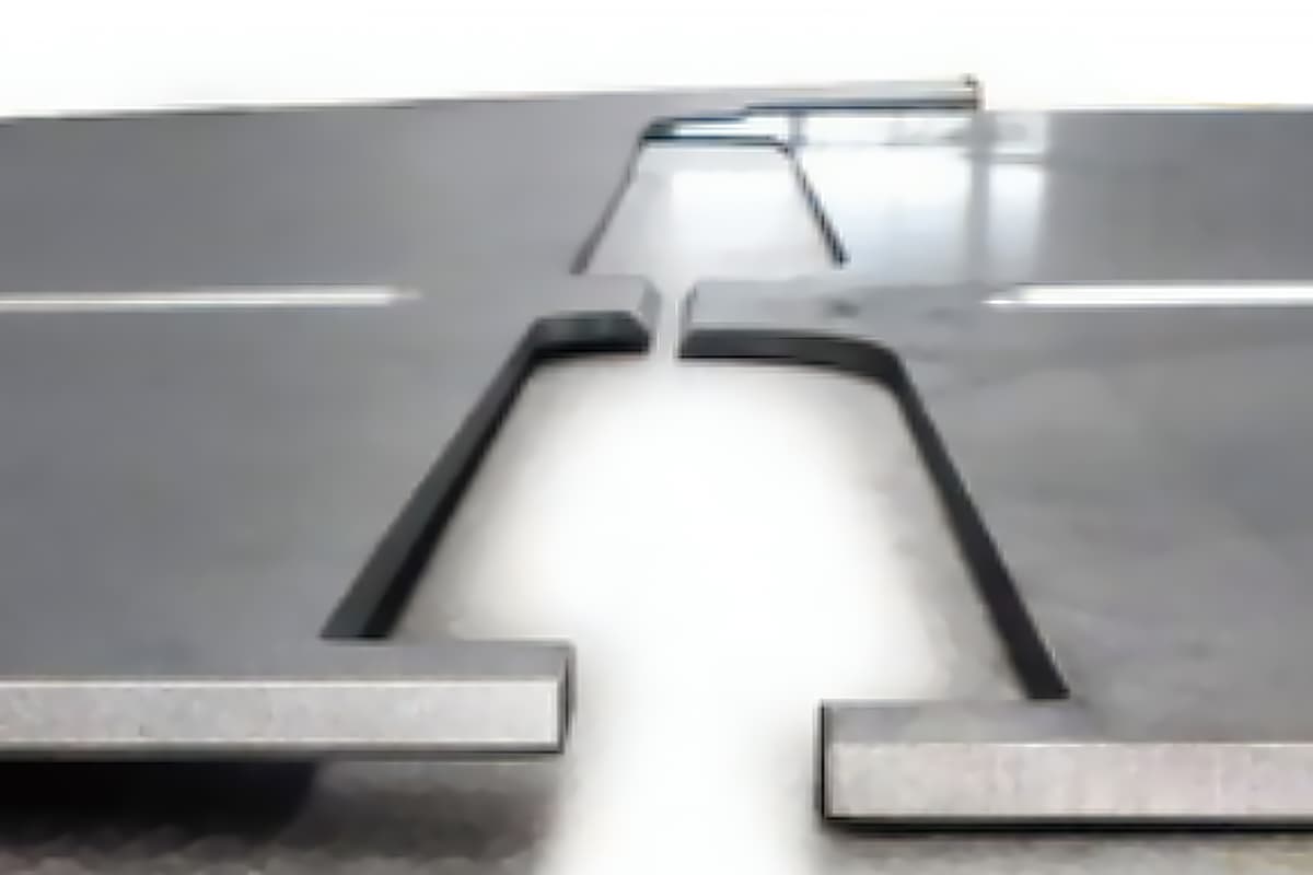
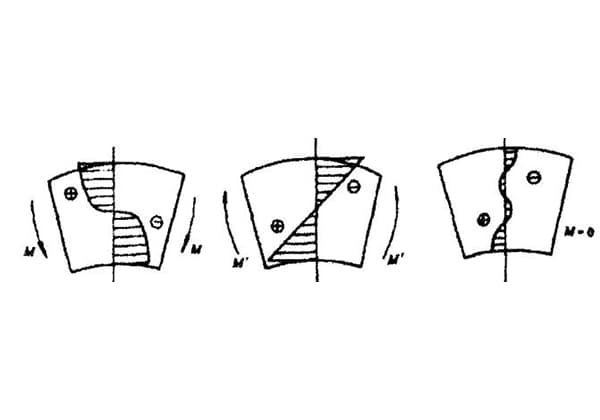
6)Offset
The interference machining range with section deviation can be seen from the diagram.
Based on the forming angle, it can be divided into straight edge deviation and oblique edge deviation, and the processing method depends on the deviation height.
For straight edge deviation: when the deviation height “h” is less than 3.5 times the material thickness, deviation mold or easy mold forming is used.
When it is greater than 3.5 times the material thickness, normal folding with one forward and one reverse is used.
For oblique edge deviation: when the oblique edge length “l” is less than 3.5 times the material thickness, deviation mold or easy mold forming is used.
When it is greater than 3.5 times the material thickness, normal folding with one forward and one reverse is used.

7)Riveting electrostatic guide rail
The spacing between the riveted electrostatic guide rails on the folding machine is 25.15mm, and 15 points can be riveted at once (each riveted punch can be removed, so single and spaced riveting can be performed).
When the distance between the edge of the electrostatic guide rail and the bending line L≧1+V/2mm (where V is the width of the lower mold V-groove of the folding machine), the electrostatic guide rail can be riveted before bending. If it is less than 1+V/2mm, the electrostatic guide rail must be riveted after bending.
For 1.2mm material, it can be folded with a 5V groove, as shown in the diagram.
Note: The width of the electrostatic guide rail is 7.12mm, model: 700-02776-01.
8)Thin and Highly Elastic Materials
When bending angles are extremely important for thin and highly elastic materials, it is recommended to consider using pressure line treatment on the bending line, or to add process holes or strengtheners on the bending line to avoid springback and dimensional errors after bending.
If using easy molding, the amount of springback must be considered when designing the easy mold.
9)Pressing Convex Molding
When pressing convex molds, if high accuracy is required for the height of the convex part, it is recommended to consider using a back-pressure method to ensure its precision.
10)Folding Machine Pressing Triangle Reinforcement
Mold specifications for the triangle reinforcement:
| Knife model number | 117 | 107 | 202 | |||
| Forming width(mm) | 3.0 | 5.0 | 3.0 | 5.0 | 3.0 | 5.0 |
| Tool width(mm) | 10 20 | 10 20 | 10 20 | 10 20 | 10 20 | 10 20 |
| Number of molds | Two each | Two each | Two each | Two each | Four each | Four each |


There are two types of forming for triangular reinforcement:
1. Simultaneously with the bending tool, i.e. bending and triangular reinforcement are processed at the same time.
2. Pressing the triangular reinforcement after bending the workpiece.
Note: The number of triangular reinforcements formed depends on the number of molds.
From the table above, it can be seen that currently the maximum number of triangular reinforcements that can be formed for the same specification is four. If the number exceeds this, it needs to be resolved through consultation with relevant personnel.

As the founder of MachineMFG, I have dedicated over a decade of my career to the metalworking industry. My extensive experience has allowed me to become an expert in the fields of sheet metal fabrication, machining, mechanical engineering, and machine tools for metals. I am constantly thinking, reading, and writing about these subjects, constantly striving to stay at the forefront of my field. Let my knowledge and expertise be an asset to your business.