Ever struggled with creating perfect threads in your workpieces? This article unveils the secrets of tapping, a crucial process in machining. Learn how to enhance tap performance, choose the right tools, and tackle common challenges. Get ready to elevate your tapping skills and achieve flawless results!
Taps are tools used for creating various medium and small internal threads. They have a simple design and are easy to use. They can be operated by hand or on machine tools, making them widely used in production.
Struggling with tapping during the processing process? Don’t worry! Today, I’ll share some tips to help you gain a deeper understanding of tapping.
What is tapping?
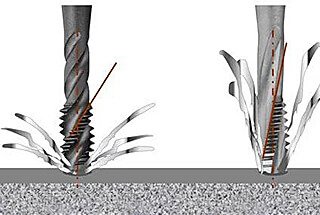
Tapping is the process of cutting an internal thread inside a hole in a workpiece using a tap.
1) Factors that determine tap performance include:
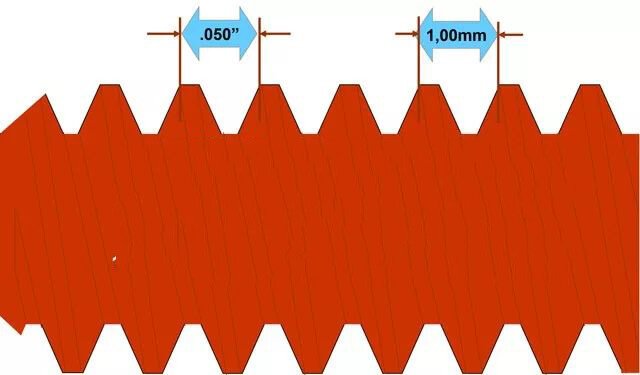
The axial distance between two adjacent teeth on a thread corresponds to two points on the pitch diameter line.
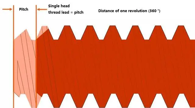
3) Lead:
The axial distance between the corresponding points of two adjacent teeth on the same helix is known as the pitch and is denoted by a code.
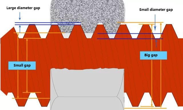
4) Nominal diameter of thread:
The nominal diameter of a pipe thread is the inner diameter of the through pipe (measured in inches), while the nominal diameter of other threads is the major diameter of the thread (measured in metric units).
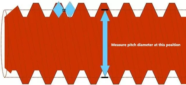
5) Pitch diameter of thread:
The pitch diameter is the most crucial aspect as it determines the fit and strength of all threaded assemblies. It is located on the pitch line, and the width of the tooth at this point is equal to the width of the adjacent tooth slot.
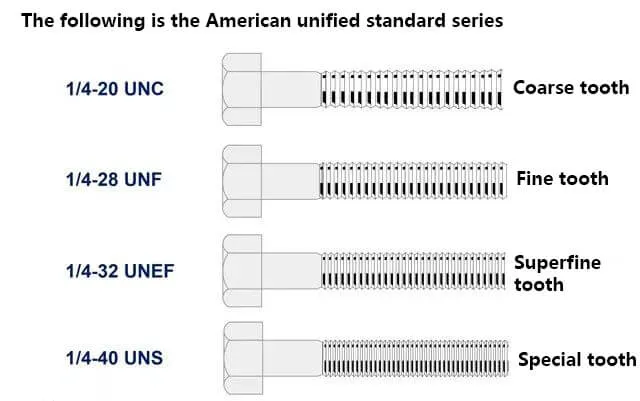
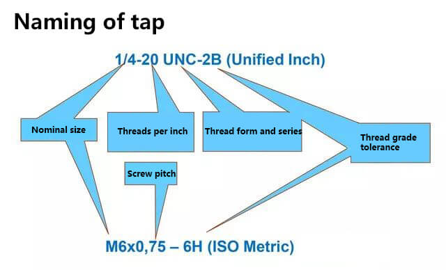
Designation of threads
English thread: The English thread is a type of thread dimension that is marked in the English system. It was developed jointly by the United States, Britain, and Canada to provide a unified system.
Metric thread: The Metric thread is a type of thread developed according to the ISO (International Organization for Standardization) system. It is the global standard for metric threads.
Design high-performance tapping
1) Perfect application
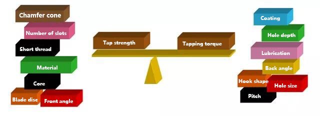
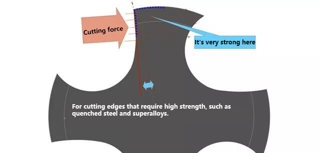
In the tapping process, several factors must be considered, including the design of the workpiece, the design of the tap, and its intended application. The objective is to minimize cutting force and maximize the strength of the tap.
2) Balance options: all aspects of the application must be considered
3) Key points of tap design
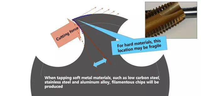
(1) For softer, more viscous materials that produce long chips, the tap should have a simple design, a large front angle and hook angle, a large rear angle, and measures to avoid voids. It should also be designed for easy cutting, with a tendency to collapse at the edges, a fragile overall structure, and a large space for holding chips.
(2) For harder materials, the tap should have a heavy-duty design, a small front angle and hook angle, a small back angle and shovel back, and be able to withstand high cutting pressure. It should also have a strong edge design to reduce edge collapse and have a large cross-section and limited chip holding space.
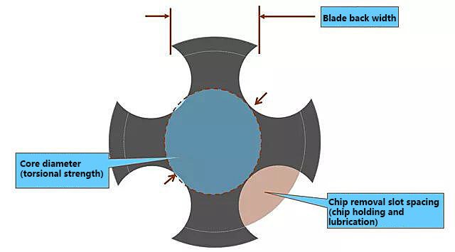
(3) Factors to consider in tap design include the type of tap groove, the material used for the tool, and surface strengthening treatments. These design features must be balanced to ensure proper cutting, chip control, lubrication, and torsional strength.
When cutting, it is important to stop in the middle of the cut and reverse the direction of the hole, while keeping the cutting in the groove. This presents the biggest challenge in tapping and tap design in metal processing.
Shape of tap
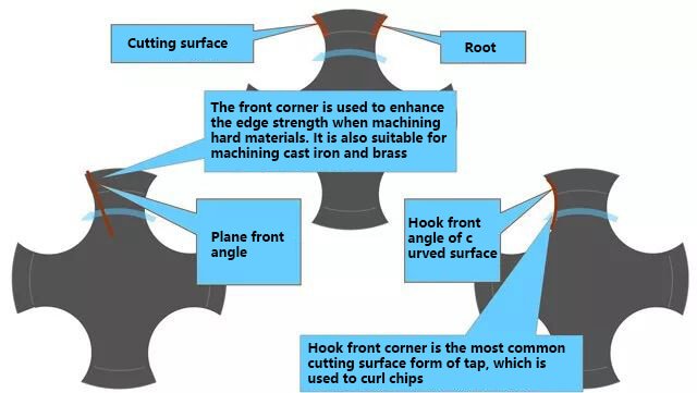
1) Type of tap cutting surface
① Correct selection of positive hook tap
② Correctly select the tap with small or negative hook angle
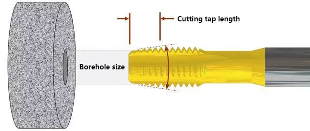
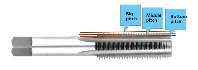
2) Cutting tap
The service life of a tap can be significantly extended with each additional cutting tap tooth. Tests have shown that the tool’s lifespan can be doubled for every half of the cutting tooth thread.
Unlike other tools, the chip load of a tap can only be altered by the number of chip removal slots and the length of the cutting tap.
3) Inverted tap:
Similar to all other tools, the tap is also slightly inverted.
4) Thread shovel back
Advantages of using a thread shovel back include less heat buildup on the tap and less plastic build-up on the back of the workpiece, which can help mitigate the accumulation of chips on the thread.
Disadvantages of using a thread shovel back include the cutting edge becoming brittle and prone to collapse, insufficient rigidity of the main shaft and clamping (including a floating tool handle), and the possibility of small chips becoming embedded during reverse rotation, leading to the collapse of the cutting edge.
5) Tap tolerance
Each tap has its own unique pitch diameter.
Taps marked with H or D tolerance (mainly American taps) indicate the thread size of the tap through the H/D tolerance. The letter indicates whether the tap size is greater than (H = imperial, D = Metric) or lower than (L = imperial, DU = Metric) the basic pitch diameter. The actual tap size is expressed in relation to the basic pitch diameter, such as H2, D3, L1, or DU2.
Taps are also often marked with a thread grade. For example, a general HP tap series indicates that the tap is the correct size for the fitting grade of the part. A grade 3B tap is suitable for a grade 2B part, and a tap marked with an “X” grade indicates that it has a large tolerance and is used for precision taps, electroplated or heat-treated parts, or materials with close to an elastic memory.
For electroplated tapping threads, it’s necessary to select a tap with a larger tolerance grade for internal threads. A larger pitch diameter will result in a slightly larger thread size, and the increase after electroplating will bring the thread size back to the specified value.
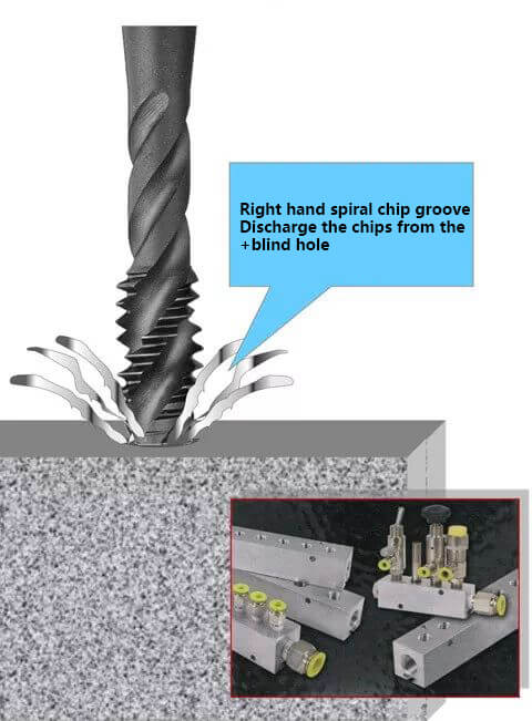
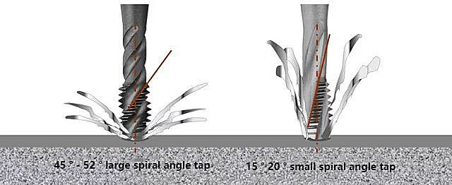
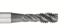
The spiral chip removal slot tap is best suited for blind hole and deep hole processing. It is recommended to use materials that produce sticky chips, making it ideal for intermittent cutting.
The taper core of the spiral chip removal slot tap is very thin, making it the most vulnerable part of the tap design. To avoid breakage, the speed should be 30% to 40% lower compared to that of a straight chip removal slot tap.
3) Pull out cutting
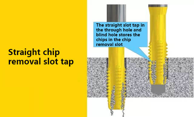
4) Straight chip removal groove tap:
For materials that are prone to breaking chips, such as brass, cast iron, or hardened steel, it is recommended to use a tap with high strength. Coolant or gas is usually needed to flush chips from the chip removal groove.
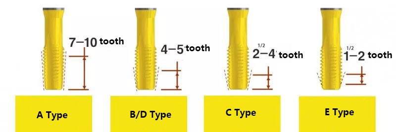
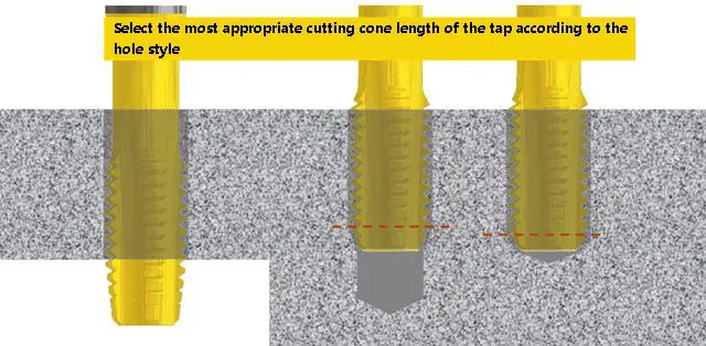
Taps can come in a variety of cutting forms, including:
Taper (Form A) “A” – initial tap
Plug (Forms B & D) “B/D” – middle tap
(Form C) “C” – semi-flat bottom or modified flat bottom
(Form E) “E” – flat bottom
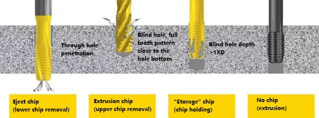
5) Extrusion tap:
Its processing feature is that there is no chip in the through hole or blind hole.
6) Comparison between cutting tap and extrusion tap
7) Influence of bottom hole size on extrusion thread
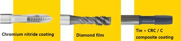
Coating of tap
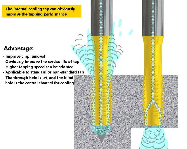
1) Advantages of coating
① Surface Treatment: Improves the appearance of HSS taps without changing their size.
② Improved Tap Life: Offers high wear resistance, reduces friction and power consumption, reduces blade collapse and breakage, and slightly increases surface hardness.
③ Improves Surface Quality and Dimensional Accuracy of Screw Holes: Maintains a sharp cutting edge with a lubricating effect, reduces load and scratches, and minimizes chip buildup.
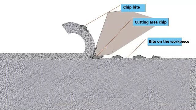
2) What is a chip tumor?
The workpiece material is welded or bitten on the chip edge.
At the start of cutting, a chip buildup forms and grows throughout the cutting process.
When chip buildup becomes severe, the cutting pressure causes it to break apart and the fragments become embedded in the workpiece, leading to a poor finish and deviations from the desired size.
When the chip buildup fragments, the tool material particles break down, leading to tool wear.
3) Traditional surface treatment
Oxidation treatment:
Increase cutting speed by 5% – 10%
Controlled oxidation (rust!)
Black
The porosity of oxidation keeps the cutting fluid on the tool surface
Applicable to ferrous (iron-based) materials, not applicable to titanium, brass, aluminum, composite materials, copper, zinc or plastics
Nitriding treatment:
Increase cutting speed by 5% – 10%
The surface hardening of the tool forms a thin and hard protective layer
Moire or clear surface
Improve the hardness and prolong the wear life of wear-resistant materials
It is effectively used in ferrous and non-ferrous materials, including aluminum alloy and titanium alloy
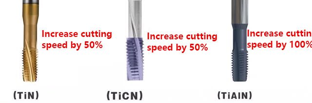
Cutting speed increased by more than 50%
Key to the success of tapping
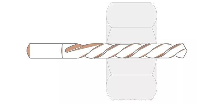
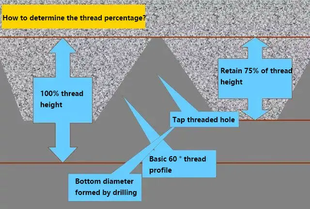
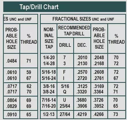
1) Determine thread percentage
The size of the drilled hole determines the percentage of the thread bottom diameter and the thread height.
The larger the drill diameter used, the smaller the ratio of thread height achieved.
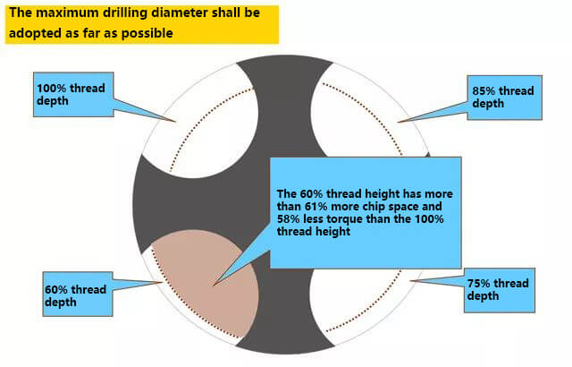
2) Selection of bottom hole size
Typically, a thread height ratio of 65% to 70% is preferred.
While a thread strength of 83% height is only 2% higher than that of 65% height, the tapping torque is more than double.
3) Frequently asked questions
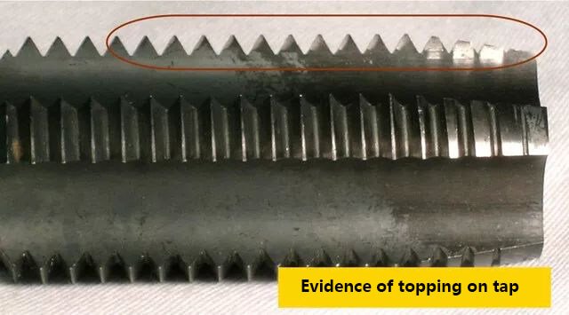
① Causes of tap top cutting
Manual tapping: the manual feed is not coordinated, and the feed is too fast or too slow.
Machine tapping: asynchronous tapping cycle is not programmed properly.
Lead Screw Machine Tool: Backlash caused by a worn lead screw or loose lead screw adjusting nut.
Cam Feed Machine: Incorrect or worn cam profile.
Pneumatic or Hydraulic Machine Tools: Uncontrollable pressure, either too high or too low.
Gear Feed Machine: Backlash caused by improper gear adjustment or wear.
② Solve the problem of tap top cutting
For the most accurate threads, the feed rate should be synchronized with the spindle speed.
The feed rate and spindle rotation must match the thread pitch.
6) Advantages of synchronous tapping of CNC machine tool:
Thread depth control, consistent hole-to-hole size, elimination of roof cutting, and retapping when necessary are important factors in tapping.
Question: If a CNC machine programmed with the G84 tapping cycle is operated manually, does it mean that rigid tapping can be performed?
Answer: No! Many CNC machine tools have a fixed tapping program with a feed rate in the form of drilling. These programs cannot be synchronized with the spindle.
Beware! The machine tool data must indicate whether the machine tool has “synchronous” or “rigid” tapping capabilities.
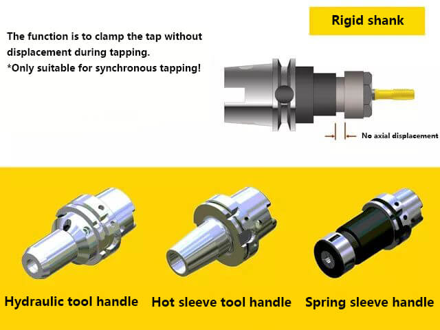
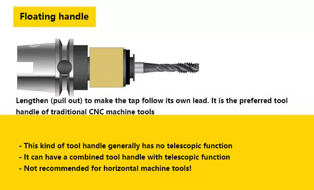
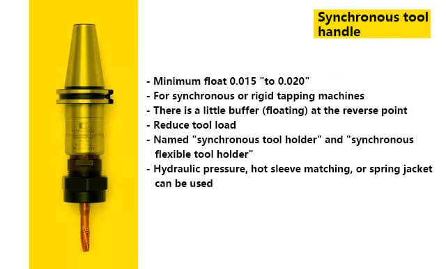
7) Selection of tool handle
For asynchronous tapping:
CNC machine tool with a fixed tapping cycle
Cam, gear, pneumatic, or hydraulic feed mechanism
For synchronous tapping:
In cases of oversize or undersize threads
8) Tool handle maintenance
Proper tool holder maintenance is crucial for producing high-quality threads and extending the service life of taps.
The internal mechanism should be kept free of chips and debris.
Lubricate regularly to ensure smooth movement of components and prevent rust.
Frequently check the tool handle, especially when using water-soluble coolants.
Troubleshooting
1) Excessive thread
Tapping NC setting
When tapping with CNC machine tools without a rigid tapping cycle:
Program the feed rate to 95% to 98% of the tap reverse stroke.
Use only extended tool handles or telescopic tool handles with compression locking.
When tapping on CNC machine tools with a rigid tapping cycle:
The tap lead is programmed to a feed rate of 100%.
Use an integral shank or synchronous shank.
If the end of the thread gauge is exceeded during topping:
Reprogram and follow the “non-rigid” procedure.
Consider using quick-change fittings to minimize “float.
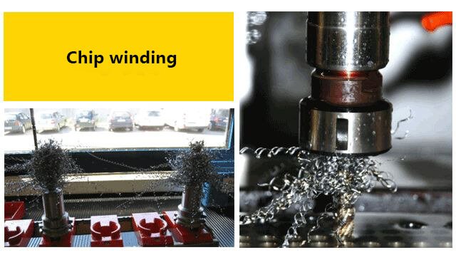
2) Chip winding
Change tap form
→ straight groove
→ smaller helix angle
Shorten cutting tap
Change front corner shape
Increase the number of slots
Change speed
Smaller hook
In case of rigid tapping, increase the pecking cycle
Consider extrusion tap
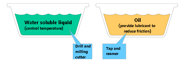
3) Lubrication selection
The purpose of lubrication in tapping is to reduce friction.
Therefore, lubricants are generally used for tapping, not coolants.
If a coolant is used, add EP (ultra-high pressure) or HP (high pressure) additives.
The tap has a fixed, large feed rate that is controlled by the tap pitch, while the drilling feed can be adjusted to control the load.
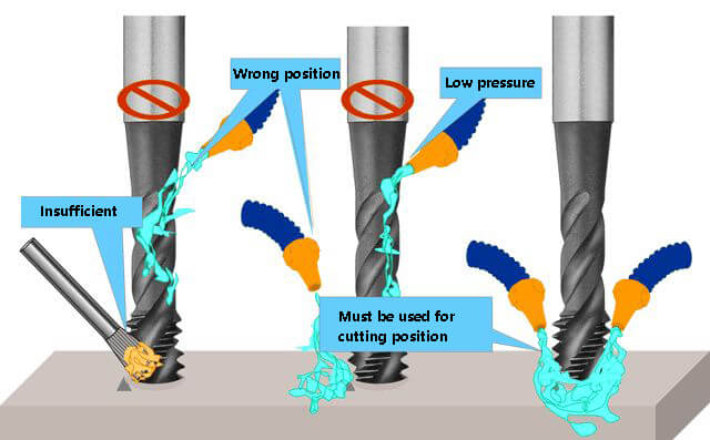
4) Coolant application
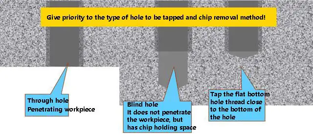
Tap selection basis
Before selecting a tap, we need to understand:
Type of hole, through hole, blind hole or deep hole
As the founder of MachineMFG, I have dedicated over a decade of my career to the metalworking industry. My extensive experience has allowed me to become an expert in the fields of sheet metal fabrication, machining, mechanical engineering, and machine tools for metals. I am constantly thinking, reading, and writing about these subjects, constantly striving to stay at the forefront of my field. Let my knowledge and expertise be an asset to your business.
Attention all mechanical engineers and manufacturing professionals! Are you struggling with pesky anodizing defects in your aluminum products? Look no further! In this blog post, we'll dive deep into the…
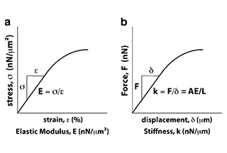
Ever wondered why some materials bend easily while others remain rigid? This blog dives into the fascinating world of elastic modulus and stiffness, unraveling their crucial roles in engineering. By…
Have you ever wondered what makes a perfect circle? In the world of mechanical engineering, roundness is a crucial concept that affects the performance and longevity of rotating components. This…
In today's fast-paced manufacturing world, efficient deburring is crucial. With numerous methods available, choosing the right one can be daunting. In this blog post, we'll explore various deburring techniques, from…
Have you ever wondered what keeps the world spinning smoothly? The unsung heroes behind the scenes are bearings. These small but mighty components play a crucial role in reducing friction…
Gears are the unsung heroes of the mechanical world, quietly working behind the scenes to keep machines running smoothly. But have you ever wondered what materials these critical components are…
This article explores the top 5 cooling tower manufacturers shaping our world. Learn how these companies innovate to keep industries running smoothly and efficiently. Get ready to uncover the secrets…
Have you ever wondered what keeps our gas systems running smoothly and safely? In this article, we explore top gas regulator manufacturers, uncovering their innovations and contributions to the industry.…
Ever wondered why connecting copper and aluminum wires is problematic? This article explains the risks associated with connecting these two metals due to their differing electrochemical properties, which can lead…