I. Welding Current 1. Welding Current The appropriate welding current is selected based on welding conditions such as plate thickness, welding position, welding speed, and material parameters. In reality, adjusting the current on a CO2 welding machine means adjusting the wire feed speed. Therefore, the welding current of the CO2 welding machine must match the welding […]
The appropriate welding current is selected based on welding conditions such as plate thickness, welding position, welding speed, and material parameters. In reality, adjusting the current on a CO2 welding machine means adjusting the wire feed speed.
Therefore, the welding current of the CO2 welding machine must match the welding voltage, ensuring that the wire feed speed aligns with the melting capacity of the welding wire for the voltage, to maintain a stable arc length.
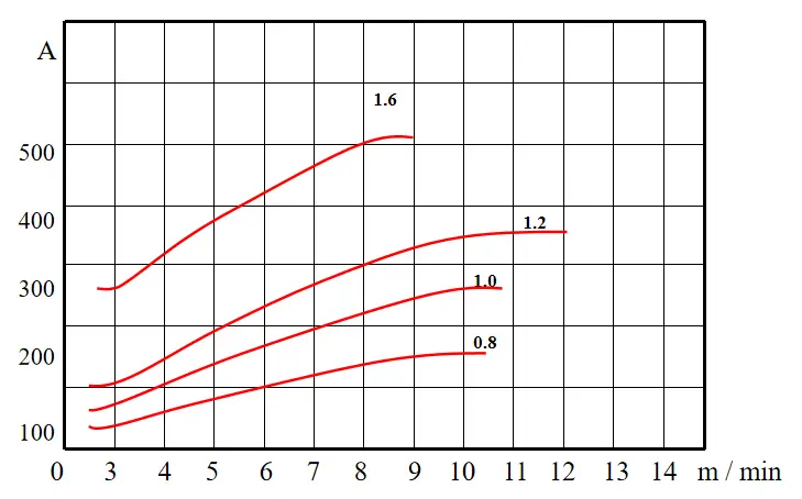
The Relationship between Welding Current and Wire Feed Speed
For the same welding wire, the greater the current, the faster the wire feed speed. With the same current, the thinner the wire, the faster the wire feed speed.
2. Welding Voltage
Welding voltage, also known as arc voltage, provides the energy for welding. The higher the arc voltage, the greater the welding energy, the faster the welding wire melts, and the greater the welding current.
The arc voltage equals the output voltage of the welding machine minus the voltage loss in the welding circuit, which can be represented by the following formula:
Arc Voltage = Output Voltage – Voltage Loss
If the welding machine is installed according to the installation requirements, the voltage loss mainly refers to the voltage loss caused by the extension of the welding cable. If your welding cable needs to be extended, you can refer to the following table when adjusting the output voltage of the welding machine.
Welding Current Cable Length
100A
200A
300A
400A
500A
10m
Approximately 1V
Approximately 1.5V
Approximately 1V
Approximately 1.5V
Approximately 2V
15m
Approximately 1V
Approximately 2.5V
Approximately 2V
Approximately 2.5V
Approximately 3V
20m
Approximately 1.5V
Approximately 3V
Approximately 2.5V
Approximately 3V
Approximately 4V
25m
Approximately 2V
Approximately 4V
Approximately 3V
Approximately 4V
Approximately 5V
II. Setting the Welding Voltage
Select the welding current according to the welding conditions for the corresponding plate thickness, and then calculate the welding voltage using the following formulas:
For < 300A: Welding Voltage = (0.05 × Welding Current + 14 ± 2) Volts
For > 300A: Welding Voltage = (0.05 × Welding Current + 14 ± 3) Volts
Example 1: Given a selected welding current of 200A, the welding voltage is calculated as follows:
Welding Voltage = (0.05 × 200 + 14 ± 2) Volts
= (10 + 14 ± 2) Volts
= (24 ± 2) Volts
Example 2: Given a selected welding current of 400A, the welding voltage is calculated as follows:
Welding Voltage = (0.05 × 400 + 14 ± 3) Volts
= (20 + 14 ± 3) Volts
= (34 ± 2) Volts
III. Selection of Welding Current
Welding voltage provides the energy necessary for the melting of the welding wire. Higher voltages result in a faster melting speed of the wire. Welding current, on the other hand, is essentially the balanced outcome of wire feeding speed and melting speed. So how should we choose the appropriate welding current?
1) The appropriate welding current value is selected based on factors such as the type of welding rod, plate thickness, and rod diameter.
The current is proportional to both plate thickness and wire diameter. The current (I) can be calculated using the formula I=(35-55)d, where ‘d’ is the rod diameter. For example, if the rod diameter is 4mm, the welding current value is selected between 140-220A.
2) Welding current is selected according to the welding position:
140A for overhead welding seams; between 140-160A for vertical and horizontal butt welding; over 180A for flat butt welding. For all-position welding (inclusive of flat, horizontal, vertical, and overhead positions), the selected welding current should be universal, usually taking the value of vertical welding current. When welding a horizontally fixed pipe for butt joint, the all-position welding current is used, generally taking the value of vertical butt welding current.
3) The current value is selected according to the welding layers:
A smaller current value is generally used for the root layer, a larger one for the filling layer, and the current value for the cover layer is relatively reduced. For example, in flat butt welding, a multi-layer, multi-pass welding approach is usually used.
The root layer is welded with a 150A current, while the filling layer can use a current value between 180-200A. The cover layer uses a reduced current value by 10-15A, to ensure an aesthetically pleasing result and avoid welding defects such as undercut.
4) Choosing welding current based on the type of welding rod and the method of manipulation:
1. According to the type of welding rod: Iacid > Ialkaline > Istainless steel. Acidic electrodes use the highest current value. When the electrode diameter is 4mm, the filler layer of flat butt welding can use a current of 180A.
However, with the same electrode diameter using an alkaline electrode, the welding current needs to be 20A less, i.e., a welding current of 160A. If welding is done with A137 stainless steel electrode, the current should be 20% less, approximately 140A. Otherwise, the welding rod may turn red and the flux layer may peel off halfway through the welding process.
2. Choosing based on manipulation method: Small current values are generally used for drag arc method, while slightly higher current values are used for lift arc method. When doing vertical butt welding or vertical angle welding with a Ф4 alkaline electrode, a drag arc method with 120A may be used, whereas the lift arc method can utilize 135A.
5) Choosing welding current based on production experience:
Look at the spatter, the welding current roughly decides the arc force, more spatter means more arc force; less welding current means less arc force, making it hard to distinguish between slag and molten metal.
Look at the weld formation: higher welding current is likely to cause undercutting, with less reinforcement; lower welding current results in a narrow but high weld. Observe the melting state of the electrode: a higher welding current melts the electrode faster, turning it red; a lower welding current might cause sticking.
IV. Impact of Welding Voltage on Welding Performance
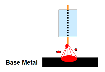
When the voltage is too high:
The arc length increases, spatter particles grow larger, porosity is more likely to occur, the weld bead widens, while the penetration depth and reinforcement decrease.
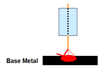
When the voltage is too low:
The welding wire dips into the base material, spattering increases, the weld bead narrows, while the penetration depth and reinforcement increase.
V. Standard Adjustment
Pre-fabrication is performed according to the reference formula prior to welding.
Trial Welding
Initially, the current is determined.
The voltage level is assessed based on tactile response, sound, and arc stability.
As the founder of MachineMFG, I have dedicated over a decade of my career to the metalworking industry. My extensive experience has allowed me to become an expert in the fields of sheet metal fabrication, machining, mechanical engineering, and machine tools for metals. I am constantly thinking, reading, and writing about these subjects, constantly striving to stay at the forefront of my field. Let my knowledge and expertise be an asset to your business.
Why is choosing the right mixed gas crucial for welding success? This article explores how selecting the appropriate gas mixture can dramatically improve welding quality by refining droplets, reducing splatter,…
Ever wondered how skyscrapers stand tall or cars stay welded together? This blog uncovers the magic behind electric welding machines. Learn about top manufacturers like Lincoln Electric and Miller Welds,…
Welding aluminum alloys presents unique challenges due to their low melting point and high thermal conductivity. This article dives into various welding methods, such as TIG, MIG, and plasma arc…
Choosing the right welding robot can transform your manufacturing process, but where do you start? This guide dives into crucial factors like degrees of freedom, load capacity, and working space.…
During the welding production process, there are many reasons why a welding robot might burn the contact tip. Observable symptoms indicating frequent replacement of the contact tip include: wear at…
Ever wondered how to keep welding robots in top shape and avoid costly downtime? This article covers essential maintenance tips for welding robots, emphasizing regular cleaning, proper storage, and timely…
Imagine a world where metals fuse seamlessly with just a spark. This is the essence of spot welding, a technique that binds metal parts with precision and strength. In this…
Imagine welding without gas – chaotic and weak. Welding gas is the silent champion, essential for shielding welds from contaminants, stabilizing the arc, and ensuring strong joints. This article explores…
Ever wondered how those sleek car bodies are welded together so seamlessly? This article dives into the world of spot welding machines, explaining their components, types, and applications across industries…