1. Method and Technique of Spot Welding.
1.1 Spot Welding Method.
Spot welding is generally divided into two categories: double-sided spot welding and single-sided spot welding. In double-sided spot welding, electrodes provide power to the welding area from both sides of the workpiece.
The typical methods of double-sided spot welding are shown in Figure 1. Figure 1a is the most commonly used method, where there are electrode marks on both sides of the workpiece.
Figure 1b shows the use of a conductive plate with a large contact area as the lower electrode, which can eliminate or reduce the marks left by the lower electrode and is often used for decorative panel spot welding.
Figure 1c depicts double-sided spot welding that simultaneously welds two or more weld points using a transformer to connect all electrodes in parallel.
At this time, the impedance of all current paths must be basically equal, and the surface state, material thickness, and electrode pressure at each welding position must be the same to ensure that the current passing through each welding point is basically the same.
Figure 1d shows double-sided multi-point spot welding using multiple transformers, which can avoid the shortcomings of Figure 1c.
In single-sided spot welding, electrodes provide power to the welding area from the same side of the workpiece. The typical methods of single-sided spot welding are shown in Figure 2.
Figure 2a is single-sided single-point spot welding, where the electrode that does not form a weld spot adopts a large diameter and a large contact area to reduce the current density.
Figure 2b is single-sided double-point spot welding without shunting, where all welding currents flow through the welding zone.
Figure 2c is single-sided double-point spot welding with shunting, where the current flowing through the upper workpiece does not pass through the welding zone, resulting in shunting. To provide a low-resistance path for the welding current, a copper pad is placed under the workpiece.
Figure 2d shows a special copper bridge A that is pressed together with the electrode on the workpiece to avoid improper heating, which can cause warping of the composite panel and reduce the resistance between the two electrodes when the distance between the two weld points l is large, such as in welding skeletal members and composite panels.

The spot welding with copper core rod is a special form of single-sided or double-sided spot welding. This form is particularly suitable for workpieces with limited space and where the electrode is difficult to approach or cannot be reached at all. The core rod shown in Figure 3a is actually a few millimeters thick copper plate.
Figures 3b and 3c show two types of similar structures, with structure 3b being inferior to structure 3c because the former reduces the heat generated in the welding area by passing through the diversion of workpiece 2 without passing through the contact surface of the two workpieces, thereby requiring an increase in welding current.
This will increase the heat generated between the contact surfaces of workpiece 2 and the two electrodes, and may even burn through the workpiece.
When the cross-sectional area of the core rod is large, copper plates can be wrapped or embedded into a core rod made of cloth glue wood or hardwood to save copper materials and facilitate production (as shown in Figures 3d and 3e).
Since the contact area between the core rod and the workpiece is much larger than the contact area between the electrode and the workpiece, the molten core will tend to shift towards the side of the workpiece in contact with the electrode.
If the thickness of the two workpieces is different, placing the thicker piece on the side of the core rod contact can reduce the degree of molten core shift.
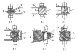
1 -copper core rod
2. 3 – Workpiece
4-Glue stick with cloth
5-copper clad plate
6- An embedded copper rod
7 – Filler
When welding workpieces on enclosed containers, and the core rod cannot be inserted into the container, the entire container can be filled with Zn, Pb, A1, or other metals with a lower melting point than the welded metal before welding (as shown in Figure 3f).
When the wall of the container is thick, non-conductive materials such as sand or paraffin can also be used as fillers. Strong conditions should be applied during welding to avoid long-term heating causing the low-melting-point metal or paraffin to melt, resulting in electrode pressure collapse on the workpiece.
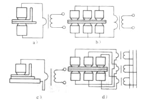
In mass production, single-sided multi-spot welding is widely used. At this time, a transformer can be used to supply power, and each pair of electrodes can press the workpiece in turn (as shown in Figure 4a), or each pair of electrodes can be powered by a separate transformer, and all electrodes can simultaneously press the workpiece (as shown in Figure 4b).
The latter form has more advantages and is more widely used. Its advantages are: each transformer can be placed closest to the connected electrode, so its power and size can be significantly reduced; the process parameters of each weld can be individually adjusted; all welds can be welded simultaneously, achieving high productivity; all electrodes press the workpiece at the same time, reducing deformation; multiple transformers are powered simultaneously, ensuring balanced three-phase loads.
1.2 Selection of Spot Welding Process Parameters.
Usually, the selection of spot welding process parameters is based on the material and thickness of the workpiece, with reference to the welding conditions table for that particular material.
First, determine the shape and size of the electrode end face. Secondly, preliminarily select the electrode pressure and welding time, and then adjust the welding current to weld samples with different currents.
After verifying that the molten core diameter meets the requirements, adjust the electrode pressure, welding time, and current within a suitable range, and carry out sample welding and inspection until the quality of the weld meets the requirements specified in the technical conditions.
The most commonly used method for inspecting samples is the tear test. The mark of a high-quality weld is a circular hole on one piece of the torn sample and a circular convex on the other piece.
In the case of thick plates or quenched materials, it may not be possible to obtain circular holes and convexes from tear tests, but the diameter of the molten core can be determined through shear fractures.
If necessary, low magnification measurement, tensile testing, and X-ray inspection should also be performed to determine the penetration rate, shear strength, and whether there are shrinkage holes, cracks, etc.

a) One transformer supplies power in turn.
b) Multiple transformers supply power separately to: 1. a hydraulic cylinder; 2. an electrode
When selecting process parameters based on test samples, it is necessary to fully consider the differences between the test samples and the actual workpiece in terms of diversion, the influence of ferromagnetic materials, assembly clearances, and make appropriate adjustments accordingly.
1.3 Spot Welding of Unequal Thickness and Different Materials
When conducting spot welding of unequal thickness or different materials, the molten core will be asymmetric with respect to the junction surface, and will shift towards the thicker side or the side with poorer conductivity and thermal conductivity. The result of this shift is a reduction in the penetration rate and strength of the thinner or better-conductive/better-heat-conductive workpiece.
Molten core shift is caused by differences in heat generation and dissipation between the two workpieces.
When the thickness is unequal, the thicker side has greater resistance and the junction surface is farther from the electrode, which results in more heat production and less dissipation, causing the molten core to shift towards the thicker side.
When the materials are different, materials with poor conductivity and thermal conductivity produce heat easily but dissipate it poorly, so the molten core also shifts towards these materials, as shown in Figure 5 where p represents the resistivity.
The principle of adjusting molten core shift is to increase the heat production of the thinner or better-conductive/better-heat-conductive workpiece and reduce its dissipation surface. Common methods include:
- Using electrodes with different contact surface diameters or spherical radii on the thinner or better-conductive/better-heat-conductive workpieces. The smaller diameter or radius is used on one side to increase the current density on that side and reduce the effect of electrode dissipation.

a)Unequal thickness(σ1<σ2)
b) Different materials(p1<p2)
2) Use electrodes made of different materials or conductors with good thermal conductivity, and use a copper alloy with poor thermal conductivity on one side of the workpiece to reduce heat loss on that side.
3) Use process pads to place a pad made of metal with poor thermal conductivity (with a thickness of 0.2-0.3mm) on one side of the workpiece or conductor with good thermal conductivity to reduce heat dissipation on that side.
4) The strong condition method is used – due to the short amount of time the electricity flows, the effect of indirect resistance heating between the workpieces increases, while the effect of electrode heat dissipation decreases, which is beneficial for overcoming melting core deviation.
This method has significant effects when spot welding thin and thick workpieces together. The capacitor stored energy welding machine (usually with high current and short electricity flow time) can spot weld workpieces with a thickness ratio of up to 20:1, serving as a clear example.
However, for thick workpieces, the contact resistance has little influence on melting core heating due to the longer electricity flow time.
In this case, weak conditions are actually more effective in allowing enough time for heat to transfer to the interface of the two workpieces, thus helping to overcome melting core deviation.
In production, there was an example where spot welding 5A06 (LF6) aluminum alloy with a thickness of 3.5mm (with high electrical resistance) and 2A14 (LD10) aluminum alloy with a thickness of 5.6mm (with low electrical resistance) resulted in serious melting core deviation towards the thinner 5A06 (IF6) workpiece. Only after extending the electricity flow time from 13Hz to 20Hz could the deviation be corrected.
2. Design of spot welding joints
Spot welding usually utilizes overlapping joints and folded edges (as shown in Figure 6). The joint can be composed of two or more workpieces with equal or unequal thickness.
When designing the spot welding structure, the accessibility of the electrode must be considered – that is, the electrode must be able to easily reach the welding area of the component. Additionally, factors such as edge distance, overlap amount, spacing between welds, assembly clearance, and weld strength should also be taken into account.
The minimum value of edge distance depends on the type of metal being welded, its thickness, and the welding conditions. A smaller value may be used for high yield strength metals, thin sheets, or when strong welding conditions are applied.

a) Overlapping joint
b) Folded edge joint: e – spacing between welds; b – edge distance
The overlap amount is twice the edge distance, and the recommended minimum overlap amount is shown in Table 1.
The spacing between welds refers to the center-to-center distance between adjacent spots, and its minimum value is related to the thickness, electrical conductivity, surface cleanliness of the metal being welded, as well as the diameter of the melting core. Table 2 shows the recommended minimum spacing between welds.
Table 1 Minimum recommended overlap amount for joints (unit: mm)
| Thickness of the thinnest plate | Min overlap of single row solder joints | Min overlap of double row solder joints | ||||
| Structural steel | Stainless steel and superalloys | Light alloy | Structural steel | Stainless steel and superalloys | Light alloy | |
| 0.5 | 8 | 6 | 12 | 16 | 14 | 22 |
| 0.8 | 9 | 7 | 12 | 18 | 16 | 22 |
| 1.0 | 10 | 8 | 14 | 20 | 18 | 24 |
| 1.2 | 11 | 9 | 14 | 22 | 20 | 26 |
| 15 | 12 | 10 | 16 | 24 | 22 | 30 |
| 20 | 14 | 12 | 20 | 28 | 26 | 34 |
| 25 | 16 | 14 | 24 | ·32 | 30 | 40 |
| 3.0 | 18 | 16 | 26 | 36 | 34 | 46 |
| 35 | 20 | 18 | 28 | 40 | 38 | 48 |
| 40 | 22 | 20 | 30 | 42 | 40 | 50 |
Table 2 Minimum recommended spacing between welds (unit: mm)
| Thickness of the thinnest plate | Minimum point distance | ||
| Structural steel | Stainless steel and superalloys | Light alloy | |
| 0.5 | 10 | 8 | 15 |
| 0.8 | 12 | 10 | 15 |
| 1.0 | 12 | 10 | 15 |
| 1.2 | 14 | 12 | 15 |
| 15 | 14 | 12 | 20 |
| 2.0 | 16 | 14 | 25 |
| 2.5 | 18 | 16 | 25 |
| 30 | 20 | 18 | 30 |
| 3.5 | 22 | 20 | 35 |
| 4.0 | 24 | 22 | 35 |
The minimum pitch is mainly considered for the diversion effect. When a strong condition and a large electrode pressure are used, the pitch can be appropriately reduced. When using thermal expansion monitoring or a controller that can sequentially change the current of each point, and when using other devices that can effectively compensate for the diversion effect, the pitch can be unrestricted.
If the pitch cannot be widened due to workpiece size limitations and there are no control measures mentioned above, in order to ensure consistent fusion core size, appropriate current must be used to first weld the first point of each workpiece, then increase the current and weld the adjacent points.
The assembly clearance must be as small as possible because relying on pressure to eliminate clearance will consume some of the electrode pressure, reducing the actual welding pressure.
The unevenness of the clearance will also cause fluctuations in the welding pressure, resulting in significant differences in the strength of each weld point. Excessive clearance will also cause serious splashing.
The allowable clearance value depends on the stiffness and thickness of the workpiece. The larger the stiffness and thickness, the smaller the allowable clearance, usually between 0.1~2mm. Excessive clearance of annular workpieces can be eliminated by rolling.
The shear strength of a single weld point depends on the area of the fusion core on the interface between the two plates. In order to ensure the joint strength, in addition to the fusion diameter, the penetration rate and indentation depth should also meet the requirements.
The penetration rate on each of the two plates should be measured separately. The penetration rate should be between 20% and 80%. The maximum penetration rate for magnesium alloy is only allowed up to 60%, while for titanium alloy it is allowed up to 90%. When welding workpieces of different thicknesses, the minimum penetration rate on each workpiece can be 20% of the thickness of the thinnest part of the joint.
The indentation speed should not exceed 15% of the plate thickness. If the ratio of the thicknesses of the two workpieces is greater than 2:1, or welding is carried out in hard-to-reach areas or on one side of the workpiece using a flat electrode, the indentation depth can be increased to 20%~25%. Figure 7 shows the fusion core size on a low-magnification grinding disc.

d is the fusion diameter; σ is the workpiece thickness; h is the fusion depth; c is the indentation depth.
The strength of spot welded joints under tensile loads perpendicular to the plate surface is the tensile strength.
Due to stress concentration caused by the acute angles formed between the two plates around the fusion zone, the actual strength of the fusion zone can be reduced, so spot welded joints are generally not loaded in this way.
Usually, the ratio of tensile strength to shear strength is used as an indicator to judge the ductility of the joint. The larger the ratio, the better the ductility of the joint.
The strength of a joint formed by multiple welds also depends on the pitch and distribution of the welds. When the pitch is small, the strength of the joint may be affected by diversion, while a large pitch will limit the number of welds that can be arranged.
Therefore, it is necessary to consider both the pitch and the number of welds to obtain the maximum joint tension. Multiple rows of welds are best arranged in a staggered pattern rather than a rectangular arrangement.
3. Spot Welding of Commonly Used Metals.
3.1 Workpiece Cleaning Before Resistance Welding
Whether spot welding, seam welding, or projection welding is used, the surface of the workpiece must be cleaned before welding to ensure stable joint quality.
Cleaning can be done through mechanical or chemical methods. Common mechanical cleaning methods include sandblasting, shot blasting, polishing, sanding with sandpaper, or wire brushes.
Different metals and alloys require different cleaning methods, which are summarized as follows:
The surface cleaning requirements for aluminum and its alloys are extremely strict because aluminum has a strong chemical affinity for oxygen. The surface that has just been cleaned will quickly oxidize and form an oxide film. Therefore, there is a strict time limit for how long the cleaned surface can be kept before welding.
The oxide film on aluminum alloys is mainly removed by chemical methods. After degreasing and rinsing in an alkaline solution, the workpiece is corroded in a phosphoric acid solution. In order to slow down the growth rate of the new film and fill the pores of the new film, passivation treatment is performed while corroding.
The most commonly used passivants are potassium dichromate and sodium dichromate (see Table 3). After passivation treatment, excessive corrosion of the workpiece surface will not occur when removing the oxide film.
After corrosion, rinse the workpiece and then perform brightening treatment in a nitric acid solution. Rinse it again after treatment, and dry the workpiece in a drying room at a temperature of 5℃, or blow-dry with hot air. After such cleaning, the workpiece can be kept for 72 hours before welding.
Mechanical methods can also be used to clean aluminum alloys. For instance, 0-00 number sandpaper or electric/fan-driven wire brushes can be utilized. However, to prevent damage to the workpiece surface, the wire diameter should not exceed 0.2mm, the length should not be shorter than 40mm, and the pressure of the brush on the workpiece should not exceed 5-20N. Moreover, welding must be performed within 2-3 hours after cleaning.
To ensure stable welding quality, various factories in China currently use wire brushes to clean the inner surfaces of overlapped workpieces after chemical cleaning.
After cleaning aluminum alloys, the total resistance between the two electrodes holding two aluminum alloy workpieces must be measured. A dedicated device similar to a spot welding machine is used for this purpose.
One of the electrodes is insulated from the electrode clamp, and the two test pieces are pressed together between the electrodes. The R value obtained in this way can most objectively reflect the quality of surface cleaning.
For 2A12, 7A04, and 5A06 aluminum alloys, R should not exceed 120uΩ, and the R value just after cleaning is usually 40-50uΩ. For aluminum alloys with better conductivity such as 3A21, 5A02, and sintered aluminum materials, R should not exceed 28-40uΩ.
Magnesium alloys are generally cleaned chemically, then passivated in a chromic acid solution.
This treatment forms a thin and dense oxide film on the surface that possesses stable electrical properties and can last for 10 days or longer, with almost no change in performance. Magnesium alloys can also be cleaned with wire brushes.
Copper alloys can be treated with nitric and hydrochloric acid, neutralized, and any welding residue removed.
When resistance welding stainless steel and high-temperature alloys, it is crucial to keep the workpiece surface highly clean, as the presence of oil, dust, or paint can increase the likelihood of sulfur embrittlement, leading to joint defects.
Cleaning methods include polishing, shot blasting, wire brushing, or chemical corrosion (see Table 3). For particularly important parts, electrolytic polishing is sometimes used, although this method is complex and has low productivity.
The oxide layer on titanium alloys can be removed by deep etching in a mixture solution of hydrochloric acid, nitric acid, and sodium phosphate. Wire brushing or shot blasting can also be used.
Low carbon steel and low alloy steel have a lower resistance to corrosion in the atmosphere.
Therefore, these metals are often protected during transportation, storage, and processing with anti-corrosion oils. If the oiled surface is not contaminated by dirt or other poorly conductive materials in the workshop, the oil film can be easily squeezed out under electrode pressure without affecting the joint quality.
Steel supply states include hot-rolled without acid pickling, hot-rolled with acid pickling and oil coating, and cold-rolled. When welding hot-rolled steel that has not been pickled, oxide layers must be removed using sandblasting, shot blasting, or chemical corrosion methods.
This can be done in sulfuric and hydrochloric acid solutions or in a solution mainly composed of phosphoric acid but containing thiourea (see Table 3), which can effectively remove oil residues and corrode the surface simultaneously.
Table 3 The composition of the solution used for chemical corrosion.
| Metal | Corrosion solution | Mixed solution | Allowable value |
| mild steel | 1. H2S04 200 g, NaCl 10g, buffer hexamethylenetetramine 1 g, temperature 50-60 ℃2. KHCl 200 g, hexamethylenetetramine 10g, temperature 30-40 ℃/2 per liter of water | Na0H or OH50-70g per liter of water, temperature 605 ℃ | 00 |
| Structural pot, low alloy steel | 1. H2S04 100g per liter of water, HC50g, 10g hexamethylene K-tetramine, temperature 50-60 ℃ 2. H3PO4 65-98g per 0.8L of water, Na3PO4 35-50g, emulsifier OP25g, thiourea 5g | 50~70g of NaOH or OH per liter of water at a temperature of 0-25 ℃; 35g of NaNO per liter of water at a temperature of 50-60 ℃ | 00 |
| Stainless steel, superalloy | In 0.75 L of water, H2S04110g, HCl130g, HNO3, 10g, temperature 50-70 ℃ 2 | Su solution with a mass fraction of 10% at a temperature of 20-15 ℃ | 000 |
| HC1416g,HNO370g,HF50g | |||
| Copper alloy | 1. HNO3 280g, HCl 1.5g, carbon black 1-2 g per liter of water, temperature 15 * 25 ℃ 2. HNO3100g, H2SO4180g HCl g per liter of water, temperature 15-25 ℃. 110~155g of HPO per liter of water | HNO3 per liter of water | 00 |
| aluminium alloy | K2Cr20, Na2Cr203: 1.5-0.8g, temperature 30-50 ℃, 0.3-0.5L water | 525g, temperature 20-85 ℃ | 0~120 |
| Magnesium alloy | Na0H300~600gNaN40~70gNaNo3150~250g, temperature 70~100 ℃ | 120~180 |
Steel plates with coatings generally do not require special cleaning for welding, except for a few exceptions. Galvanized steel plates, on the other hand, need to be cleaned using a wire brush or chemical corrosion.
Steel plates with a phosphate coating have such high surface resistance that welding current cannot pass through under low electrode pressure, and only higher pressure can be used for welding.
3.2 Spot welding of low carbon steel

Low carbon steel has a w(C) content of less than 0.25%. Its moderate resistance requires relatively low welding machine power; its broad plastic temperature range enables the required plastic deformation to be obtained without the need for large electrode pressure; its low carbon and trace element content, absence of high-melting-point oxides, generally do not produce quenched microstructures or inclusions; its narrow crystallization temperature range, low high-temperature strength, and small coefficient of thermal expansion make it prone to cracking.
This type of steel has good weldability, and its process parameters such as welding current, electrode pressure, and energizing time have a wide adjustment range.
Table 4 shows the recommended welding conditions for spot welding of low carbon steel by the American RWMA and can serve as a reference.
3.3 Spot welding of quenched steel
Due to its extremely fast cooling rate, hard and brittle martensite structure is inevitably produced when spot welding quenched steel, which can also lead to cracks under high stress.
In order to eliminate the quenched structure and improve joint performance, the double-pulse spot welding method after electrode-to-electrode welding and tempering is usually adopted.
Table 4 Welding conditions for spot welding of low carbon steel.
| Plate thickness/mm | Electrode | Minimum point distance/mm | Minimum overlap/mm | Optimum conditions | Moderate condition | General conditions | ||||||||||||||||||
| Maximum d/mm | Minimum D/mm | Electrode pressure/kN | Welding time/week | Welding current/kA | Nugget diameter/mm | Shear strength ± 14%/kN | Electrode pressure/kN | Welding time/week | Welding current/kA | Nugget diameter/mm | Shear strength ± 17%/kN | Electrode pressure/kN | Welding time/week | Welding current/kA | Nugget diameter/mm | Shear strength ± 20%/kN | ||||||||
| 0.4 | 3.2 | 10 | 8 | 10 | 1.15 | 5.2 | 4.0 | 1.8 | 0.75 | 8 | 4.5 | 3.6 | 1.6 | 0.40 | 17 | 3.5 | 3.3 | 1.25 | ||||||
| 0.5 | 4.8 | 10 | 9 | 11 | 1.35 | 5 | 6.0 | 4.3 | 2.4 | 0.90 | 9 | 5.0 | 4.0 | 2.1 | 0.45 | 20 | 4.0 | 3.6 | 1.75 | |||||
| 0.6 | 4.8 | 10 | 1.50 | 6.6 | 4.7 | 3.0 | 1.00 | 11 | 5.5 | 4.3 | 2.8 | 0.50 | 22 | 4.3 | 4.0 | 2.25 | ||||||||
| 0.8 | 4.8 | 10 | 12 | 11 | 1.90 | 7.8 | 5.3 | 4.4 | 1.25 | 13 | 6.5 | 4.8 | 4.0 | 0.60 | 25 | 5.0 | 4.6 | 3.55 | ||||||
| 1.0 | 6.4 | 13 | 18 | 12 | 2.25 | 8.8 | 5.8 | 6.1 | 1.50 | 7.2 | 5.4 | 5.4 | 0.75 | 30 | 5.6 | 5.3 | 5.3 | |||||||
| 1.2 | 6.4 | 13 | 20 | 14 | 2.70 | 10 | 9.8 | 6.2 | 7.8 | 1.75 | 19 | 7.7 | 5.8 | 6.8 | 0.85 | 33 | 6.1 | 5.5 | 6.5 | |||||
| 1.6 | 6.4 | 13 | 27 | 16 | 3.60 | 13 | 11.5 | 6.9 | 10.6 | 2.40 | 25 | 9.1 | 6.7 | 10.0 | 1.15 | 43 | 7.0 | 6.3 | 9.25 | |||||
| 1.8 | 8.0 | 16 | 31 | 17 | 4.10 | 15 | 12.5 | 7.4 | 13.0 | 2.75 | 28 | 9.7 | 7.1 | 11.8 | 1.30 | 48 | 7.5 | 6.7 | 11.00 | |||||
| 2.0 | 8.0 | 16 | 35 | 18 | 4.70 | 17 | 13.3 | 7.9 | 14.5 | 3.00 | 30 | 10.3 | 7.6 | 13.7 | 1.50 | 53 | 8.0 | 7.1 | 13.05 | |||||
| 2.3 | 8.0 | 16 | 20 | 5.80 | 20 | 15.0 | 8.6 | 18.5 | 3.70 | 37 | 11.3 | 8.4 | 17.7 | 1.80 | 64 | 8.6 | 7.9 | 16.85 | ||||||
| 3.2 | 9.5 | 16 | 50 | 22 | 8.20 | 27 | 17.4 | 10.3 | 31.0 | 5.00 | 50 | 12.9 | 9.9 | 28.5 | 2.60 | 88 | 10.0 | 9.4 | 26.60 | |||||
The first current pulse of this method is the welding pulse, and the second is the tempering heat treatment pulse. When using this method, two points should be noted:
- The time interval between the two pulses must ensure that the weld cools below the martensite transformation point Ms temperature;
- The amplitude of the tempering current pulse should be appropriate to avoid the metal in the welding zone from exceeding the austenite phase transition point again and causing secondary quenching.
An example of the dual-pulse spot welding process parameters for quenched steel is shown in Table 5 for reference. Although a long welding time (2-3 times longer than usual) can be used when using single-pulse spot welding to reduce the cooling rate of the joint, it still cannot avoid the formation of quenched microstructure.
When torn open for inspection, the joint shows brittle fracturing, with no round hole that can be pulled out, and its shear strength is much lower than that of a dual-pulse spot welded joint. Therefore, single-pulse spot welding is not recommended.
3.4 Spot welding of coated steel plates
The main problems during welding are as follows:
(1) The surface is easily damaged, losing the original function of the coating.
(2) The electrode easily adheres to the coating, shortening its lifespan.
(3) Compared with low carbon steel, the applicable range of welding process parameters is narrow and it is easy to form incomplete penetration or spatter; therefore, precise control of the process parameters is required.
(4) The melting point of the coating metal is usually lower than that of low carbon steel. When heated, the melted coating metal first enlarges the contact surface between the two plates, resulting in a decrease in current density. Therefore, the welding current should be higher than that without a coating.
(5) In order to expel the melted coating metal from the joint surface, the electrode pressure should be higher than that without a coating.
When welding steel plates with a polyvinyl chloride plastic surface, not only the necessary joint strength should be ensured but also the plastic surface should not be damaged. Therefore, single-side spot welding should be used, and a shorter welding time should be adopted.
(1) Spot welding of galvanized steel plates
Galvanized steel plates are roughly divided into electroplated galvanized steel plates and hot-dip galvanized steel plates, with the former having a thinner coating than the latter.
For spot welding galvanized steel plates, 2 types of electrode alloys are recommended. When high appearance requirements are needed for the welded joints, 1 type of alloy can be used. A tapered electrode shape with a cone angle of 120°~140° is recommended. When using welding tongs, a spherical electrode with a semi-end radius of 25-50mm is recommended.
To extend the lifespan of electrodes, a composite electrode embedded with a tungsten electrode head can also be used. An electrode body made of 2 types of electrode alloys can enhance the heat dissipation of the tungsten electrode head.
Table 6 shows the welding conditions for spot welding galvanized steel plates recommended by the third committee of the Japan Welding Society.
Effective ventilation devices should be used during spot welding of galvanized steel plates since ZnO dust is harmful to human health.
(2) Spot welding of aluminum-coated steel plates
Aluminum-coated steel plates are divided into two types. The first type is mainly heat-resistant with a surface coated with a 20-25um thick layer of Al-Si alloy (with Si content ranging from 6% to 8.5%), which can withstand temperatures of up to 640°C. The second type is mainly corrosion-resistant, with a pure aluminum coating thickness that is 2-3 times that of the first type. Good strength can be obtained when spot welding both types of aluminum-coated steel plates.
Table 5 25CrMnSiA、30CrMnSiAThe welding conditions for double-pulse spot welding of steel.
| Plate thickness | Electrode sector diameter/mm | Electrode pressure/kN | Welding time/week | Welding current/kA | Interval/week | Tempering time/week | Tempering current/kA |
| mm | |||||||
| 1.0 | 5~5.5 | 1~1.8 | 22-32 | 5-6.5 | 25-30 | 60-70 | 2.5~4.5 |
| 15 | 6~6.5 | 1.8~2.5 | 24-35 | 6-72 | 25-30 | 60-80 | 3-5 |
| 2.0 | 6.5-7 | 2-2.8 | 25-37 | 6.5~8 | 25-30 | 60-85 | 3.5-6 |
| 2.5 | 7~7.5 | 2.2~3.2 | 30-40 | 7~9 | 30~35 | 65-90 | 4-7 |
Due to the good electrical and thermal conductivity of the coating, a larger welding current is required for welding. Hard copper alloy spherical electrodes should be used.
Table 7 shows the welding conditions for type 1 aluminum-coated steel sheet spot welding. For type 2, a larger current and lower electrode pressure should be used due to the thicker coating.
(3) Lead-coated steel sheet spot welding. Lead-coated steel sheet is a low-carbon steel plate coated with a Pb-Sn alloy consisting of 75% w (Pb) and 25% w (Sn). This material is relatively expensive and less commonly used. Spot welding of lead-coated steel sheets is less common, and the process parameters used are similar to those of galvanized steel sheets.
3.5 Stainless steel spot welding
Stainless steel is generally divided into three types: austenitic stainless steel, ferritic stainless steel, and martensitic stainless steel. Due to the high resistance and poor thermal conductivity of stainless steel, compared with low-carbon steel, smaller welding currents and shorter welding times can be used.
These materials have high temperature strength and require higher electrode pressure to prevent defects such as shrinkage holes and cracks. Stainless steel is thermally sensitive and usually requires short welding times, strong internal and external water cooling, and accurate control of heating time and welding current to prevent grain growth in the heat-affected zone and intergranular corrosion.
For spot welding of stainless steel, it is recommended to use class 2 or class 3 electrode alloys to meet the needs of high electrode pressure. Table 8 shows the welding conditions for stainless steel spot welding.
Martensitic stainless steel tends to quench during spot welding, requiring a longer welding time. To eliminate quenched structures, it is best to use post-weld tempering. Double-pulse spot welding is generally not cooled externally to prevent cracking caused by quenching.
3.6 Spot welding of high-temperature alloys
High-temperature alloys are divided into iron-based and nickel-based alloys, with higher resistance and high-temperature strength than stainless steel, requiring smaller welding currents and larger electrode pressures. To reduce defects such as cracks and whiskers during spot welding of high-temperature alloys, overheating at the weld point should be avoided as much as possible.
Class 3 electrode alloys are recommended for reducing electrode deformation and consumption. Table 9 shows the recommended welding conditions for high-temperature alloy spot welding.
When spot welding thicker plates (2mm or more), it is best to apply a slow cooling pulse and forging pressure after the welding pulse to prevent shrinkage holes and cracks. Spherical electrodes should also be used to facilitate fusion core compaction and heat dissipation.
Table 6 Welding conditions for spot welding of galvanized steel plate.
| Plating type | Electrogalvanizing | HOT DIP GALVANIZING | |||||
| Plating thickness/μm | 2~3 | 2-3 | 2-3 | 10~15 | 15-20 | 20-25 | |
| Welding conditions | Level | Plate thickness/mm | |||||
| 0.8 | 12 | 1.6 | 0.8 | 1.2 | 1.6 | ||
| Electrode pressure/AN | A | 2.7 | 3.3 | 45 | 27 | 3.7 | 45 |
| B | 2.0 | 2.5 | 32 | 17 | 2.5 | 3.5 | |
| Welding time/week | A | 8 | 10 | 12 | 8 | 10 | 12 |
| B | 10 | 12 | 15 | 10 | 12 | 15 | |
| Current/kA | A | 10.0 | 11.5 | 14.5 | 10.0 | 12.5 | 15.0 |
| B | 8.5 | 10.5 | 12.0 | 9.9 | 11.0 | 12.0 | |
| Shear strength/kN | A | 4.6 | 67 | 115 | 5.0 | 9.0 | 13 |
| B | 4.4 | 6.5 | 10.5 | 4.8 | 8.7 | 12 | |
Table 7 Welding conditions for spot welding of heat-resistant aluminized steel plate.
| Plate thickness/mm | Electrode spherical radius/mm | Electrode pressure/kN | Welding time/week | Welding current/kA | Shear strength/kN |
| 0.6 | 25 | 1.8 | 9 | 8.7 | 1.9 |
| 0.8 | 25 | 2.0 | 10 | 9.5 | 2.5 |
| 1.0 | 50 | 2.5 | 11 | 10.5 | 4.2 |
| 1.2 | 50 | 3.2 | 12 | 12.0 | 6.0 |
| 1.4 | 50 | 4.0 | 14 | 13.0 | 8.0 |
| 2.0 | 50 | 5.5 | 18 | 14.0 | 13.0 |
Table 8Welding conditions for spot welding of stainless steel.
| Plate thickness/mm | Electrode end face diameter/mm | Electrode pressure/kN | Welding time/week | Welding current/A |
| 0.3 | 3.0 | 0.8-1.2 | 2-3 | 3-4 |
| 0.5 | 4.0 | 1.5-2.0 | 3-4 | 3.5-4.5 |
| 0.8 | 5.0 | 2.4-3.6 | 5-7 | 5-6.5 |
| 1.0 | 5.0 | 3.6-4.2 | 6-8 | 5.8-6.5 |
| 1.2 | 6.0 | 4.0~4.5 | 7-9 | 6.0-7.0 |
| 1.5 | 5.5~6.5 | 5.0-5.6 | 9-12 | 6.5~8.0 |
| 2.0 | 9.0 | 7.5~85 | 11-13 | 8-10 |
| 2.5 | 7.5-8.0 | 8.5-10 | 12-16 | 8-11 |
| 3.0 | 9-10 | 10-12 | 13-17 | 11~13 |
Table 9 Welding conditions for high-temperature alloys GH44 and GH33.
| Plate thickness/mm | Electrode end face diameter/mm | Electrode pressure/kN | Welding time/week | Welding current/kA |
| 0.3 | 3.0 | 4-5 | 7-10 | 5-6 |
| 0.5 | 4.0 | 5-6 | 9-12 | 4.5-5.5 |
| 0.8 | 5.0 | 6.5~8 | 11-17 | 5-6 |
| 1.0 | 5.0 | 8-10 | 16~20 | 6~6.5 |
| 12 | 6.0 | 10-12 | 19-24 | 6.2-6.8 |
| 1.5 | 5.5~6.5 | 12.5-15 | 22~31 | 6.5-7 |
| 20 | 7.0 | 15.5-17.5 | 29-38 | 7-7.5 |
| 2.5 | 7.5-8 | 18.5-19.5 | 39-48 | 7.5-82 |
| 3.0 | 9-10 | 20-21.5 | 50-65 | 8-8.8 |
3.7 Spot welding of aluminum alloys
Aluminum alloys are widely used and can be divided into two categories: cold-worked reinforced and heat-treated reinforced. The weldability of aluminum alloy spot welding is poor, especially for heat-treated reinforced aluminum alloys. The reasons and process measures to be taken are as follows:
(1) Due to the high electrical conductivity and thermal conductivity of aluminum alloys, a larger current and shorter time must be used to produce enough heat to form a molten pool while reducing surface overheating, avoiding electrode adhesion and electrode copper ions diffusing to the pure aluminum cladding layer, and reducing the corrosion resistance of the joint.
(2) Due to the narrow range of plasticity temperature and large linear expansion coefficient, a larger electrode pressure and good electrode follow-up performance must be used to avoid cracks caused by excessive internal tensile stress when the molten pool solidifies.
For aluminum alloys with a large tendency to crack, such as 5A06, 2A12, LC4, etc., the forging pressure should be increased to ensure sufficient plastic deformation of the molten pool during solidification, reduce tensile stress, and prevent cracks from occurring.
When the bending electrode cannot withstand a large top forging pressure, cracks can also be avoided by adding a slow cooling pulse after the welding pulse. Both methods can be used for thick aluminum alloys.
(3) The surface of aluminum alloys is prone to generate oxide films, so it must be strictly cleaned before welding; otherwise, it is easy to cause splashing and poor formation of the molten pool (when torn open for inspection, the shape of the molten pool is irregular and the boss and hole are not round), which will reduce the strength of the weld. Uneven cleaning will cause unstable strength of the weld.
Based on the above reasons, the welding machine for spot welding aluminum alloys should have the following characteristics:
1) Ability to provide large current in a short time;
2) The current waveform should have a slow rise and fall;
3) Precise control of process parameters without being affected by power grid voltage fluctuations;
4) Ability to provide stepped and saddle-shaped electrode pressure;
5) Small inertia and frictional force of the machine head, good electrode follow-up performance.
The currently used 300~1000kVA direct current pulse, three-phase low frequency and secondary rectification welding machines (some of which can reach up to 1000kVA) all have the above characteristics.
Single-phase AC welding machines do not have these features and are only suitable for spot welding of insignificant workpieces, with welding machine power generally not exceeding 400KVA.
The electrode for spot welding aluminum alloy should use a Class 1 electrode alloy with a spherical end face to facilitate compression and solidification of the molten core, as well as heat dissipation.
Due to high current density and the presence of oxide film, it is easy to cause electrode sticking when spot welding aluminum alloy. Electrode sticking not only affects the appearance quality but also reduces joint strength due to decreased current. Therefore, electrodes need to be regularly sharpened.
The number of welds that can be made after each sharpening of the electrode depends on factors such as welding conditions, the type of metal being welded, cleaning condition, whether there is current waveform modulation, electrode material, and cooling condition.
Usually, spot welding pure aluminum is from 5 to 80 points, while spot welding 5A06 and 2A12 is from 25 to 30 points.
Rust-proof aluminum 3A21 has low strength, good ductility, and good weldability without cracking. Fixed and unchanging electrode pressure is usually used.
Hard aluminum (such as 2A11, 2A12), ultra-hard aluminum (such as 7A04) have high strength and poor ductility, and are prone to cracking. The pressure of the stepped curve must be used.
However, for thin parts, large welding pressure or double pulse heating with slow cooling may also prevent cracking.
When using stepped pressure, it is important to have a lag time between the moment of power-off and the forging pressure, usually from 0 to 2 weeks. If the forging pressure is applied too early (before power off), it will increase the welding pressure, affect heating, and reduce and fluctuate the strength of the weld. If the forging pressure is applied too late, cracks will have formed when the molten core cools and crystallizes, and adding forging pressure will be ineffective.
Sometimes, it is necessary to apply forging pressure before power-off because the electromagnetic gas valve has a delay in action or the gas path is not smooth, resulting in slow increase of forging pressure, which is not enough to prevent cracking if not applied in advance.
The welding conditions for spot welding aluminum alloy on direct current pulse welding machines are shown in Tables 12-11 and 12-12. When using a three-phase secondary rectification welding machine, Table 10 and 11 can be referred to, but the welding time needs to be appropriately extended, and the welding current needs to be reduced.
Table 10 Welding conditions for spot welding of aluminum alloy 3A21, 5A03, and 5A05.
| Plate thickness/mm | Electrode spherical radius/mm | Electrode pressure/kN | Welding time/week | Welding current/kA | Forging pressure/kN |
| 0.8 | 75 | 2.0~2.5 | 2 | 25-28 | – |
| 1.0 | 100 | 2.5-3.6 | 2 | 29-32 | – |
| 1.5 | 150 | 3.5-4.0 | 3 | 35~40 | – |
| 2.0 | 200 | 4.5-5.0 | 5 | 45~50 | – |
| 2.5 | 200 | 6.0~6.5 | 5-7 | 49-55 | – |
| 3.0 | 200 | 8 | 6-9 | 57-60 | 22 |
Table 11 Welding conditions for spot welding of aluminum alloy 2A12CZ and LC4CS.
| Plate thickness/mm | Electrode spherical radius/mm | Electrode pressure/AN | Welding time/week | Welding current/kA | Forging pressure/AN | Forging lag power off time/week |
| 0.5 | 75 | 23~3.1 | 1 | 19-26 | 3.0-3.2 | 0.5 |
| 0.8 | 100 | 3.1~3.5 | 2 | 26~36 | 5.0-8.0 | 0.5 |
| 1.0 | 100 | 3.6~4.0 | 2 | 29-36 | 8.0-9.0 | 0.5 |
| 1.3 | 100 | 4.0~4.2 | 2 | 40~46 | 10-10.5 | 1 |
| 1.6 | 150 | 5.0~5.9 | 3 | 41-54 | 13.514 | 1 |
| 18 | 200 | 6.8~7.3 | 3 | 45~50 | 15~16 | 1 |
| 2.0 | 200 | 7.0~9.0 | 5 | 50~55 | 19~19.5 | 1 |
| 2.3 | 200 | 8.0~1.0 | 5 | 70-75 | 23~24 | 1 |
| 2.5 | 200 | 8.0~11 | 7 | 80-85 | 25~26 | 1 |
| 3.0 | 200 | 11~12 | 8 | 90~94 | 30~32 | 2 |
3.8 Spot welding of copper and copper alloys:
Compared to aluminum alloys, copper alloys have slightly higher resistivity and poorer thermal conductivity, so spot welding is not particularly difficult.
Copper alloys with a thickness of less than 1.5mm, especially low-conductivity copper alloys, are the most widely used in production. Pure copper has extremely high electrical conductivity, and spot welding is more difficult.
Usually, shims are added between the electrode and the workpiece, or a composite electrode with tungsten embedded in the electrode head is used to reduce heat dissipation towards the electrode. The diameter of the tungsten rod is usually 3~4mm.
When welding copper and high-conductivity brass and bronze, class 1 tungsten alloy electrodes are generally used. When welding low-conductivity brass, bronze, and copper-nickel alloys, class 2 electrode alloys are used. Copper alloys can also be welded using a composite electrode embedded with tungsten.
Because tungsten has poor thermal conductivity, much smaller welding currents can be used for spot welding on commonly used medium-power welding machines. However, the tungsten electrode is prone to stick to the workpiece, affecting the appearance of the workpiece. Tables 12 and 13 show the welding conditions for spot welding brass.
Copper and high-conductivity copper alloys are rarely spot welded due to severe electrode adhesion. Even with composite electrodes, only thin copper plates can be spot welded.
3.9 Spot welding of titanium alloys:
Titanium alloys have high specific strength, strong corrosion resistance, and good thermal strength, and are therefore widely used in aerospace and chemical industries.
The weldability of titanium alloys is similar to that of stainless steel, and the process parameters are roughly the same. Generally, no special cleaning is required before welding, and acid pickling can be performed when there is an oxide film.
Titanium alloys have strong thermal sensitivity, and even under strong conditions, the grains will grow significantly. The weld penetration can reach 90%, but it has no significant effect on the quality. Its welding conditions can refer to Table 14.
Due to the high-temperature strength of titanium alloys, class 2 electrode alloys with a spherical end face are best used for electrodes.
3.10 Adhesive spot welding of aluminum alloys:
Compared with pure spot welding, adhesive spot welding has the following advantages:
1) Improved structural strength. Its static shear strength is more than twice that of spot welding, and its fatigue strength is 3 to 5 times that of spot welding.
2) Good sealing performance. It can prevent metal corrosion caused by residual acid in the lap joints during post-welding anodization.
However, adhesive spot welding has higher costs, longer curing time for adhesives, and greater energy consumption than pure spot welding.
There are mainly three methods for adhesive spot welding:
1)Apply adhesive before spot welding.
2)Spot weld first and then inject adhesive. The injection method is to use a glue gun to inject the adhesive into the lap joint.
3)Insert a layer of solid adhesive film between the two workpieces to match the lap width. Punch a hole slightly larger than the weld size in the adhesive film at the location where spot welding is needed, and then spot weld at the position with the hole in the adhesive film.
The first method requires a longer active period for the adhesive, and strict requirements for the temperature, humidity, and waiting time after adhesive application in the workplace. When the viscosity of the adhesive increases to a certain extent, it will affect the welding because the electrode pressure cannot squeeze out the adhesive.
It is not suitable to use a hard pulse with a sharp rise in current in capacitor storage welding machine for adhesive spot welding after adhesive application. Because excessively hard pulses often cannot extrude all the adhesive from the joint surface, and the residual adhesive in the joint may cause defects such as looseness, pores, and cracks.
Excessively soft current pulses are also not recommended because they will cause a rapid decrease in the viscosity of the adhesive, leading to adhesive flow and detachment. The current waveform of the DC pulse spot welding machine has a slow rise and fall, which is suitable for adhesive spot welding. When using AC spot welding, an amplitude modulation waveform is recommended.
When spot welding after applying the adhesive, the extruded adhesive will contaminate the electrode, affecting the operation and product quality. Moreover, the post-welding deformation must be corrected before the adhesive is cured, which adds difficulties to production.
The second method requires that the adhesive has good fluidity to facilitate filling the lap joint. However, excessive fluidity is also not recommended as it may cause adhesive loss. When injecting the adhesive, to facilitate the adhesive entering the weld seam without flowing onto other surfaces, the workpiece should be inclined at an angle of 15° to 45°.
The disadvantage of spot welding first and then injecting adhesive is that the width of the lap joint is limited. When the width exceeds 40mm, the uneven lap joint surface after spot welding makes it difficult for the adhesive to penetrate the entire lap joint and form a complete bond, resulting in adhesive defects.
The spot welding first and then injecting adhesive method is simple and easy to ensure quality, and excess adhesive can be easily removed.
Therefore, this method is widely used in domestic production. Modified epoxy adhesives are generally used for adhesive spot welding. Adhesive grades for spot welding first and then injecting adhesive include 425-1, 425-2, TF-3, and SY201.
Adhesive spot welding has been widely used in aircraft manufacturing. For example, the connection between the skin and stringers of China’s domestically produced “Yun-7” aircraft has adopted this technology on a large scale.
Table 12 The welding conditions for brass spot welding.
| Plate thickness/mm | Electrode pressure/AN | Waveform modulation/cycle | Welding time/week | Welding current/kA | Shear strength/kN | |
| 0.8+0.8 | 3 | 3 | 6 | 23 | 15 | |
| +1.6 | 3 | 3 | 6 | 23 | – | |
| +23 | 3 | 3 | 8 | 22 | – | |
| +3.2 | 3 | 3 | 10 | 22 | – | |
| 1.2+1.2 | 4 | 3 | 8 | 23 | 2.3 | |
| 1.6+1.6 | 4 | 3 | 10 | 25 | 2.9 | |
| +2.3 | 4.5 | 3 | 10 | 26 | – | |
| +3.2 | 4.5 | 3 | 10 | 26 | – | |
| 2.3+2.3 | 5 | 3 | 14 | 26 | 5.3 | |
| +3.2 | 6 | 3 | 14 | 31 | – | |
| 3.2+3.2 | 10 | 3 | 16 | 43 | 8.5 | |
Table 13 The welding conditions for spot welding brass using composite electrodes.
| Plate thickness/mm | Electrode pressure/kN | Welding time/week | Welding current/kA | Shear resistance/kN |
| 0.4 | 0.6 | 5 | 8 | 1 |
| 0.6 | 0.8 | 6 | 9 | 1.2 |
| 0.8 | 1.0 | 8 | 9.5 | 2 |
| 1.0 | 12 | 11 | 10 | 3 |
Table 14 The welding conditions for spot welding titanium alloy [Ti-6Al-4V (α+β)].
| Plate thickness/mm | Electrode pressure/kN | Welding time/week | Welding current/kA | Solder joint strength/kN | |
| tensile strength | Shear strength | ||||
| 0.9 | 2.7 | 55 | 2.7 | 7.8 | |
| 1.5 | 6.8 | 10 | 10.5 | 4.5 | 22 |
| 18 | 7.5 | 12 | 11.5 | 84 | 28 |
| 23 | 11.0 | 16 | 12.5 | 9S | 38 |