Bend Allowance Formula: Calculator & Charts
Have you ever wondered how to precisely calculate the bending allowance for your metal fabrication projects? In this blog post, we'll explore the fascinating world of bend allowance formulas and…
Have you ever wondered why some tubes wrinkle or tear during bending? This article explores the root causes of these issues, focusing on factors like bending radius, material properties, and machine settings. By understanding these variables, you can enhance the quality of your tube bending projects, reduce waste, and improve overall efficiency. Get ready to uncover practical solutions for achieving smooth, defect-free bends in your tubes.
In the fabrication of automotive exhaust pipes and similar tubular parts, quality issues such as wrinkles or tears frequently occur due to factors such as bending radius and material properties. It is particularly crucial to reduce or eliminate these problems in order to enhance product quality and lower scrap rates.
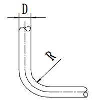
The bending process for tubes is comparable to that of sheet metal: the outer wall of the neutral layer is subjected to tensile stress, thinning the wall, while the inner wall of the neutral layer experiences compressive stress, thickening the wall. Excessive deformation can lead to cracks in the outer wall and wrinkling in the inner wall. Table 1 presents the minimum bending radii for steel tubes.
Table 1: Minimum Bending Radius (R) for Steel Tubes
 | Wall Thickness | Minimum Bending Radius R |
| 0.02D | 4D | |
| 0.05D | 3.6D | |
| 0.10D | 3D | |
| 0.15D | 2D |
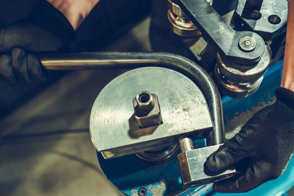
The methods of tube bending generally include: bending with manual tube bending tools; bending with dedicated tube bending machines; anti-deformation method of bending; cold extrusion bending; mold pressing to form elbows; core rod hot extrusion bending. This article primarily focuses on the use of dedicated tube bending machines as examples to analyze wrinkling and tearing issues.

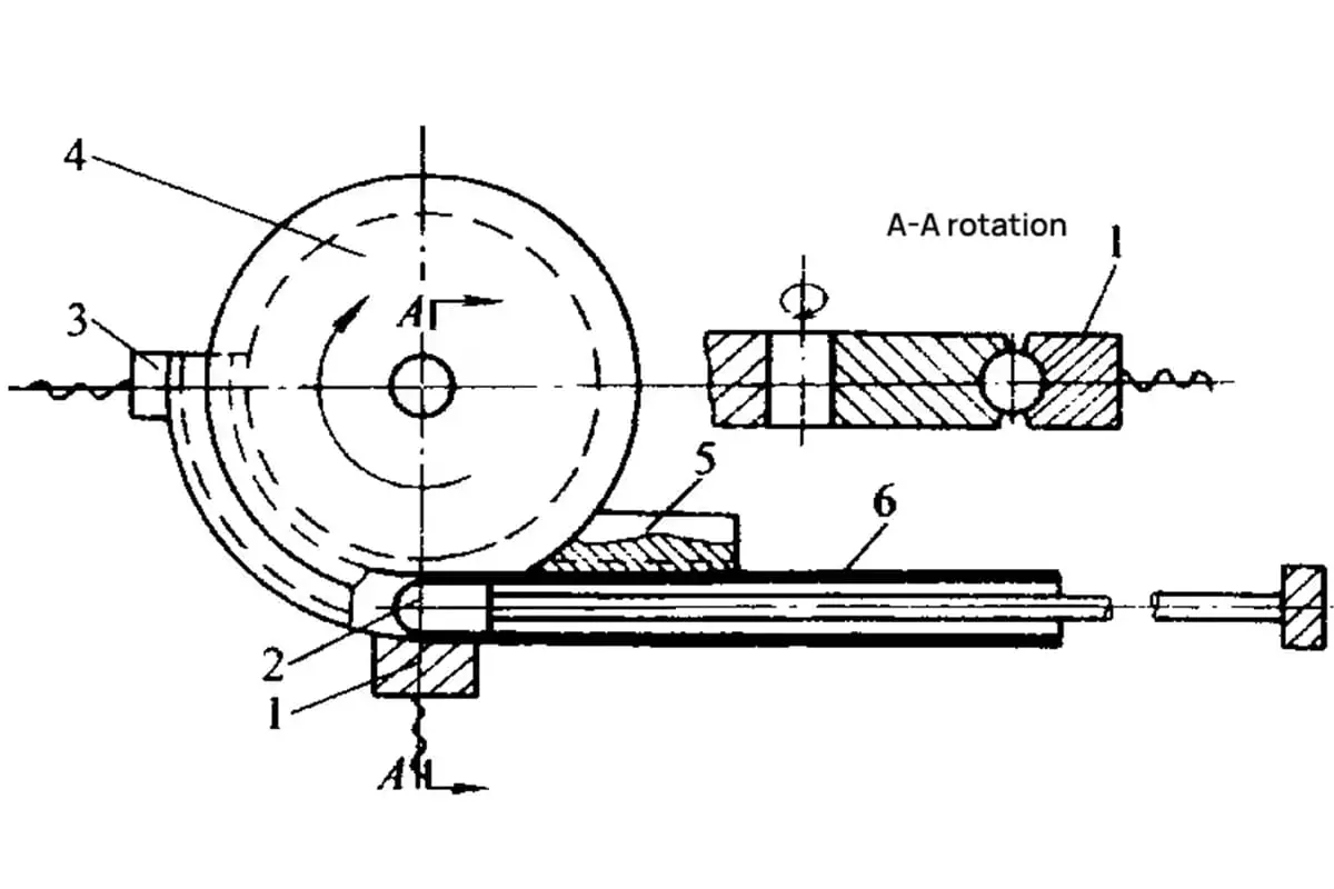
1. Mandrel
2. Guide Plate
3. Die
4. Pressure Block
5. Tube Component
The dedicated pipe bender typically uses a mandrel for bending. The process involves mounting the die, item 3, on a rotatable spindle of the machine. Before the pipe is bent, it is clamped onto the die by the pressure block, item 4. A mandrel, item 1, is inserted inside the pipe. When the machine starts, the pipe material gradually bends around the die to take shape.
During the bending process, a smaller bending radius could potentially cause wrinkling on the inner side or even cracks on the outer wall. The design must take into account the pipe’s wall thickness, outer diameter, and material properties. Table 1 should be referred to when choosing the bending radius.
Empirically, when using a regular cylindrical mandrel for bending, the minimum bending radius can be slightly smaller than what is stated in Table 1, as long as it doesn’t cause wrinkling or cracking. When a smaller bending radius is required, the pipe wall thickness can be increased, the outer diameter reduced, and a material with good ductility and smooth exterior should be selected.
3.2.1 Working Position of the Mandrel
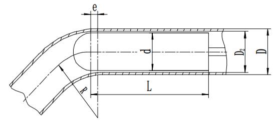
In core bending of tubes, the shape and operating position of the mandrel have a significant impact on the bending quality of the tube. Typically, the diameter d of the mandrel should be 0.5-1.5mm smaller than the inner diameter of the tube, facilitating insertion into the tube.
The distance e from the point where the mandrel enters the tube to the start of the bending process (see Figure 2) can be calculated using the following empirical formula.

In the equation,
3.2.2 Selection of Mandrel Shape
There are various mandrel shapes, roughly divided into: standard cylindrical mandrels, spoon-shaped mandrels, chain-link mandrels, and flexible shaft mandrels. The standard cylindrical mandrel is often used due to its simple structure, ease of manufacture, and easy removal after bending.
However, since the contact area between the mandrel and the tube wall is small, it is less effective in preventing the creation of an elliptical shape.
The length of the mandrel, denoted as L, should be (see Fig. 2)
L = (3 to 5) d mm
When the diameter d of the mandrel is large, the coefficient takes a smaller value, and vice versa.
3.2.3 Control of the Gap Between the Mandrel and the Inner Wall of the Pipe Fittings
If the gap between the mandrel and the inner wall of the pipe fittings is too large, at the beginning of the bending process, the mandrel and the pipe wall do not fully touch, leading to severe wrinkling on the inner side of the pipe fittings, and the occurrence of dead bends. If the gap is too small, when clamping a regular welded pipe, the irregular height of the weld on the inner wall of the pipe fitting can make the mandrel difficult to insert into the pipe fitting.
Through a long period of summarizing bending pipe work, the author has determined a more appropriate gap between the inner wall of the pipe and the mandrel:
c = D2 – d = 0.5 to 1.5 mm.
In standard pipe bending operations on bending machines, guide plates (Figure 1) clamp the workpiece and move synchronously with it. The speed of this guide plate is adjustable, and its movement speed directly influences the quality of the bent pipe.
The workpiece, clamped by the press block onto the die, contains a mandrel within it. As the machine operates, the pipe material gradually bends around the die, with the guide plate moving forward in sync with the die’s speed. During this process, static friction between the guide plate and workpiece acts on the workpiece.
If the guide plate’s speed is higher than the die’s, it imparts a forward thrust to the workpiece; conversely, it applies a resistance force if its speed is less. Bending tests show that under equal conditions, if the guide plate’s speed substantially exceeds the die’s linear speed, wrinkles tend to form on the pipe’s inner wall.
Conversely, if the guide plate’s speed significantly lags, the pipe’s outer wall noticeably thins, even to the point of tearing. Therefore, effectively adjusting the guide plate’s thrust speed to match the die’s is crucial for ensuring bending quality.
From this analysis, it’s clear that the guide plate’s thrust speed must be synchronized with the bending speed during the bending process. Hence, before bending or after changing to a different bending radius die, it is necessary to adjust the guide plate’s speed accordingly.
As shown in Figure 1, the bending speed α and bending radius R are preset. The arc length that the bending die should turn, i.e., the distance the guide plate should move forward synchronously in the same time, is calculated. The bending machine idles while the operator slowly rotates the speed control valve handle, observing the guide plate’s movement.
After bending to the set angle and stopping, the guide plate’s actual displacement is measured with a ruler, comparing it with the theoretical calculation. If they differ, the idle adjustment can be repeated until the measured value matches the calculated value.
In reality, due to load factors, the guide plate’s movement speed during actual bending is often slower than during idling. Therefore, when adjusting the guide plate’s thrust speed, the actual value can be slightly higher than the theoretical value.
In conclusion, the presence of wrinkles, tears, or elliptical deformities in the pipe is an important measure of bending quality.
These quality defects can be minimized by selecting a suitable bending radius, an appropriate mandrel shape, controlling the gap between the mandrel and the pipe’s inner wall, adjusting the mandrel’s insertion position, and the guide plate’s movement speed.

As the founder of MachineMFG, I have dedicated over a decade of my career to the metalworking industry. My extensive experience has allowed me to become an expert in the fields of sheet metal fabrication, machining, mechanical engineering, and machine tools for metals. I am constantly thinking, reading, and writing about these subjects, constantly striving to stay at the forefront of my field. Let my knowledge and expertise be an asset to your business.