Pipe Bending Torque Calculations: Detailed Guide
Have you ever considered the forces at play when bending a pipe? In this article, we'll explore the fascinating world of pipe bending mechanics. Our expert mechanical engineer will break…
Have you ever marveled at the intricate curves and bends of industrial pipes? In this blog post, we’ll explore the fascinating world of pipe bending equipment and calculations. Our expert mechanical engineer will guide you through the process, sharing insights and examples to help you understand this critical aspect of industrial design and fabrication.
Pipe bending can be categorized into three types: drawn bends, press bends, and welded bends.
Drawn bends can be further divided into cold drawn and hot drawn. This chapter primarily introduces the structural features, capabilities, and operation of commonly used pipe bending equipment, along with the calculation for pipe bending material.
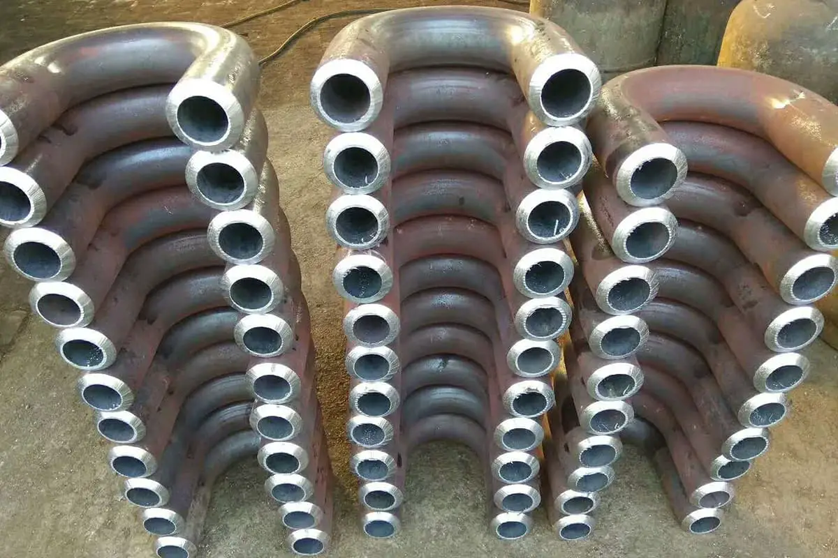
A bent pipe is a pipe fitting that changes the direction of the pipeline. Bent pipes can be seen where pipes cross, bend, or wrap around beams.
Drawn bent pipes have excellent expandability, high pressure resistance, and low resistance, making them commonly used in construction.
The main forms of bent pipes include various angles of elbows, U-shaped pipes, back-and-forth bends (also known as Z-bends), and curved pipes, as shown in Figure 1-1.
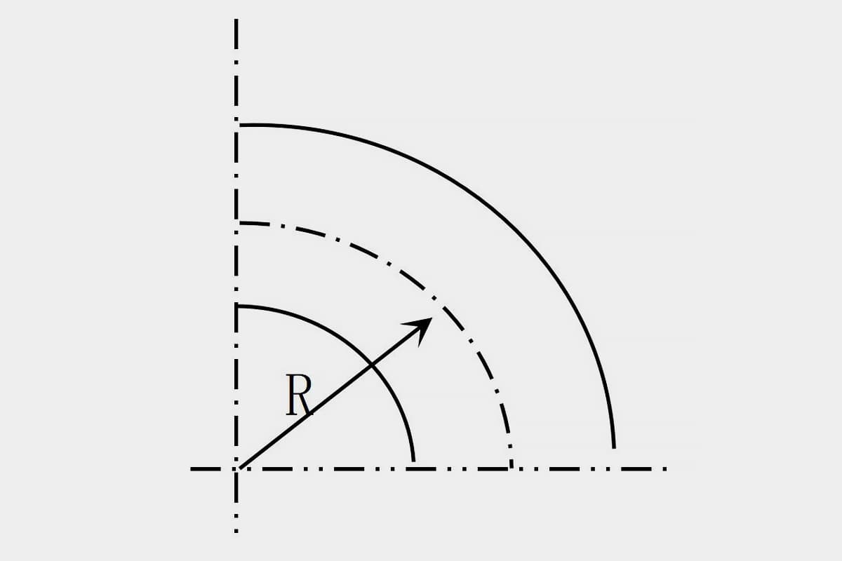
An elbow is a pipe fitting with an arbitrary bending angle, used at the bends of a pipe. The bending radius of the elbow is represented by R. When R is larger, the bending part of the pipe is larger, making the bend smoother. When R is smaller, the bending part of the pipe is smaller, resulting in a sharper bend.
A back-and-forth bend is a pipe fitting with two bending angles (usually 135°). The distance between the centerlines of the bent ends of a back-and-forth bend pipe is called the height of the back-and-forth bend, represented by the letter h. It is generally used when connecting indoor heating risers with mains and radiators, and when connecting pipes with junctions that are not on the same plane.
A U-shaped pipe is a semicircular pipe fitting. The distance d between the centerlines of the two ends of the pipe equals twice the bending radius R. U-shaped pipes can replace two 90° elbows and are often used to connect two round-wing radiators arranged vertically.

The curved tube is fitting with three bending angles. The middle angle is generally 90°, and the side angles are 135°. Curved tubes are used to bypass other pipes, and are often used in sanitary equipment piping with hot and cold water supplies.
The size of the bent tube is determined by the tube diameter, bending angle, and bending radius. The bending angle is determined according to the drawings and the actual situation of the construction site, and then a template is made. The bent tube is made according to the template and checked whether the bending angle of the fabricated tube fitting meets the requirements.
The template can be fabricated with round steel, the diameter of the round steel is chosen based on the size of the tube diameter to be fabricated, 10-14mm is sufficient. The bending radius of the bent tube should be determined according to the pipe diameter size, design requirements, and relevant regulations. It should not be too large, nor arbitrarily chosen to be too small.
Because if the bending radius is too large, not only it uses more material, but the place occupied by the bent part of the pipe is also larger, which may cause difficulties in pipe assembly; if the bending radius is chosen to be too small, the pipe wall at the back of the bend is overly elongated and thinned, reducing its strength, and the pipe wall on the inside of the bend is compressed, forming a wrinkled state.
Therefore, it is generally stipulated: the bending radius of hot-bent tubes should not be less than 3.5 times the outer diameter of the pipe; the bending radius of cold-bent tubes should not be less than 4 times the outer diameter of the pipe; the bending radius of welded elbows should not be less than 1.5 times the pipe’s outer diameter; the bending radius of punched elbows should not be less than the pipe’s outer diameter.
When bending the tube, the metal on the inside of the bend is compressed, and the pipe wall thickens; the metal on the back of the bend is stretched, and the pipe wall thins. The smaller the bending radius, the more severe the thinning of the pipe wall at the back of the bend, and the greater the impact on the back strength.
In order to prevent the original working performance of the pipe from changing too much after bending, it is generally stipulated that after the pipe is bent, the pipe wall thinning rate should not exceed 15%. The pipe wall thinning rate can be calculated according to the following formula:
A=[1-R/(R+DW/2)]×100%
In the formula:
During pipe bending, due to the change in the thickness of the inner and outer walls of the bent segment of the pipe, the cross-sectional shape of the bent segment changes from a circle to an ellipse. The change in the shape of the bent pipe cross-section reduces the flow cross-sectional area of the pipe, thereby increasing fluid resistance, and also reducing the pipe’s ability to withstand internal pressure.
Therefore, the following stipulations are generally made for the ellipticity of bent pipes: When the pipe diameter is less than or equal to 150mm, the ellipticity should not exceed 10%; when the pipe diameter is less than or equal to 200mm, the ellipticity should not exceed 8%.
The ellipticity of the pipe can be calculated according to the following formula:
T=(d1-d2)/d1×100%
Where:
When making cold or hot mandrel bending pipes with water, gas steel pipes, and longitudinally welded steel pipes, the weld of the pipe should be located at a place 45° from the centerline of the side, as shown in Figure 1-2. This is to prevent the weld of the pipe from cracking during bending.

Generally, wrinkles are not allowed to develop during the bending of the pipe. If there are individual uneven areas, their height should not exceed the following limits: when the diameter is less or equal to 125mm, it should not exceed 4mm; when the diameter is less or equal to 200mm, it should not exceed 5mm.
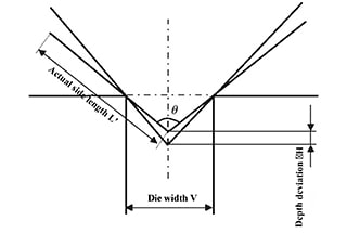
Before carrying out the pipe bending work, the length of the bent section of the pipe must be calculated first, and the starting point of the bend must be marked so that the correct semi-finished part can be obtained after bending.
90° bending pipes are most widely used in pipeline engineering, and their bending radius varies due to different manufacturing methods. For cold bending pipes, R=(4~6)D is usually taken; for hot bending pipes, R=4D is taken; for stamping elbows or welded elbows, R=(1~1.5)D is usually taken. After the bending radius is determined, the cutting length of the bending part can be calculated, and the heating length during hot bending can be determined, as shown in Figure 1-3.
As can be seen from the figure, after the pipe is bent, the outer arc and the inner arc of the bent section are not the actual lengths of the original straight pipe, but only the length of the centerline of the bent pipe remains unchanged before and after bending, and its unfolded length is equal to the original straight pipe section length. Now, let’s assume the start and end points of the bent section are a and b.
When the bending angle is 90°, the length of the bent section of the pipe is exactly 1/4 of the circumference of the circle drawn with radius r, and its arc length is represented by the bending radius, which is
Arc length ab=2πR/4=1.57R
From equation (1-3), it can be known that the unfolded length of the 90° bent pipe is 1.57 times the bending radius.

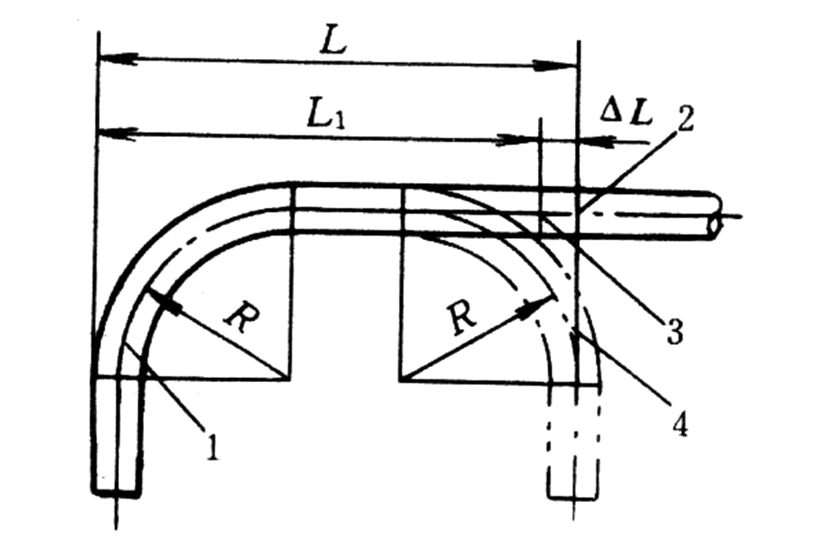
When bending a U-shaped bend, a reverse double bend, or a square expander, if the center distance of the two adjacent 90° bends is drawn and formed according to the design requirements or actual measurements, then the center distance of the two bends will be larger than the original distance.
This is a result of the extension produced when the metal pipe is heated and bent. When cutting, the extension error should be subtracted from the center distance of the two bends, and then the center line and heating length of the second bend should be drawn.
In this way, after the two bends are bent, the distance between the center lines will be exactly the required dimension. The extension error is shown in Figure 1-4 and can be calculated using the following formula:

Where:

Taking a square expander as an example, the method of bending pipe scribing and blanking calculation is explained. In Figure 1-5a, the unit of the square expander’s size is known to be mm, the diameter of the pipe is DN150, and the bending radius R=4DN=600mm. If the scribing is done on the straight line in Figure 1-5b, starting from the left end point o, it can be seen from the figure that Oa=1500-R=1500-600=900mm. ab is the bent part, and its arc length is ab=1.57R=1.57 x 600=942mm.
From a to d, it consists of two opposite 90° bends and a straight pipe section bc. The length of the straight pipe section bc should subtract the extension error △L, then bc=2100-2R-△L.
From equation (1-4) it can be known that △L=600x(1-0.00875×90)=127.5mm. So bc=2100-2×600-127.5=772.5mm.
Similarly, the blanking length of each pipe section can be calculated. As shown in Figure 1-5b, the scribing work can be carried out smoothly. In actual work, when making pipe fittings composed of multiple bends, the scribing work is completed in several times.
First, calculate the blanking length of each section on the sketch, and select a straight pipe of appropriate length. Then start making each bend from one end. After the previous bend is made, scribe the next one to deal with the size error in the pipe bending work.

Arbitrary bends refer to bends with arbitrary bend angles and arbitrary bend radii. The unfolded length of the bent part of this type of bend can be calculated by the following formula:
L=παR/180=0.01745αR
In the formula, L is the unfolded length of the bent part (mm); α— is the bending angle (°); π— is Pi; R is the bending radius (mm).
Additionally, the calculation of the unfolded length of any bent pipe section can also be conducted according to Figure 1-6 and Table 1-1.

The usage of Table 1-1 is explained in the following example.
Table 1-1 Calculation of Arbitrary Pipe Bending
| Bending Angle | Half Bending Length C | Bending Length L |
| 1 | 0.0087 | 0.0175 |
| 2 | 0.0175 | 0.0349 |
| 3 | 0.0261 | 0.0524 |
| 4 | 0.0349 | 0.0698 |
| 5 | 0.0436 | 0.0873 |
| 6 | 0.0524 | 0.1047 |
| 7 | 0.0611 | 0.1222 |
| 8 | 0.0699 | 0.1396 |
| 9 | 0.0787 | 0.1571 |
| 10 | 0.0875 | 0.1745 |
| 11 | 0.0962 | 0.1920 |
| 12 | 0.1051 | 0.2094 |
| 13 | 0.1139 | 0.2269 |
| 14 | 0.1228 | 0.2443 |
| 15 | 0.1316 | 0.2618 |
| 16 | 0.1405 | 0.2793 |
| 17 | 0.1494 | 0.2967 |
| 18 | 0.1584 | 0.3142 |
| 19 | 0.1673 | 0.3316 |
| 20 | 0.1763 | 0.3491 |
| 21 | 0.1853 | 0.3665 |
| 22 | 0.1944 | 0.3840 |
| 23 | 0.2034 | 0.4014 |
| 24 | 0.2126 | 0.4189 |
| 25 | 0.2216 | 0.4363 |
| 26 | 0.2309 | 0.4538 |
| 27 | 0.2400 | 0.4712 |
| 28 | 0.2493 | 0.4887 |
| 29 | 0.2587 | 0.5061 |
| 30 | 0.2679 | 0.5236 |
| 31 | 0.2773 | 0.5411 |
| 32 | 0.2867 | 0.5585 |
| 33 | 0.2962 | 0.5760 |
| 34 | 0.3057 | 0.5934 |
| 35 | 0.3153 | 0.6109 |
| 36 | 0.3249 | 0.6283 |
| 37 | 0.3345 | 0.6458 |
| 38 | 0.3443 | 0.6632 |
| 39 | 0.3541 | 0.6807 |
| 40 | 0.3640 | 0.6981 |
| 41 | 0.3738 | 0.7156 |
| 42 | 0.3839 | 0.7330 |
| 43 | 0.3939 | 0.7505 |
| 44 | 0.4040 | 0.7679 |
| 45 | 0.4141 | 0.7854 |
| 46 | 0.4245 | 0.8029 |
| 47 | 0.4348 | 0.8203 |
| 48 | 0.4452 | 0.8378 |
| 49 | 0.4557 | 0.8552 |
| 50 | 0.4663 | 0.8727 |
| 51 | 0.4769 | 0.8901 |
| 52 | 0.4877 | 0.9076 |
| 53 | 0.4985 | 0.9250 |
| 54 | 0.5095 | 0.9425 |
| 55 | 0.5205 | 0.9599 |
| 56 | 0.5317 | 0.9774 |
| 57 | 0.5429 | 0.9948 |
| 58 | 0.5543 | 1.0123 |
| 59 | 0.5657 | 1.0297 |
| 60 | 0.5774 | 1.0472 |
| 61 | 0.5890 | 1.0647 |
| 62 | 0.6009 | 1.0821 |
| 63 | 0.6128 | 1.0996 |
| 64 | 0.6249 | 1.1170 |
| 65 | 0.6370 | 1.1345 |
| 66 | 0.6494 | 1.1519 |
| 67 | 0.6618 | 1.1694 |
| 68 | 0.6745 | 1.1868 |
| 69 | 0.6872 | 1.2043 |
| 70 | 0.7002 | 1.2217 |
| 71 | 0.7132 | 1.2392 |
| 72 | 0.7265 | 1.2566 |
| 73 | 0.7399 | 1.2741 |
| 74 | 0.7536 | 1.2915 |
| 75 | 0.7673 | 1.3090 |
| 76 | 0.7813 | 1.3265 |
| 77 | 0.7954 | 1.3439 |
| 78 | O.8098 | 1.3614 |
| 79 | O.8243 | 1.3788 |
| 80 | 0.8391 | 1.3963 |
| 81 | 0.8540 | 1.4173 |
| 82 | O.8693 | 1.4312 |
| 83 | O.8847 | 1.4486 |
| 84 | 0.9004 | 1.4661 |
| 85 | 0.9163 | 1.4835 |
| 86 | 0.9325 | 1.5010 |
| 87 | 0.9484 | 1.5184 |
| 88 | O.9657 | 1.5359 |
| 89 | 0.9827 | 1.5533 |
| 90 | 1.000 | 1.5708 |
Note: When using the C and L values from the table, they should be multiplied by the bending radius R.
Example: Given that the bending angle of the elbow in Figure 1-7 is 25°, the bending radius R is 500mm, and the distance from the installed pipe section to the corner point M is 911mm. How should a straight pipe be marked to fabricate the elbow?
Solution: Length of the straight pipe section at the end of the pipe to be bent
b = 911 – CR
From Table 1-1, when the bending angle is 25°, C = 0.2216, L = 0.4363. Therefore, CR is calculated as:
0.2216R = 0.2216 x 500 = 111mm
Thus, b = 911 – 111 = 800mm
The actual unfolded length of the bent part
L = 0.4363R = 0.4363 x 500 = 218mm
The markings can be made according to the calculated straight pipe section length b and the unfolded length L of the bent part, as shown in Figure 1-7b.

As can be seen from the above example, as long as the bending angle and radius are determined, Table 1-1 can be used to conveniently calculate pipe bending at any angle and for any bend radius.
During hot bending, the length of the heated pipe section should generally be slightly longer than the bending length to ensure uniform heating of the bent part.
The added length is generally defined as: for pipes with a large bending angle, an additional length of twice the outer diameter of the pipe can be added; for those with a small bending angle, an additional 20% of the bending length can be added.
1. Arbitrary angle return bend
The arbitrary angle return bend can be divided into equal bend radius and unequal bend radius. Figure 1-8 is an arbitrary angle return bend with an equal bend radius. This type of pipe bend has five variable data: bend radius R, bend angle, bend distance H, bend pipe length A, and straight pipe length L.
In actual work, three data (H, R, and) can generally be determined according to the design or actual situation on site, and only two data (L, A) need to be determined by calculation.


Calculation of L and A values is divided into two scenarios:
1) When H≠2R

The total length of the back-and-forth bend is L+παR/90.
2) When H = 2R

The total length after bending and unfolding remains: L+παR/90.
Figures 1-9 are for bending back and forth with unequal bending radius. The blanking calculation can be performed according to the following formula.
Length of the straight pipe section between bends.

Total Length of the Pipe Bending Expansion

2. Calculation for Arc-shaped Bending Pipes
Arc-shaped bending pipes, also known as semi-circular bends or embracing bends, commonly come in angles of 45° and 60°, as shown in Figure 1-10. The formula for calculating the total length of material for a 45° arc-shaped bend is:
L=π/2(R+r)+2L
In the formula:

a) Angle is 45°
b) Angle is 60°
The formula for calculating the total material length for a 60° arc-shaped pipe is:
L=4πR/3
In the formula:
3. Crease Bend
The preparation method for crease bend is different from cold and hot bending. Its characteristic is that the total length of the back wall of the bend does not change before and after bending, while the inner wall of the bend produces regular creases due to local heating and bending.
Therefore, its marking method is completely different. The marking dimensions of various parts of the crease bend with a bending angle of 90 degrees can be calculated according to the following formula:
(1) The unfolded length of the outer arc L (mm)

(2) Width of the unheated area on the back of the bend, L1 (mm)
(3) Wrinkle Spacing a

In the formula,
The dimensions of the various parts of the 90° pleated elbow are listed in Table 1-2 for pipes with a nominal diameter of 100-600mm and a bend radius R=3DN. The dimensions of the various parts of the 90° pleated elbow under other common bending radii can be found in the relevant literature.
Next, we will use the steel pipe with a nominal diameter DNl25mm and a bending radius R=3DN as an example to explain how to use the sizes listed in Table 1-2 for the calculation of the pleated elbow.
According to the known conditions, first look up Table 1-2, and find R=375mm, a=117mm, L=700mm, n=7, b=89mm, m=28mm, L1=65mm.
Then draw two parallel lines AA/ and BB/ along the axis of the pipe, so that AA/=BB/=700mm, the end points A and B of the two lines are on the same circumference perpendicular to the axis of the pipe, and the distance between the two parallel lines (i.e., the arc length of arc AB) L1=65mm.
Divide the two lines AA/ and BB/ into 6 equal parts (n-1=6), each part is a=117mm, get the equal parts points Al, A2… and B1, B2… as shown in Figure 1-11.
Table 1-2R: Dimensions for marking a 90° pleated elbow with R: 3DN (m)
| Nominal Diameter DN | 100 | 125 | 150 | 200 | 250 | 300 | 350 | 400 | 450 | 500 | 600 |
| Outer Diameter of Pipe Dw | 108 | 133 | 159 | 219 | 273 | 325 | 377 | 426 | 480 | 530 | 630 |
| Bending Radius R | 300 | 375 | 450 | 600 | 750 | 900 | 1050 | 1200 | 1350 | 1500 | 1800 |
| Corrugation Spacing a | 92 | 117 | 139 | 184 | 199 | 209 | 216 | 247 | 250 | 252 | 277 |
| Outer Arc Length (Rounded to Integer) L | 550 | 700 | 830 | 1100 | 1395 | 1670 | 1945 | 2220 | 2500 | 2770 | 3320 |
| Number of Corrugations n | 7 | 7 | 7 | 7 | 0 | O | 10 | 10 | 11 | 12 | 13 |
| Maximum Width of Heated Part b | 64 | 89 | 106 | 142 | 150 | 153 | 160 | 184 | 187 | 189 | 207 |
| Minimum Width of Unheated Part m | 28 | 28 | 32 | 42 | 49 | 56 | 56 | 63 | 63 | 63 | 70 |
| Width of Non-heated Area L1 | 50 | 65 | 80 | 105 | 130 | 160 | 190 | 210 | 240 | 260 | 320 |

Draw a straight line OO’/ at the center of the opposite side of the pipe, cut b/2=44.5mm on both sides of each intersection point of the straight line O-O’/ with AB, A1B1, A2B2, etc., to get points T1, T2, as shown in Figure 1-11. Connect points A and B respectively to T3 and T4…, the area of these connecting lines is the folding part of the elbow.
Pipe bending is divided into cold bending and hot bending. Cold bending is the bending of the pipe at room temperature, which does not require sand filling or heating of the bending pipe section, making it easy to operate and saving manpower and material resources. It is most suitable for bending elbows of galvanized steel pipes, stainless steel pipes, and non-ferrous metal pipes such as copper and lead.
Cold bending of pipes must rely on machine tools. Commonly used cold bending equipment includes: manual pipe benders, electric pipe benders, and hydraulic pipe benders. With a cold pipe bending machine, elbows with a nominal diameter not exceeding 250mm can generally be bent. Medium frequency pipe benders are often used when bending large diameter thick-walled pipes.
When using cold bending equipment for pipe bending, the bending radius of the elbow should not be less than 4 times the nominal diameter of the pipe. When using a medium frequency pipe bender, the bending radius of the elbow only needs to be not less than 1.5 times the nominal diameter of the pipe.
Metal pipes have a certain elasticity. In the cold bending process, when the external force applied to the pipe is removed, the elbow will spring back to a certain angle. The size of the springback angle is related to the material of the pipe, the thickness of the pipe wall, and the size of the bending radius.
For general cold-bent carbon steel pipes with a bending radius of 4 times the nominal diameter of the pipe, the springback angle is approximately 3° to 5°. Therefore, when controlling the bending angle, this springback angle should be considered.
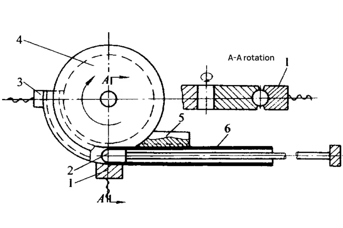
Manual pipe benders are divided into portable and fixed types. They can bend pipes with a nominal diameter not exceeding 25mm and generally need to be equipped with several sets of wheels corresponding to the common pipe outer diameter.
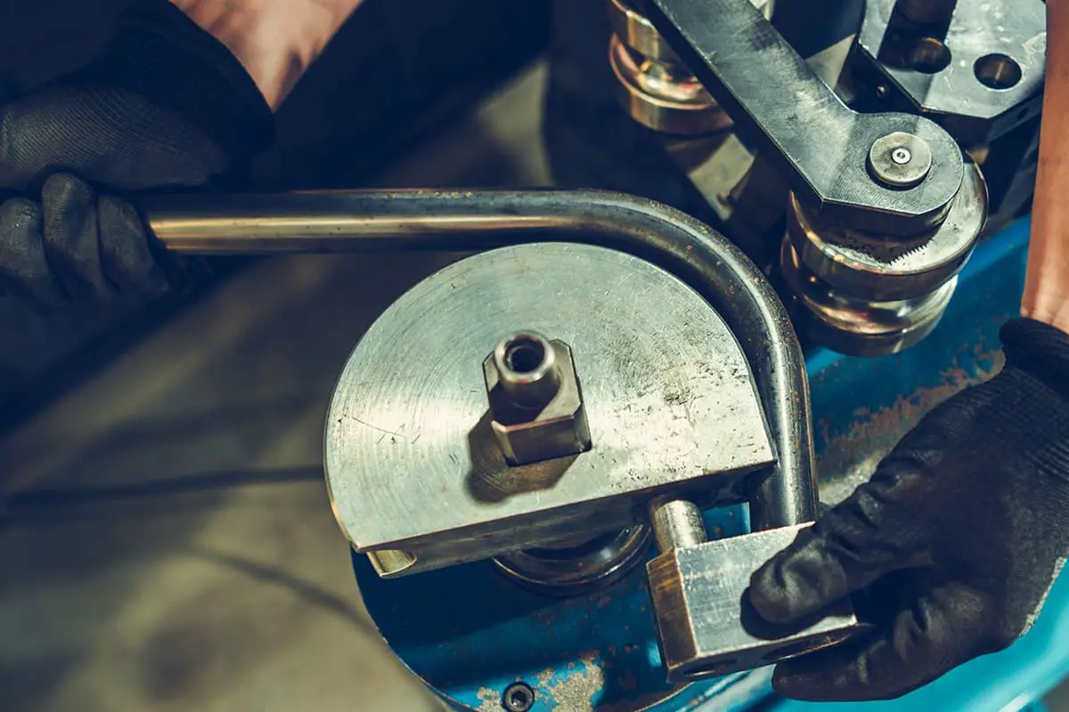
The structure of the portable manual pipe bender is shown in Figure 1-12. This pipe bender is made up of components such as a handle with a pipe bending die and a movable baffle.
During operation, the pipe to be bent is placed in the bending die groove, one end is fixed on the movable baffle, and the handle is pushed to bend the pipe to the required angle.
This pipe bender is characterized by its lightweight and flexibility, and it can be used for bending operations in any situation, making it most suitable for electrical and instrumentation piping.

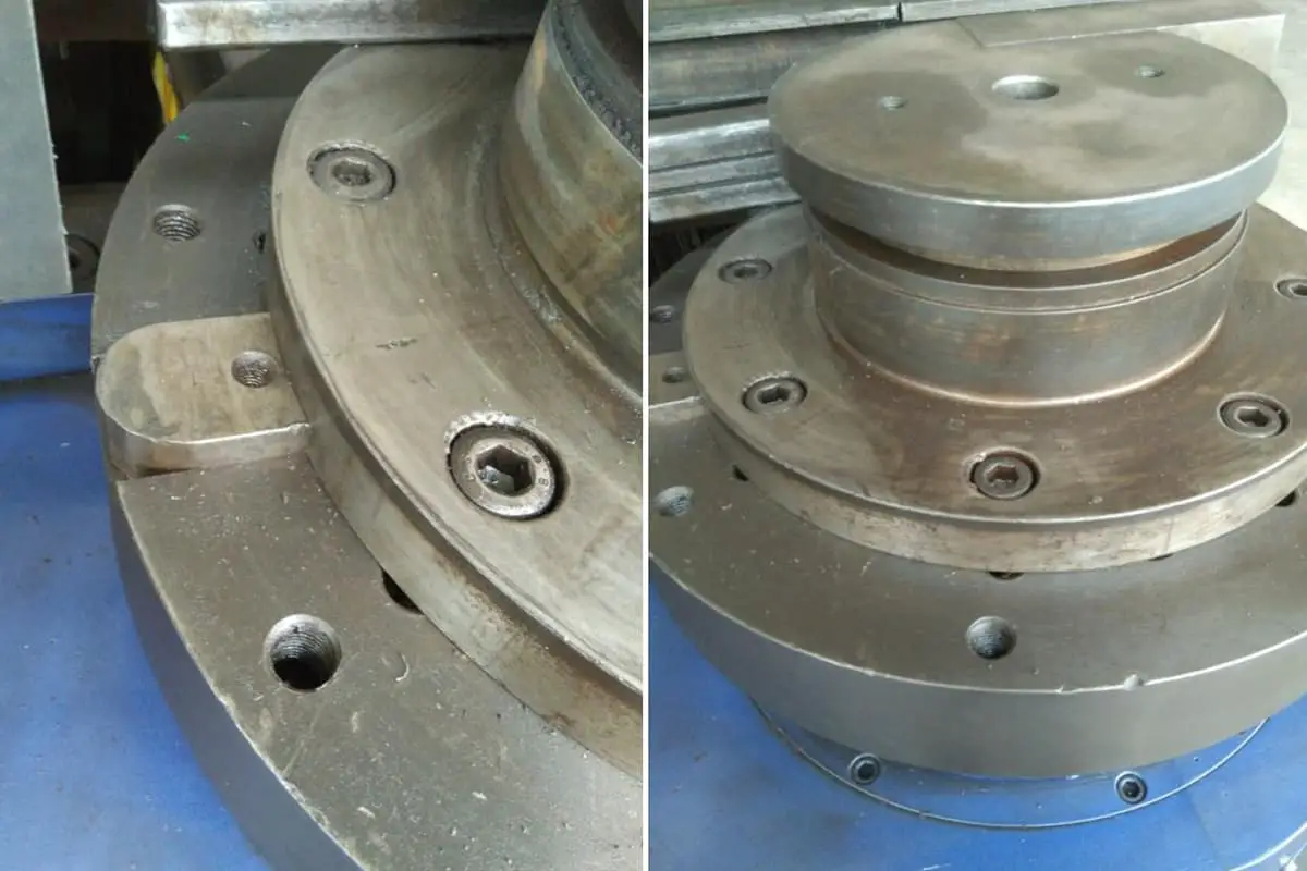
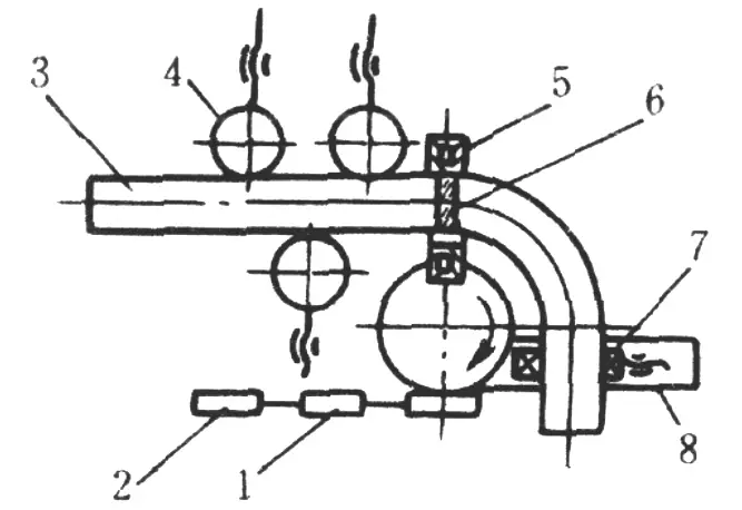
The structure of the fixed manual pipe bender is shown in Figure 1-13.
It is a commonly used manual pipe bender made in-house for construction. This pipe bender is composed of a fixed mold wheel 3, a moving mold wheel 2, and a push frame. The edges of the mold wheels have inwardly recessed semicircular grooves, the diameter of which matches the outer diameter of the bent pipe.
When bending the pipe, select the appropriate mold wheel according to the outer diameter and bending radius of the pipe to be bent, fix the mold wheel on the operating platform with a pin, insert the moving mold wheel on the push frame, and place the pipe to be bent in the groove between the fixed mold wheel and the moving mold wheel. One end is fixed in the pipe holder. Then push the handle, rotate around the fixed mold wheel, until the required angle is bent.

Currently, common electric pipe benders include models such as WA27-60, WB27-108, and WY27-159. The WA27-60 model can bend pipes with an outer diameter of 25-60mm; the WB27-108 model can bend pipes with an outer diameter of 38-108mm; the WY27-159 model can bend pipes with an outer diameter of 51-159mm.

The electric tube bender is driven by a motor through a transmission device, which drives the main shaft and the bending die fixed on the main shaft to rotate for tube bending.
When bending the tube, firstly, place the tube to be bent along the guiding die between the bending die and the clamping die, adjust the guiding die to make the tube at the common tangent position of the bending die and the clamping die, and align the bending point with the cutting point.
Then use the U-shaped tube clamp to clamp the end of the tube on the bending die, then start the motor to start bending the tube, so that the bending die and the clamping die rotate with the tube around the bending die. After reaching the required bending angle, stop the machine, remove the U-shaped tube clamp, release the clamping die, and remove the bent tube.
When using the electric tube bender, the bending die, guiding die, and clamping die used must match the outer diameter of the bent tube to avoid the quality of the bent tube not meeting the requirements after bending.
When the outer diameter of the bent tube is greater than 60mm, a bending mandrel must be placed inside the tube. The outer diameter of the mandrel is 1-1.5mm smaller than the inner diameter of the tube and is placed slightly in front of the bending point of the tube; the intersection of the conical part of the mandrel and the cylindrical part should be placed on the bending surface of the tube. As shown in Figure 1-15.
If the mandrel protrudes too far forward, the mandrel will crack when bending; if the mandrel protrudes too far back, the bent tube will have too large a roundness. The correct position of the mandrel can be obtained by the test method. Whenever using a mandrel to bend a tube, all debris should be cleaned out of the tube cavity before bending, and if conditions permit, a small amount of machine oil can be applied to the inner wall of the tube to reduce friction between the mandrel and the tube wall.

The hydraulic pipe bending machine mainly consists of a top die and a pipe support. The function of the top die is the same as the bending die of the electric pipe bending machine. The function and shape of the pipe support are the same as the clamping mold on the electric pipe bending machine. Figure 1-16 shows the appearance of the hydraulic pipe bending machine.
When using this pipe bender for hydraulic annealing, first move the top die back to behind the pipe support, then place the pipe in the arc groove between the top die and the pipe support, and align the center of the pipe’s bend with the midpoint of the top die. Then start the machine and bend the pipe to the required angle. After bending, reverse the machine to move the top die back to its original position, remove the annealed bend, and check the angle. If the angle is insufficient, you can continue to bend.

This type of pipe bender has simple, light, and powerful dies that can bend large diameter pipes. However, when bending large diameter pipes, the cross-section of the bent pipe is often severely deformed. Therefore, it is generally used for bending pipes with an outer diameter not exceeding 44.5mm.
When using this type of pipe bender to anneal pipes, the bending angle should not exceed 90° each time. During operation, it is also necessary to adjust the distance between the two pipe supports to just allow the top die to pass through. If it is too small, the top die will push on the pipe support, damaging the pipe bender; if it is too large, the pipe section between the pipe supports will bend and deform during bending, affecting the pipe bending quality.
The medium frequency pipe bender uses medium frequency electrical energy to induce local ring heating of the pipe, while mechanically dragging the pipe to rotate, spraying water to cool, making the pipe bending work continuously coordinated.
Using this pipe bender, a 325×10mm elbow can be bent, the bending radius is 1.5 times the nominal diameter of the pipe, which is nearly 10 times more efficient than heating and annealing the pipe with coke carbon.
Compared with common cold bending pipe equipment, this pipe bender has the advantages of less land occupation, low cost, no need for expensive molds, and convenient adjustment of bending radius. Its structure is shown in Figure 1-17.
When bending the pipe, first remove the floating rust and dirt on the surface of the pipe to be bent, install the pipe chuck that matches the specifications of the pipe to be bent on the rotating arm, and adjust the centerline of the chuck to the required bending radius position, and then fix it;
Then, adjust the position of the support roller so that the distance from the centerline of the bent pipe to the center of the rotating arm shaft is equal to the bending radius.
Adjust the height of the support roller and bracket to make the centerline of the bent pipe and the center of the chuck in the same plane, and parallel to the plane of the rotating arm; Insert the steel pipe into the heating ring and clamp it in the chuck;
Adjust the heating ring to make its inner side consistent with the gap between the outer surface of the steel pipe. Start the medium frequency unit for heating. When the pipe is heated to 950—1000°C (orange-yellow), immediately start the motor for bending; at the same time, open the cooling water valve to spray water to cool the local parts.
During pipe bending, if the temperature of the pipe is too high, the speed of the rotating arm can be appropriately increased; otherwise, the speed of the rotating arm is slowed down to keep the heating area of the steel pipe at the same temperature.
When bent to the required angle, stop heating, and stop the motor at the same time (but do not stop in the middle of pipe bending), and continue to pour water for cooling, until the bent pipe is cooled to room temperature, remove the bent pipe, and check whether the bending angle and quality meet the requirements.

As the founder of MachineMFG, I have dedicated over a decade of my career to the metalworking industry. My extensive experience has allowed me to become an expert in the fields of sheet metal fabrication, machining, mechanical engineering, and machine tools for metals. I am constantly thinking, reading, and writing about these subjects, constantly striving to stay at the forefront of my field. Let my knowledge and expertise be an asset to your business.